Design And Analysis Of Machining (Hydraulic) Fixture For AVTEC
Transmission Case Component
S.D.V.V.S.B.REDDY
1PG Student
Prasiddha College of
Engineering & Tech
Anathavaram, Amalapuram
[email protected]
P SATISH REDDY
2Associate Professor
Prasiddha College of
Engineering & Tech
Anathavaram, Amalapuram
[email protected]
V SUBRAHMANYAM
3Associate Professor
Srinivasa Institute of
Engineering & Tech.
Amalapuram.
vasuma999 @gmail.com
Abstract— In order to have interchangeable parts in mass production, jigs and fixtures play a vital role in manufacturing process. A fixture is a special tool designed for specific purpose and for specific component for operation. The present work deals with the design of machining fixture for milling and drilling operations for a crank case. The cutting forces involved in the operations are taken into consideration for designing the fixture.
The present fixture designed is hydraulic operated and used for operation like face milling, drilling, Tapping, Rough &Finish Boring of the crank case. Design standards are taken from Makino for designing this machining fixture. In the design process based on the geometry of the component to be machined, the machine, the table layout and corresponding clamping slot positions are then selected.
Since the final component cannot be produced by a single operation it is necessary to plan for various operations to get the final shape. The fixture is then designed by considering all the clamping forces from various cutting operations.
Keywords–jigs, fixture, Design,Ansys, etc
I. INTRODUCTION
Fixtures are devices which are designed to repeatedly and consistently maintain the orientation of a work piece during machining, assembling, welding, inspection etc. They are an essential part of manufacturing. Fixtures are used to locate the work quickly and accurate support it properly and hold it securely, thereby ensuring that all parts. Produced in the fixture will come out alike within the specified limits, in this Way accuracy and interchangeability of the parts are
manufacturing operation. As a general rule it is provided with devices for supporting and clamping the work piece. It is fixed to the machine bed by clamping in such a position that the work in the correct relationship to the machine tool elements.
These are the devices, which accelerate the production particularly with 100% interchangeable parts. The origin of fixtures can be traced back to the Swiss watch and Clock industry from which after proving their usefulness they spread throughout the metal working industry.
Inside of machine shop Jigs and Fixtures are used for the following operations: Boring, Broaching, Drilling, Grinding, Honing, Lapping, Milling, Planning, Profiling, Reaming, Sawing, Shaping, Slotting, Spot facing, Tapping and Turning. Outside of the machine shop, fixtures may be applied to advantage for: Assembly, Brazing, Heat treating, Inspecting, Riveting, Soldering, Testing and welding
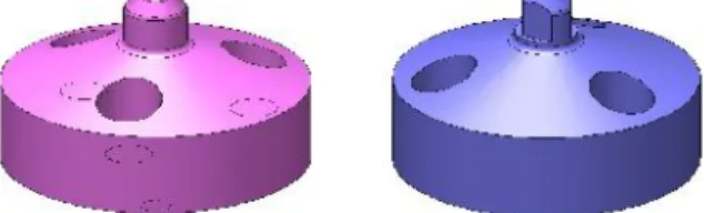
Transmission Case
Fig-1
The above fig shows the transmission case for which a machining fixture is to be designed to perform the different type of operations i.e. boring, milling, taps, drilling etc.
Component details:
Material–Aluminum
Weight of the raw casting =11.22Kg
Weight of the finished component =10.15Kg
Operations to be performed on Crankcase are (1) Drilling (2) Reaming (3) Tapping (4) End milling (5) Boring
Fixture details:
Type: Hydraulic
Clamping force: 19.55 KN
Component Machining Details
Fig-2
REQUIRED DATA TO DESIGN THE FIXTURE:
S.NO REQUIRED DATA WHY REQUIRED?
1 Component Details:
Drawing (pre-machined & machined) Operations to be performed. Input condition of the component. Casting
Forging Pre-Machined 3-D model of component. Material.
Co-efficient of friction of material. Strength
Poisons ratio Hardness
To decide
Locating surface Clamping surface Resting surface
To calculate Clamping force.
To do FEM analysis.
2 Process Related Details Type of operation Spindle speed Feed
Depth of cut (doc) Width of cut
To calculate Cutting force
3 Cutting tools Details Tool dimension Tool geometry Tool material
To calculate cutting force To check interference With any fixture parts. To check reach of the tool to machining area of the component.
4 Machining Details Max. movement of spindle Machine bed details Indexer detail
To check interference with any fixture parts
To mount the fixture on machine
5 Demand Capacity To decide type of clamping manual or power clamping.
6 Process capability details To decide accuracy of fixture
Rigidity of the fixture
7 Cost Investment To decide type of clamping manual or power clamping.
8 Different variety of the component to run on the same machine.
To consider set-up change over
Fig-3
Fixture Elements:
1. Base structure (weldment)
It is made by Mild steel (Alloy steel). It is rigid and can withstand high vibrations. This structure is designed & modeled by depending upon the customer requirement. The main requirement of the customer is to reduce the chip accumulations. Similarly, the weight of the structure is also considered because the machine can bear limited weight (check machine specifications).
The size of the structure is considered depending upon spindle working area, tool changing area and finally total swing area of pallet in the machine. Here the weldment structure is provided with machining allowances for required machining area .And also considered parts fixing holes and hydraulic piping holes on base structure Before going to provide Hydraulic pipe holes we have to be careful about leakage of oils, which will occur in overlapping of oil connections and there should be provided minimum material to withstand the hydraulic oil pressure. Figure 4 shows the base structure of weldment type. Front face will accommodate rest pads and cylindrical and diamond pins and clamp cylinders. The bottom faces rest on the Pallet. Perpendicularity tolerance will be 10 microns. After welding it should be heat treated to relive thermal stress.
Base structure (weldment) Fig-4
2. Rest pad
It is made by En-353 material. Component is rest on this rest pads. Fig 5 shows the rest pad with ASC. Mainly where ever air holes are located air seat check holes are given to the rest plate to check for proper resting of the component. This rest pad is fixed to the base structure by using M6 socket head cap screws. O-rings are placed at the connection of base structure & rest pad for avoiding leakage of air. It works on pneumatics i.e. if there is any leakage of air through it, it sends signals to the machine and the machine stops.
Rest Pad with ASC
Fig-5
The clamp cylinders are double acting and works @ 7Mpa pressure. It gives 5 KN & 4.5KN force respectively at maximum pressure rating i.e. 7Mpa. The Hydraulic connections are given externally to weldment structure and standard hydraulic fittings. Clamp lever is fitted to this hydraulic cylinder. Material used for clamp lever is C45 which is toughened. This allows for the firm holding of the component Swing stroke is 6.5 mm. and locking stroke is 10mm.
Swing clamp assembly (back side) Fig-6
Swing clamp assembly (front side) Fig-7
4. Front side clamp setup
Two hydraulic swing clamps are used for clamping the component in this fixture. Fig 7 shows the front clamp setup for component. The cylinders are double acting and works on 7Mpa pressure. It gives 9.0KN force at maximum pressure rating i.e. 7Mpa. To support these swing clamp cylinders a frame is designed such that both swing clamp cylinders are maintained at same height and also a work support is provided to support the component at the middle to position accurately. The Hydraulic connections are given by internal holes in the frame and standard hydraulic fittings. Clamp lever with swivel pad is fitted to this hydraulic cylinder. The clamp pad is En353 case hardening steels. This allows for the firm holding of the casting surfaces of the Transmission case. Positive stroke should be 5mm as per customer requirement.
Front side clamp setup Fig-8
5.
Rough guideMain purpose of the rough guide is to guide component while loading and unloading of the component, fig. 9 & 10 shows rough guides used for the fixture. In this fixture two types of rough guides were used one is conventional type of rough guide and another one is bottom rough guide which is used to support the bottom side of the component while loading. Distance between the component and rough guide is 2mm. Material used for rough guide is C45
Fig-9
Bottom Rough guide Fig-10
6. Locators
The locators must properly position the work piece and then maintain its location against primary cutting forces throughout the machining cycle. Figure 11 shows the cylindrical pin and diamond pin, taper on top of the locator should be designed for easy loading unloading .As it is a locating element it should have high hardness so the locator is made with single piece of EN353 Case harden & Tempered with 58 To 62 HRC. Threads are kept soft during hardening process.
Cylindrical pin and diamond pin Fig-11
III STUDY OF COLLECTED DATA
Location and orientation
o Should be most accurate feature.
o Should be geometrically related with the features, which need to be machined.
Resting
o Component shall be rested on suitable position.
o Resting element shall be easily replaceable.
Clamping
o Component shall be clamp above the resting face.
o Clamping face should have sufficient wall thickness.
o To clamp casting face, serrations on clamp pad need to be provided.
Permanent butting, a support for the Component needed
CUTTING FORCE CALCULATIONS Cutting force calculation for face milling Input conditions
Milling cutter diameter (Dc) = 63 mm Cutting speed (Vc) = 800 m/min Feed (fz) = 0.12/teeth No. of teeth (Zn) = 5 V, f & Zn values taken from catalogues
Output conditions
Spindle speed (N) = (1000*Vc)/ (∏*D)
For D = 63mm & Vc = 800m/min Spindle speed N = 4042 rpm
Table feed (Vf) = fz * N * Zn mm/min Vf = 2425 mm/min
Cutting time (T) = cutting length (Im) / (feed/t * no.of.teeth * spindle rpm)
For cutting length of 596mm
Cutting time (T) = 596/ (0.12*5*4042) = 0.25 min
Cutting power (Q) = (depth of cut*width of cut*table speed*specific cutting force)/ (60*10^ (6)*0.8)
So, for 60 dia cutter,
Cutting power = (2.5*63*2425*700)/ (60*10^ (6)*0.8) = 5.57Kw
Cutting force = (cutting power*6120)/ (cutting speed*100) = 426 N
Torque = (power*975)/ (100*spindle speed) = 13.44 Nm
Cutting force calculation for hole Ø14 Drilling
Input condition :
Drill diameter (Dc) = 14 mm Feed (fz) = 0.18/teeth Cutting speed (Vc) = 180 m/min No. of teeth (Zn) = 2
Material factor (k) = 0.55 (From CMTI Hand Book) V, f & Zn values taken from catalogues
Output condition
Spindle speed (N) = (1000*Vc)/ (∏*D)
For D= 14mm & V =180 m/min Spindle speed N = 4100 rpm
= 3873.91N
Power = 1.25 * Dc2* K *N *(0.056+1.5 * f) / 105KW = 3.96 KW
Torque (F (tq)) = 0.634*f^ (0.8)* D1.8
= 12.6 N-m
Cutting force calculation for Tapping (M20) Input condition
Tap diameter (D) = M20
Feed (fz) = 1.50mm/teeth Cutting speed (Vc) = 35 m/min Pitch = 1.25mm No. of Teeth (Zn) = 1
Material factor (k) = 0.55 (from CMTI hand book) V and f values taken from catalogues
Output condition
Spindle speed (N) = (1000*V)/(∏*D)
For D=20mm & V =35m/min Spindle speed N = 560 rpm
Cutting time (T) = cutting length/(feed/t* spindle rpm)
For cutting length of 46mm Cutting time (T) = 0.26 min For 75%thread engagement
Cutting power = (0.326*D*pitch^ (2)*N*k)/ 104 = 0.313Kw
Torque = (power*975)/( spindle speed) = 0.546Nm
Cutting force calculation for Boring Input condition
Casting hole diameter (d) = 51.5 mm Boring bar diameter (D) = 52 mm Cutting speed (Vc) = 160 (m/min) Feed (fz) = 0.10/t No. of teeth (Zn) = 2 V, f & Zn values taken from catalogues
Output condition
Spindle speed (N) = (1000*Vc)/(∏*D)
For D=52 mm & V = 160 m/min Spindle speed N = 990 rpm
Table Feed (f) = fz * N * Zn mm/min = 200 mm/min
Cutting time(T) = cutting length/ (feed/t*no.of.teeth*spindle rpm)
For cutting length of 90mm
Cutting time (T) = 0.19 min
Cutting power = ((∏*D^ (2)/4)– (∏*d2/4) * table speed) /
(1000*60*9.8)*(sp.cutting force) *10^ (6) / 0.8*1000)
Cutting power = 1.2 Kw
Torque = (power)/ (0.105*spindle speed) = 11.6 Nm
Cutting force = (torque*2000) / (tool diameter) = 446.5 N
Selection of clamping cylinder
In case of Crank case assy the maximum cutting force developed is 3081.91N (Drilling) which uses Ø21.1 mm drilling cutter for cutting depth/length of 119mm
Clamping Force = 3 times of Cutting force = 3x3873.91N = 11621.7 N Clamping Force = 11.62 KN
So, the clamping force should be more than 12KN while selecting the clamping cylinders.
Clamping cylinders used are model CTU06 Make: PASCAL
Clamping Force is calculated by F=P/ (1.20+0.0032*L) KN Where P=Pressure used (7Mpa)
L=Dist. b/w centre of the clamping cylinder to the clamping point
L=58mm
F=7/ (1.20+0.0032*58) F=5.05kN
Total Clamping cylinders planned are 4
So, the total clamping force is 4*5.05=20.20KN
As the required clamping force is more, it is recommended to go for Hydraulic Cylinders
The hydraulic elements are selected from standard catalogues available as per the requirement and applications. The straight stud fittings are used for connecting oil ports
with the cylinders and G1/8” plugs are used to plug the
holes.
This cylinder is used to actuate the swing clamp. This is double acting cylinder thus two lines is required for suction and discharge of oil. The piston of this cylinder is linked to the clamp lever to transmit the cylinder force to the component for holding the component securely while operation. Thus the basis for selection of this cylinder is the force required to counter the thrust force during cutting.
Fig-12
IV
ANALYSIS OF FIXTURE BODY AND
RESULTS
Analysis of the fixture body is done to check whether the fixture is withstanding the maximum cutting force during machining. Stress analysis and displacement distribution analysis is performed. Based on these results the width of the structure is decided.
Selection of Fixture Body
The customer is using horizontal machining center for the component machining. My concept is to keep the component vertically to the machine bed. For this purpose, I selected Weldment structure. This structure should withstand the cutting forces applied.
This weldment dimensions should fall under the work envelope of specific machine and it could accommodate the component and fixture elements, (i.e. Clamps, rest pads, mounting blocks etc.)
Therefore the dimensions of base plate (Fixture Base), the thickness of base plate will be decided by the analysis done using ANSYS (WORK BENCH) as below.
Base structure Displacement Analysis
A. Meshing Properties
B. Mesh Type : Solid mesh
C. Smooth Surface : On
D. Jacobian Check : 4 Points
E. Element Size : 10 mm
F. Tolerance : 0.67925 mm
G. Quality : High
H. Number of elements : 40028
Base structure displacement Plot Fig-13
The above fig shows the displacement of the structure when the maximum cutting force is developed.
Strain displacement
S.No Type Min max
1 Strain
displacement 0 mm 0.023mm
Base structure stress analysis
J. Material Properties
Material : M.S (low alloy steel) Mass : 304.184 kg
Volume : 0.038749 m3
K. Elastic modulus : 2.1x10⁵N/mm2
L. Poisson's ratio : 0.3
M. Mass density : 7850 kg/m3
N. Tensile strength : 1724 N/mm2
Base structure Stress analysis Fig-14
The above fig shows the stress analysis of the structure when the maximum cutting force is developed.
Vonmisses stress
S. No Type Minimum Maximum
1 Vonmisses
stress 16.57 N/m
2 5.99x10 6
N/m2
Analysis results Stress Result
By this analysis the stress induced is 5.99MPa at maximum force of drilling (3.873KN). The maximum shear stress for mild steel is 250 MPa. So, as the shear stress developed during machining for a maximum cutting force is within the permissible limits .Thus we can conclude that the structure designed is safe
Displacement Result
By this analysis the deflection is 23 microns at maximum force of drilling (3.873KN). F.O.S for the structure is 42. Since the maximum shear stress for mild steel is 250 Mpa and the F.O.S is more than 1 it can be concluded that the structure designed is safe and it can with stand the max. Cutting forces developed during machining.
V CONCLUSION
This fixture is designed for “AVTEC TRANSMISSION CASE”. The following are the results obtained while
designing and from tryout of the fixture.
The stress developed during the maximum cutting force during machining is within the limits i.e., 5.99 Mpa.
Displacement developed during the maximum cutting force is within the limits i.e., 23 Microns.
As the factor of safety obtained is 42 which is more than 1, hence the design is safe.
If the fixture is a mechanical type which takes loading time, the main advantage of this hydraulic fixture is to reduce the loading time
Component has achieved the required accuracy.
Future
scope:-The present work is part of the process, which contains six setups for the set of operations described. It is possible
to bring maximum of the operations in four setups so that the quality characteristics can be more stringently achieved.
VI REFERENCES
[1] K. Henriksen, “Locating Principles”, Jigs and
Fixture Design Manual, Industrial press Inc, New York.
[2] Zhizhong Yan “Fixture Design and Manufacturing”in March 18, 2004.
[3] Machine Tool Design Hand Book, by Central Machine Tool Institute (CMTI), Bangalore. [4] “Jig and Fixture Design” by Edward G.
Hoffman, Fifth Edition, Thomson Delmar Learning.
[5] Tool Engineering Parameter Book, CITD Hyderabad.
[6] Kosmek Catalogue for Hydraulic elements. [7] “Production Technology” by HMT, TMH
Publications.
[8] Frank W. Wilson and John M Holt, “Hand Book of Fixture Design” McGraw-Hill book Company, New Delhi.
[9] H.W. Hardy, “Clamping Devices, Simple Finger Cams”, Jigs and fixture details and units, the
machinery publishing co. Ltd.
[10] Amitabhaghosh and shock Kumar mallik,
“Machining Process”, Affiliated East-west press Pvt. Ltd. New-Delhi.