Modular I/O-System
PROFIBUS DP/V1
Programmable Field Bus
Controller 750-833
Manual
Technical description,
installation and
WAGO-I/O-SYSTEM 750 Bus System
Copyright © 2008 by WAGO Kontakttechnik GmbH & Co. KG. All rights reserved.
WAGO Kontakttechnik GmbH & Co. KG
Hansastraße 27 D-32423 Minden Phone: +49 (0) 571/8 87 – 0 Fax: +49 (0) 571/8 87 – 1 69 E-Mail: [email protected] Web: http://www.wago.com Technical Support Phone: +49 (0) 571/8 87 – 5 55 Fax: +49 (0) 571/8 87 – 85 55 E-Mail: [email protected]
Every conceivable measure has been taken to ensure the correctness and completeness of this documentation. However, as errors can never be fully excluded we would appreciate any information or ideas at any time. E-Mail: [email protected]
We wish to point out that the software and hardware terms as well as the trademarks of companies used and/or mentioned in the present manual are generally trademark or patent protected.
Table of Contents
1 Important Notes ... 9
1.1 Legal Principles... 9
1.1.1 Copyright ... 9
1.1.2 Personnel Qualification ... 9
1.1.3 Conforming Use of Series 750 ... 10
1.1.4 Technical Condition of the Devices ... 10
1.2 Standards and Regulations for Operating the 750 Series... 11
1.3 Symbols ... 12 1.4 Safety Information... 13 1.5 Font Conventions ... 14 1.6 Number Notation... 14 1.7 Scope ... 15 1.8 Abbreviation... 15 2 The WAGO-I/O-SYSTEM 750 ... 16 2.1 System Description... 16 2.2 Technical Data... 17 2.3 Manufacturing Number ... 23 2.4 Component Update... 24
2.5 Storage, Assembly and Transport ... 24
2.6 Mechanical Setup ... 25
2.6.1 Installation Position ... 25
2.6.2 Total Expansion... 25
2.6.3 Assembly onto Carrier Rail ... 26
2.6.3.1 Carrier Rail Properties ... 26
2.6.3.2 WAGO DIN Rail ... 27
2.6.4 Spacing ... 27
2.6.5 Plugging and Removal of the Components ... 28
2.6.6 Assembly Sequence ... 29
2.6.7 Internal Bus/Data Contacts... 30
2.6.8 Power Contacts ... 31 2.6.9 Wire Connection... 32 2.7 Power Supply ... 33 2.7.1 Isolation ... 33 2.7.2 System Supply ... 34 2.7.2.1 Connection ... 34 2.7.2.2 Alignment ... 35 2.7.3 Field Supply... 37 2.7.3.1 Connection ... 37 2.7.3.2 Fusing... 38
WAGO-I/O-SYSTEM 750 Bus System 2.8.1.2 Insulated Assembly... 44 2.8.2 Grounding Function... 45 2.8.3 Grounding Protection ... 46 2.9 Shielding (Screening) ... 47 2.9.1 General... 47 2.9.2 Bus Conductors... 47 2.9.3 Signal Conductors... 47
2.9.4 WAGO Shield (Screen) Connecting System... 48
2.10 Assembly Guidelines/Standards... 48
3 Programmable Field Bus Controller 750-833 ... 49
3.1 Description ... 49
3.2 Hardware ... 51
3.2.1 View... 51
3.2.2 Device Supply... 52
3.2.3 Field Bus Connection ... 53
3.2.4 Display Elements ... 54
3.2.5 Station Address... 55
3.2.6 Configuration and Programming Interface... 56
3.2.7 Operating Mode Switch... 57
3.3 Operating System ... 58
3.3.1 Run-Up ... 58
3.3.2 PFC Cycle... 59
3.4 Process Image... 61
3.4.1 Local Process Image ... 61
3.4.2 Allocation of the Input and Output Data ... 62
3.4.3 Process Data Structure for PROFIBUS-DP... 64
3.4.4 Data Exchange ... 64
3.4.5 Memory Areas ... 64
3.4.6 Addressing ... 67
3.4.6.1 I/O Module Data ... 67
3.4.6.2 Field Bus Variables... 68
3.4.6.3 Flags... 68
3.4.6.4 Calculate Addresses ... 68
3.4.6.5 Example for Absolute Addresses... 69
3.5 Programming of the PFC with WAGO-I/O-PRO... 70
3.5.1 PROFIBUS Library for WAGO-I/O-PRO... 70
3.5.2 IEC 61131-3 Program Transfer ... 71
3.5.2.1 Transmission via the Serial Interface... 71
3.5.2.2 Transmission via the Field Bus... 73
3.5.2.2.1 MSAC2 Interface ... 74
3.6 Configuration... 76
3.6.1 Configuration of the I/O Modules ... 76
3.6.2 Configuration of the Field Bus Variables... 77
3.6.3 GSD Files... 78
3.6.4 Identification Bytes... 79
3.6.4.1 Bus Controller Modules... 82
3.6.4.2 I/O Modules ... 82
3.7 Parameterization of the Controllers... 85
3.8 Configuration and Parameterization of the Modules ... 88
3.8.1 Process Data Channel of the Bus Controller ... 88
3.8.2 Parameterization of I/O Modules ... 89
3.9 Diagnostics ... 90
3.9.1 Stations Status 1 to 3 ... 91
3.9.2 PROFIBUS DP Master Address... 91
3.9.3 Manufacturer Identification... 91
3.9.4 Identification based Diagnostics... 91
3.9.5 Device Status ... 92
3.9.5.1 Internal Status Messages and Arguments ... 93
3.9.5.2 Internal Bus Status Messages and Arguments... 93
3.9.5.3 PROFIBUS DP Status Messages and Arguments ... 94
3.9.5.4 PFC-RTS Status Messages and Arguments... 94
3.9.6 Channel Based Diagnostics ... 95
3.9.6.1 Fault Types of I/O Modules with Diagnostics Capability ... 97
3.9.6.2 I/O Modules Fault Cases... 98
3.9.7 Parameterization Status PROFIsafe... 100
3.9.7.1 PROFIsafe Parameterization Fault ... 100
3.10 Acyclic Communication According to DP/V1... 101
3.10.1 Data Areas ... 103
3.10.1.1 Field Bus Coupler, Slots 0 and 1 ... 104
3.10.2 Complex I/O Modules, Slots 1 ... 63 ... 105
3.10.2.1 Binary I/O Modules, Slots 1 ... 63 ... 105
3.11 LED Signaling... 109
3.11.1 Blink Code... 109
3.11.2 Field Bus Status ... 110
3.11.3 Fault Message via Blink Code of the BUS LED ... 111
3.11.4 Node Status... 112
3.11.5 Fault Message via Blink Code of the I/O LED ... 114
3.11.6 Supply Voltage Status ... 118
3.12 Fault Behavior ... 119
3.12.1 Field Bus Failure ... 119
3.12.2 Internal Bus Fault ... 119
3.13 Technical Data... 120
4 Field Bus Communication ... 122
4.1 PROFIBUS... 122
4.1.1 Description... 122
4.1.2 Wiring... 123
5 I/O Modules ... 126
WAGO-I/O-SYSTEM 750 Bus System
5.2.1 2 DI I/O Modules... 135
5.2.2 2 DI I/O Modules with Diagnostics... 135
5.2.3 4 DI I/O Modules... 136
5.2.4 8 DI I/O Modules... 136
5.2.5 16 DI I/O Modules... 136
5.2.6 2 DO I/O Modules ... 136
5.2.7 2 DO I/O Modules with Diagnostics ... 137
5.2.8 4 DO I/O Modules ... 137
5.2.9 4 DO I/O Module with Diagnostics... 137
5.2.10 8 DO I/O Modules ... 138
5.2.11 8 DO I/O Module with Diagnostics... 138
5.2.12 16 DO I/O Modules ... 138
5.2.13 Power Supply Modules... 138
5.2.14 2 AI I/O Modules... 139 5.2.15 4 AI I/O Modules... 140 5.2.16 2 AO I/O Modules ... 141 5.2.17 4 AO I/O Modules ... 142 5.2.18 Counter Modules ... 143 5.2.19 PWM Module ... 144 5.2.20 Stepper Controller... 144
5.2.21 SSI Encoder Interface ... 145
5.2.22 Incremental Encoder Interfaces ... 146
5.2.23 Digital Impulse Interface ... 146
5.2.24 Serial Interface... 147
5.2.25 Data Exchange Module... 148
5.2.26 DALI/DSI Master ... 149
5.2.27 AS Interface Master... 149
5.2.28 PROFIsafe I/O Modules ... 150
5.3 PROFIBUS Identification Bytes of I/O Modules... 151
5.3.1 Binary Input Modules... 151
5.3.2 Binary Output Modules ... 152
5.3.3 Supply Modules ... 152
5.3.4 Analog Input Modules ... 153
5.3.5 Analog Output Modules ... 153
5.3.6 Special Modules ... 154
5.3.7 Field Bus Variables ... 155
5.3.7.1 PFC Input Variables in the Field Bus Output Process Image... 155
5.3.7.2 PFC Output Variables in the Field Bus Input Process Image... 158
5.4 Configuration and Parameterization of the I/O Modules ... 161
5.4.1 Digital I/O Modules... 161
5.4.1.1 2 DI I/O Modules ... 162
5.4.1.2 2 DI I/O Modules with 1 Bit Diagnostics per Channel... 163
5.4.1.3 4 DI I/O Modules ... 165
5.4.1.4 8 DI I/O Modules ... 166
5.4.1.5 16 DI I/O Modules ... 167
5.4.1.6 2 DO I/O Modules ... 168
5.4.1.7 2 (1) DO I/O Modules with 1 Bit Diagnostics per Channel ... 169
5.4.1.8 2 DO I/O Module with 2 Bit Diagnostics per Channel... 171
5.4.1.10 4 DO I/O Modules with 1 Bit Diagnostics per Channel ... 174
5.4.1.11 8 DO I/O Modules ... 176
5.4.1.12 8 DO I/O Modules with 1 Bit Diagnostics per Channel ... 178
5.4.1.13 16 DO I/O Module ... 180
5.4.1.14 2 DI/DO I/O Modules with 1 Bit Diagnostics per Channel... 181
5.4.1.15 Power Supply Modules with Diagnostics... 183
5.4.2 Analog I/O Modules ... 185
5.4.2.1 2 AI I/O Modules ... 185
5.4.2.2 4 AI I/O Modules ... 187
5.4.2.3 2 AO I/O Modules ... 188
5.4.2.4 4 AO I/O Modules ... 190
5.4.3 Digital Special Modules ... 192
5.4.3.1 Counter Modules... 192
5.4.3.2 PWM Module... 193
5.4.3.3 Stepper Controller... 194
5.4.4 Distance and Angle Measurement Modules... 195
5.4.4.1 SSI Encoder Interface ... 195
5.4.4.2 Incremental Encoder Interface... 196
5.4.4.3 Digital Impulse Interface ... 197
5.4.5 Serial Interfaces ... 198
5.4.6 Data Exchange Module ... 199
5.4.7 ENOCEAN Receiver Module... 200
5.4.8 DALI/DSI Master ... 201
5.4.9 AS Interface Master... 202
5.4.10 PROFIsafe Modules ... 204
5.5 Acyclic Communication According to DP/V1... 206
5.5.1 2 DI I/O Modules... 206
5.5.2 2 DI I/O Modules with 1 Bit Diagnostics per Channel ... 206
5.5.3 4 DI I/O Modules... 206
5.5.4 8 DI I/O Modules... 207
5.5.5 16 DI I/O Modules... 207
5.5.6 2 DO I/O Modules ... 208
5.5.7 2 DO I/O Modules with 1 or 2 Bit Diagnostics per Channel ... 208
5.5.8 4 DO I/O Modules ... 208
5.5.9 4 DO I/O Modules with 1 Bit Diagnostics per Channel... 209
5.5.10 8 DO I/O Modules ... 210
5.5.11 8 DO I/O Modules with 1 Bit Diagnostics per Channel... 211
5.5.12 16 DO I/O Modules ... 212
5.5.13 2 DI/DO I/O Modules with 1 Bit Diagnostics per Channel ... 213
5.5.14 Supply Module with Diagnostics ... 213
5.5.15 2 AI I/O Modules... 214
5.5.16 4 AI I/O Modules... 215
WAGO-I/O-SYSTEM 750 Bus System
5.5.24 Serial Interfaces and Data Exchange Module... 223
5.5.25 DALI/DSI Master ... 224
5.5.26 AS Interface Master... 224
5.5.27 PROFIsafe I/O Modules ... 225
6 Use in Hazardous Environments ... 226
6.1 Foreword ... 226
6.2 Protective Measures ... 226
6.3 Classification Meeting CENELEC and IEC ... 226
6.3.1 Divisions ... 226
6.3.2 Explosion Protection Group ... 228
6.3.3 Unit Categories ... 229
6.3.4 Temperature Classes... 230
6.3.5 Types of Ignition Protection ... 231
6.4 Classifications Meeting the NEC 500 ... 232
6.4.1 Divisions ... 232
6.4.2 Explosion Protection Groups... 232
6.4.3 Temperature Classes... 233 6.5 Identification ... 234 6.5.1 For Europe ... 234 6.5.2 For America ... 235 6.6 Installation Regulations... 236 7 List of Literature ... 238 8 Index ... 239
1 Important Notes
This section provides only a summary of the most important safety
requirements and notes which will be mentioned in the individual sections. To protect your health and prevent damage to the devices, it is essential to read and carefully follow the safety guidelines.
1.1 Legal Principles
1.1.1 Copyright
This manual including all figures and illustrations contained therein is subject to copyright. Any use of this manual which infringes the copyright provisions stipulated herein, is not permitted. Reproduction, translation and electronic and phototechnical archiving and amendments require the written consent of WAGO Kontakttechnik GmbH & Co. KG, Minden. Non-observance will entail the right of claims for damages.
WAGO Kontakttechnik GmbH & Co. KG reserves the right of changes serving technical progress.
All rights developing from the issue of a patent or the legal protection of utility patents are reserved to WAGO Kontakttechnik GmbH & Co. KG. Third-party products are always indicated without any notes concerning patent rights. Thus, the existence of such rights must not be excluded.
1.1.2 Personnel
Qualification
The use of the product described in this manual requires special qualifications, as shown in the following table:
Activity Electrical specialist Instructed personnel*) Specialists**) having qualifications in PLC programming Assembly X X Commissioning X X Programming X Maintenance X X Troubleshooting X Disassembly X X
Legal Principles
WAGO-I/O-SYSTEM 750
Bus System
All personnel must be familiar with the applicable standards.
WAGO Kontakttechnik GmbH & Co. KG declines any liability resulting from improper action and damage to WAGO products and third party products due to non-observance of the information contained in this manual.
1.1.3 Conforming Use of Series 750
The couplers and controllers of the modular I/O System 750 receive digital and analog signals from the I/O modules and sensors and transmit them to the actuators or higher level control systems. Using the WAGO controllers, the signals can also be (pre-)processed.
The device is designed for IP20 protection class. It is protected against finger touch and solid impurities up to 12.5mm diameter, but not against water penetration. Unless otherwise specified, the device must not be operated in wet and dusty environments.
1.1.4 Technical Condition of the Devices
For each individual application, the components are supplied from the factory with a dedicated hardware and software configuration. Changes in hardware, software and firmware are only admitted within the framework of the
possibilities documented in the manuals. All changes to the hardware or software and the non-conforming use of the components entail the exclusion of liability on the part of WAGO Kontakttechnik GmbH & Co. KG.
Please direct any requirements pertaining to a modified and/or new hardware or software configuration directly to WAGO Kontakttechnik GmbH & Co. KG.
1.2 Standards and Regulations for Operating the 750 Series
Please observe the standards and regulations that are relevant to your installation:
• The data and power lines must be connected and installed in compliance with the standards to avoid failures on your installation and eliminate any danger to personnel.
• For installation, startup, maintenance and repair, please observe the accident prevention regulations of your machine (e.g. BGV A 3, "Electrical Installations and Equipment").
• Emergency stop functions and equipment must not be made ineffective. See relevant standards (e.g. DIN EN 418).
• Your installation must be equipped in accordance to the EMC guidelines so that electromagnetic interferences can be eliminated.
• Operating 750 Series components in home applications without further measures is only permitted if they meet the emission limits (emissions of interference) according to EN 61000-6-3. You will find the relevant information in the section on "WAGO-I/O-SYSTEM 750" ! "System Description" ! "Technical Data".
• Please observe the safety measures against electrostatic discharge according to DIN EN 61340-5-1/-3. When handling the modules, ensure that the environment (persons, workplace and packing) is well grounded.
• The relevant valid and applicable standards and guidelines concerning the installation of switch cabinets are to be observed.
Symbols
WAGO-I/O-SYSTEM 750
Bus System
1.3 Symbols
Danger
Always observe this information to protect persons from injury.
Warning
Always observe this information to prevent damage to the device.
Attention
Marginal conditions that must always be observed to ensure smooth and efficient operation.
ESD (Electrostatic Discharge)
Warning of damage to the components through electrostatic discharge. Observe the precautionary measure for handling components at risk of electrostatic discharge.
Note
Make important notes that are to be complied with so that a trouble-free and efficient device operation can be guaranteed.
Additional Information
1.4 Safety Information
When connecting the device to your installation and during operation, the following safety notes must be observed:
Danger
The WAGO-I/O-SYSTEM 750 and its components are an open system. It must only be assembled in housings, cabinets or in electrical operation rooms. Access is only permitted via a key or tool to authorized qualified personnel.
Danger
All power sources to the device must always be switched off before carrying out any installation, repair or maintenance work.
Warning
Replace defective or damaged device/module (e.g. in the event of deformed contacts), as the functionality of field bus station in question can no longer be ensured on a long-term basis.
Warning
The components are not resistant against materials having seeping and insulating properties. Belonging to this group of materials is: e.g. aerosols, silicones, triglycerides (found in some hand creams). If it cannot be ruled out that these materials appear in the component environment, then the
components must be installed in an enclosure that is resistant against the above mentioned materials. Clean tools and materials are generally required to operate the device/module.
Warning
Soiled contacts must be cleaned using oil-free compressed air or with ethyl alcohol and leather cloths.
Warning
Do not use contact sprays, which could possibly impair the functioning of the contact area.
Warning
Avoid reverse polarity of data and power lines, as this may damage the devices.
Font Conventions
WAGO-I/O-SYSTEM 750
Bus System
1.5 Font Conventions
italic Names of paths and files are marked in italic.
e.g.: C:\Programs\WAGO-IO-CHECK
italic Menu items are marked in bold italic. e.g.: Save
\ A backslash between two names characterizes the
selection of a menu point from a menu. e.g.: File \ New
END Press buttons are marked as bold with small capitals
e.g.: ENTER
< > Keys are marked bold within angle brackets
e.g.: <F5>
Courier The print font for program codes is Courier.
e.g.: END_VAR
1.6 Number Notation
Number code Example Note
Decimal 100 Normal notation
Hexadecimal 0x64 C notation
Binary '100' '0110.0100'
Within inverted commas, Nibble separated with dots
1.7 Scope
This manual describes all components of the field bus independent WAGO I/O SYSTEM 750 with programmable field bus controller.
Item No. Description
750-833 Programmable Field Bus Controller PROFIBUS DP/V1 12 MBd
1.8 Abbreviation
AI Analog Input
Analog Input Module
AO Analog Output
Analog Output Module
CPU In this case the Run Time System for the eradication of the user
program in the PFC
DI Digital Input
Digital Input Module
DO Digital Output
Digital Output Module
FBD Function Block Diagram
HB High Byte I/O Input/Output IL Instruction List ID Identifier LB Low Byte LD Ladder Diagram
PFC Programmalbe Field Bus Controller
PLC Programmable Logic Controller
SFC Sequential Function Chart
ST Structured Text
System Description
WAGO-I/O-SYSTEM 750
Bus System
2 The WAGO-I/O-SYSTEM 750
2.1 System Description
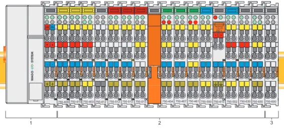
The WAGO-I/O-SYSTEM 750 is a modular, field bus independent I/O system. It is comprised of a field bus coupler/controller (1) and connected field bus modules (2) for any type of signal. Together, these make up the field bus node. The end module (3) completes the node.
Fig. 2-1: Field bus node g0xxx00x
Couplers/controllers for field bus systems such as PROFIBUS, INTERBUS, ETHERNET TCP/IP, CAN (CANopen, DeviceNet, CAL), MODBUS, LON and others are available.
The coupler/controller contains the field bus interface, electronics and a power supply terminal. The field bus interface forms the physical interface to the relevant field bus. The electronics process the data of the bus modules and make it available for the field bus communication. The 24 V system supply and the 24 V field supply are fed in via the integrated power supply terminal. The field bus coupler communicates via the relevant field bus. The
programmable field bus controller (PFC) enables the implementation of additional PLC functions. Programming is done with the WAGO-I/O-PRO in accordance with IEC 61131-3.
Bus modules for diverse digital and analog I/O functions as well as special functions can be connected to the coupler/controller. The communication between the coupler/controller and the bus modules is carried out via an internal bus.
The WAGO-I/O-SYSTEM 750 has a clear port level with LEDs for status indication, insertable mini WSB markers and pullout group marker carriers. The 3-wire technology supplemented by a ground wire connection allows for direct sensor/actuator wiring.
2.2 Technical Data
Mechanic
Material Polycarbonate, Polyamide 6.6
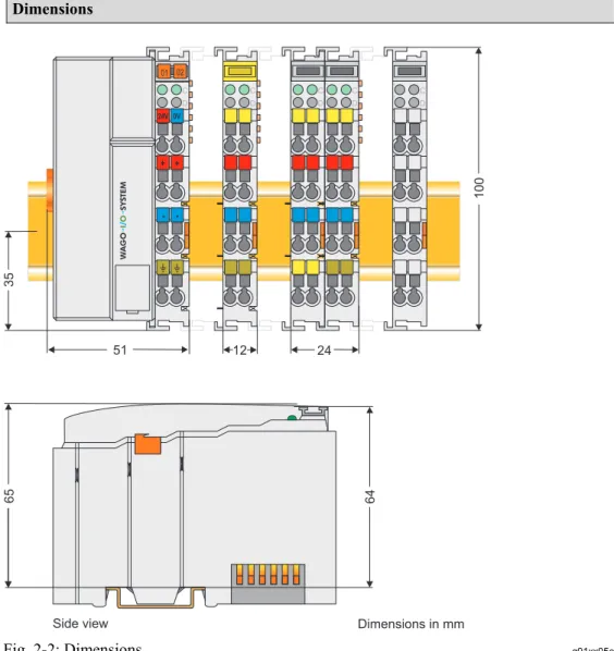
Dimensions W x H* x L
* from upper edge of DIN 35 rail - Coupler/Controller (Standard) - Coupler/Controller (ECO) - Coupler/Controller (FireWire) - I/O module, single
- I/O module, double - I/O module, fourfold
- 51 mm x 65 mm x 100 mm - 50 mm x 65 mm x 100 mm - 62 mm x 65 mm x 100 mm - 12 mm x 64 mm x 100 mm - 24 mm x 64 mm x 100 mm - 48 mm x 64 mm x 100 mm
Installation on DIN 35 with interlock
Modular by double featherkey-dovetail
Mounting position any position
Marking standard marking label type
group marking label 8 x 47 mm Connection
Connection type CAGE CLAMP®
Wire range 0.08 mm² ... 2.5 mm², AWG 28-14
Stripped length 8 … 9 mm,
9 … 10 mm for components with pluggable wiring (753-xxx)
Contacts
Power jumpers contacts blade/spring contact
self-cleaning Current via power contacts max 10 A
Voltage drop at I max < 1 V/64 modules
Data contacts slide contact, hard gold plated
1.5 µm, self-cleaning Climatic environmental conditions
Operating temperature 0 °C ... 55 °C,
-20 °C … +60 °C for components with extended temperature range (750-xxx/025-xxx)
Storage temperature -20 °C ... +85 °C
Relative humidity 5 % … 95 % without condensation
Resistance to harmful substances acc. to IEC 60068-2-42 and IEC 60068-2-43 Maximum pollutant concentration at SO ≤ 25 ppm
Technical Data
WAGO-I/O-SYSTEM 750
Bus System
Safe electrical isolation
Air and creepage distance acc. to IEC 60664-1
Degree of pollution acc. To IEC 61131-2 2 Degree of protection Degree of protection IP 20 Electromagnetic compatibility
Immunity to interference for industrial areas acc. to EN 61000-6-2 (2001)
Test specification Test values Strength
class Evaluation criteria
EN 61000-4-2 ESD 4 kV/8 kV (contact/air) 2/3 B EN 61000-4-3 electromagnetic fields 10 V/m 80 MHz ... 1 GHz 3 A EN 61000-4-4 burst 1 kV/2 kV (data/supply) 2/3 B -/- (line/line) Data: 1 kV (line/earth) 2 B 0.5 kV (line/line) 1 DC supply: 0.5 kV (line/earth) 1 B 1 kV (line/line) 2 EN 61000-4-5 surge AC supply: 2 kV (line/earth) 3 B EN 61000-4-6 RF disturbances 10 V/m 80 % AM (0.15 ... 80 MHz) 3 A
Emission of interference for industrial areas acc. to EN 61000-6-4 (2001)
Test specification Limit values/[QP]*) Frequency range Distance
79 dB (µV) 150 kHz ... 500 kHz EN 55011 (AC supply, conducted) 73 dB (µV) 500 kHz ... 30 MHz 40 dB (µV/m) 30 MHz ... 230 MHz 10 m EN 55011 (radiated) 47 dB (µV/m) 230 MHz ... 1 GHz 10 m
Emission of interference for residential areas acc. to EN 61000-6-3 (2001)
Test specification Limit values/[QP]*) Frequency range Distance 66 ... 56 dB (µV) 150 kHz ... 500 kHz 56 dB (µV) 500 kHz ... 5 MHz EN 55022 (AC supply, conducted) 60 dB (µV) 5 MHz ... 30 MHz 40 ... 30 dB (µA) 150 kHz ... 500 kHz EN 55022 (DC supply/data, conducted) 30 dB (µA) 500 kHz ... 30 MHz 30 dB (µV/m) 30 MHz ... 230 MHz 10 m EN 55022 (radiated) 37 dB (µV/m) 230 MHz ... 1 GHz 10 m
Mechanical strength acc. to IEC 61131-2
Test specification Frequency range Limit value
5 Hz ≤ f < 9 Hz 1.75 mm amplitude (permanent) 3.5 mm amplitude (short term) 9 Hz ≤ f < 150 Hz 0.5 g (permanent)
1 g (short term) IEC 60068-2-6 vibration
Note on vibration test:
a) Frequency change: max. 1 octave/minute b) Vibration direction: 3 axes
15 g
IEC 60068-2-27 shock
Note on shock test: a) Type of shock: half sine b) Shock duration: 11 ms
c) Shock direction: 3x in positive and 3x in negative direction for each of the three mutually perpendicular axes of the test specimen
IEC 60068-2-32 free fall 1 m
(module in original packing) *) QP: Quasi Peak
Note
If the technical data of components differ from the values described here, the technical data shown in the manuals of the respective components shall be valid.
Technical Data
WAGO-I/O-SYSTEM 750
Bus System
For Products of the WAGO-I/O-SYSTEM 750 with ship specific approvals supplementary guidelines are valid:
Electromagnetic compatibility
Immunity to interference acc. to Germanischer Lloyd (2003)
Test specification Test values Strength
class Evaluation criteria
IEC 61000-4-2 ESD 6 kV/8 kV (contact/air) 3/3 B
IEC 61000-4-3
electromagnetic fields 10 V/m 80 MHz ... 2 GHz 3 A
IEC 61000-4-4 burst 1 kV/2 kV (data/supply) 2/3 A
0.5 kV (line/line) 1
IEC 61000-4-5 surge AC/DC
Supply: 1 kV (line/earth) 2 A IEC 61000-4-6 RF disturbances 10 V/m 80 % AM (0.15 ... 80 MHz) 3 A Type test AF disturbances
(harmonic waves)
3 V, 2 W - A
Type test high voltage 755 V DC 1500 V AC
- - Emission of interference acc. to Germanischer Lloyd (2003)
Test specification Limit values Frequency range Distance 96 ... 50 dB (µV) 10 kHz ... 150 kHz
60 ... 50 dB (µV) 150 kHz ... 350 kHz Type test
(EMC1, conducted)
allows for ship bridge control
applications 50 dB (µV) 350 kHz ... 30 MHz
80 ... 52 dB (µV/m) 150 kHz ... 300 kHz 3 m 52 ... 34 dB (µV/m) 300 kHz ... 30 MHz 3 m Type test
(EMC1, radiated)
allows for ship bridge control
applications 54 dB (µV/m) 30 MHz ... 2 GHz 3 m
except: 24 dB (µV/m) 156 MHz ... 165 MHz 3 m
Mechanical strength acc. to Germanischer Lloyd (2003) Test specification Frequency range Limit value
2 Hz ≤ f < 25 Hz ± 1.6 mm amplitude (permanent) 25 Hz ≤ f < 100 Hz 4 g (permanent)
IEC 60068-2-6 vibration (category A – D)
Note on vibration test:
a) Frequency change: max. 1 octave/minute b) Vibration direction: 3 axes
Range of
application Required specification emission of interference Required specification immunity to interference
Industrial areas EN 61000-6-4 (2001) EN 61000-6-2 (2001)
Residential areas EN 61000-6-3 (2001)*) EN 61000-6-1 (2001)
*) The system meets the requirements on emission of interference in residential areas with the field bus coupler/controller for:
ETHERNET LonWorks CANopen DeviceNet MODBUS 750-342/-841/-842/-860 750-319/-819 750-337/-837 750-306/-806 750-312/-314/ -315/ -316 750-812/-814/ -815/ -816
With a special permit, the system can also be implemented with other field bus
couplers/controllers in residential areas (housing, commercial and business areas, small-scale enterprises). The special permit can be obtained from an authority or inspection office. In Germany, the Federal Office for Post and Telecommunications and its branch offices issues the permit.
It is possible to use other field bus couplers/controllers under certain boundary conditions. Please contact WAGO Kontakttechnik GmbH & Co. KG.
Maximum power dissipation of the components
Bus modules 0.8 W / bus terminal (total power dissipation,
system/field)
Field bus coupler/controller 2.0 W / coupler/controller
Warning
The power dissipation of all installed components must not exceed the maximum conductible power of the housing (cabinet).
When dimensioning the housing, care is to be taken that even under high external temperatures, the temperature inside the housing does not exceed the permissible ambient temperature of 55 °C.
Technical Data WAGO-I/O-SYSTEM 750 Bus System Dimensions 51 24V 0V + + - -01 02 C D B A C D B A C D B A C D B A C D B A 100 12 24 64 35 65
Side view Dimensions in mm
Fig. 2-2: Dimensions g01xx05e
Note
The illustration shows a standard coupler. For detailed dimensions, please refer to the technical data of the respective coupler/controller.
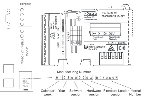
2.3 Manufacturing Number
The manufacturing number indicates the delivery status directly after production.
This number is part of the lateral marking on the component.
In addition, starting from calendar week 43/2000 the manufacturing number is also printed on the cover of the configuration and programming interface of the field bus coupler or controller.
Hansastr. 27 D-32423 Minden ITEM-NO.:750-333 PROFIBUS DP 12 MBd /DPV1 0 V Power Supply Electronic PATENTS PENDING II 3 GD DEMKO 02 ATEX132273 X EEx nA II T4 24V DC A WG 28-14 55°C max ambient LISTED 22ZA AND 22XM 72072 0103000203-B000000 Hansastr. 27 D-32423 Minden ITEM-NO.:750-333 PROFIBUS DP 12 MBd /DPV1 0 V Power Supply Electronic PATENTS PENDING II 3 GD DEMKO 02 ATEX132273 X EEx nA II T4 24V DC A WG 28-14 55°C max ambient LISTED 22ZA AND 22XM 72072 0103000203-B060606 1 0 3 0 0 0 2 0 0 3 DS NO SW HW GL FWL Power Supply Field 24 V + -- B 0 6 0 6 0 6 PROFIBUS WAGO -I/O -SYSTEM 750-333 01030002 03-B 060606 72072 Manufacturing Number Calendar week Year Software version Hardware version Firmware Loader version Internal Number Fig. 2-3: Example: Manufacturing Number of a PROFIBUS field bus coupler 750-333
g01xx15e
The manufacturing number consists of the production week and year, the software version (if available), the hardware version of the component, the firmware loader (if available) and further internal information for
Component Update
WAGO-I/O-SYSTEM 750
Bus System
2.4 Component Update
For the case of an Update of one component, the lateral marking on each component contains a prepared matrix .
This matrix makes columns available for altogether three updates to the entry of the current update data, like production order number (NO; starting from calendar week 13/2004), update date (DS), software version (SW), hardware version (HW) and the firmware loader version (FWL, if available).
Update Matrix
Current Version data for: 1. Update 2. Update 3. Update Production Order
Number NO "calendar week 13/2004 only starting from
Datestamp DS
Software index SW
Hardware index HW
Firmware loader index FWL " only for coupler/
controller
If the update of a component took place, the current version data are registered into the columns of the matrix.
Additionally with the update of a field bus coupler or controller also the cover of the configuration and programming interface of the coupler or controller is printed on with the current manufacturing and production order number. The original manufacturing data on the housing of the component remain thereby.
2.5 Storage, Assembly and Transport
Wherever possible, the components are to be stored in their original packaging. Likewise, the original packaging provides optimal protection during transport.
When assembling or repacking the components, the contacts must not be soiled or damaged. The components must be stored and transported in appropriate containers/packaging. Thereby, the ESD information is to be regarded.
Statically shielded transport bags with metal coatings are to be used for the transport of open components for which soiling with amine, amide and silicone has been ruled out, e.g. 3M 1900E.
2.6 Mechanical Setup
2.6.1 Installation
Position
Along with horizontal and vertical installation, all other installation positions are allowed.
Attention
In the case of vertical assembly, an end stop has to be mounted as an additional safeguard against slipping.
WAGO item 249-116 End stop for DIN 35 rail, 6 mm wide WAGO item 249-117 End stop for DIN 35 rail, 10 mm wide
2.6.2 Total
Expansion
The length of the module assembly (including one end module of 12mm width) that can be connected to the coupler/controller is 780 mm. When assembled, the I/O modules have a maximum length of 768 mm.
Examples:
• 64 I/O modules of 12 mm width can be connected to one coupler/controller.
• 32 I/O modules of 24 mm width can be connected to one coupler/controller.
Exception:
The number of connected I/O modules also depends on which type of
coupler/controller is used. For example, the maximum number of I/O modules that can be connected to a PROFIBUS coupler/controller is 63 without end module. The maximum total expansion of a node is calculated as follows:
Warning
The maximum total length of a node without coupler/controller must not exceed 780 mm. Furthermore, restrictions made on certain types of couplers/controllers must be observed (e.g. for PROFIBUS).
Mechanical Setup
WAGO-I/O-SYSTEM 750
Bus System
2.6.3 Assembly onto Carrier Rail
2.6.3.1 Carrier Rail PropertiesAll system components can be snapped directly onto a carrier rail in accordance with the European standard EN 50022 (DIN 35).
Warning
WAGO Kontakttechnik GmbH & Co. KG supplies standardized carrier rails that are optimal for use with the I/O system. If other carrier rails are used, then a technical inspection and approval of the rail by WAGO
Kontakttechnik GmbH & Co. KG should take place.
Carrier rails have different mechanical and electrical properties. For the optimal system setup on a carrier rail, certain guidelines must be observed:
• The material must be non-corrosive.
• Most components have a contact to the carrier rail to ground electro-magnetic disturbances. In order to avoid corrosion, this tin-plated carrier rail contact must not form a galvanic cell with the material of the carrier rail which generates a differential voltage above 0.5 V (saline solution of 0.3% at 20°C) .
• The carrier rail must optimally support the EMC measures integrated into the system and the shielding of the bus module connections.
• A sufficiently stable carrier rail should be selected and, if necessary, several mounting points (every 20 cm) should be used in order to prevent bending and twisting (torsion).
• The geometry of the carrier rail must not be altered in order to secure the safe hold of the components. In particular, when shortening or mounting the carrier rail, it must not be crushed or bent.
• The base of the I/O components extends into the profile of the carrier rail. For carrier rails with a height of 7.5 mm, mounting points are to be riveted under the node in the carrier rail (slotted head captive screws or blind rivets).
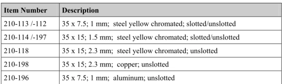
2.6.3.2 WAGO DIN Rail
WAGO carrier rails meet the electrical and mechanical requirements.
Item Number Description
210-113 /-112 35 x 7.5; 1 mm; steel yellow chromated; slotted/unslotted 210-114 /-197 35 x 15; 1.5 mm; steel yellow chromated; slotted/unslotted 210-118 35 x 15; 2.3 mm; steel yellow chromated; unslotted
210-198 35 x 15; 2.3 mm; copper; unslotted
210-196 35 x 7.5; 1 mm; aluminum; unslotted
2.6.4 Spacing
The spacing between adjacent components, cable conduits, casing and frame sides must be maintained for the complete field bus node.
Fig. 2-4: Spacing g01xx13x
The spacing creates room for heat transfer, installation or wiring. The spacing to cable conduits also prevents conducted electromagnetic interferences from influencing the operation.
Mechanical Setup
WAGO-I/O-SYSTEM 750
Bus System
2.6.5 Plugging and Removal of the Components
Warning
Before work is done on the components, the voltage supply must be turned off.
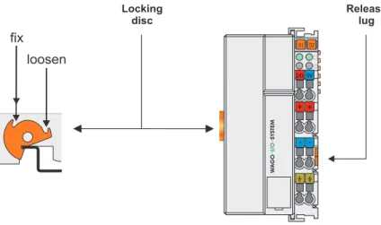
In order to safeguard the coupler/controller from jamming, it should be fixed onto the carrier rail with the locking disc To do so, push on the upper groove of the locking disc using a screwdriver.
To pull out the field bus coupler/controller, release the locking disc by
pressing on the bottom groove with a screwdriver and then pulling the orange colored unlocking lug .
Fig. 2-5: Coupler/Controller and unlocking lug g01xx12e
It is also possible to release an individual I/O module from the unit by pulling an unlocking lug.
Fig. 2-6: removing bus terminal p0xxx01x
Danger
Ensure that an interruption of the PE will not result in a condition which could endanger a person or equipment!
2.6.6 Assembly
Sequence
All system components can be snapped directly on a carrier rail in accordance with the European standard EN 50022 (DIN 35).
The reliable positioning and connection is made using a tongue and groove system. Due to the automatic locking, the individual components are securely seated on the rail after installing.
Starting with the coupler/controller, the bus modules are assembled adjacent to each other according to the project planning. Errors in the planning of the node in terms of the potential groups (connection via the power contacts) are recognized, as the bus modules with power contacts (male contacts) cannot be linked to bus modules with fewer power contacts.
Attention
Always link the bus modules with the coupler/controller, and always plug from above.
Warning
Never plug bus modules from the direction of the end terminal. A ground wire power contact, which is inserted into a terminal without contacts, e.g. a 4-channel digital input module, has a decreased air and creepage distance to the neighboring contact in the example DI4.
Mechanical Setup
WAGO-I/O-SYSTEM 750
Bus System
2.6.7 Internal Bus/Data Contacts
Communication between the coupler/controller and the bus modules as well as the system supply of the bus modules is carried out via the internal bus. It is comprised of 6 data contacts, which are available as self-cleaning gold spring contacts.
Fig. 2-7: Data contacts p0xxx07x
Warning
Do not touch the gold spring contacts on the I/O modules in order to avoid soiling or scratching!
ESD (Electrostatic Discharge)
The modules are equipped with electronic components that may be destroyed by electrostatic discharge. When handling the modules, ensure that the environment (persons, workplace and packing) is well grounded. Avoid touching conductive components, e.g. data contacts.
2.6.8 Power
Contacts
Self-cleaning power contacts , are situated on the side of the components which further conduct the supply voltage for the field side. These contacts come as touchproof spring contacts on the right side of the coupler/controller and the bus module. As fitting counterparts the module has male contacts on the left side.
Danger
The power contacts are sharp-edged. Handle the module carefully to prevent injury.
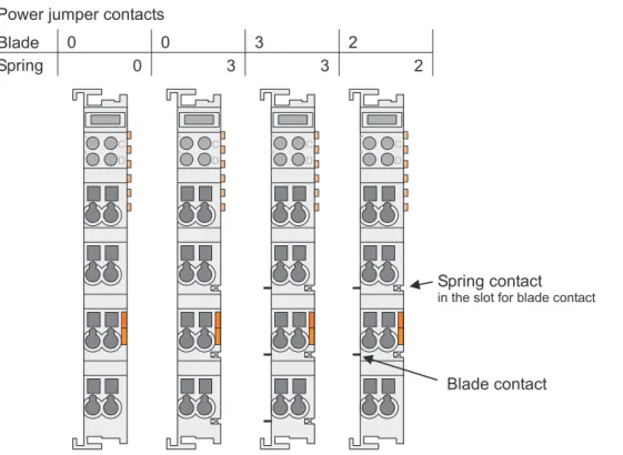
Attention
Please take into consideration that some bus modules have no or only a few power jumper contacts. The design of some modules does not allow them to be physically assembled in rows, as the grooves for the male contacts are closed at the top.
Fig. 2-8: Example for the arrangement of power contacts g0xxx05e
Recommendation
With the WAGO ProServe® Software smartDESIGNER, the structure of a field bus node can be configured. The configuration can be tested via the
Mechanical Setup
WAGO-I/O-SYSTEM 750
Bus System
2.6.9 Wire
Connection
All components have CAGE CLAMP® connections.
The WAGO CAGE CLAMP® connection is appropriate for solid, stranded and finely stranded conductors. Each clamping unit accommodates one conductor.
Fig. 2-9: CAGE CLAMP® Connection g0xxx08x
The operating tool is inserted into the opening above the connection. This opens the CAGE CLAMP®. Subsequently the conductor can be inserted into the opening. After removing the operating tool, the conductor is safely clamped.
More than one conductor per connection is not permissible. If several
conductors have to be made at one connection point, then they should be made away from the connection point using WAGO Terminal Blocks. The terminal blocks may be jumpered together and a single wire brought back to the I/O module connection point.
Attention
If it is unavoidable to jointly connect 2 conductors, then a ferrule must be used to join the wires together.
Ferrule:
Length 8 mm
Nominal cross section max. 1 mm2 for 2 conductors with 0.5 mm2
each
WAGO Product 216-103
2.7 Power Supply
2.7.1 Isolation
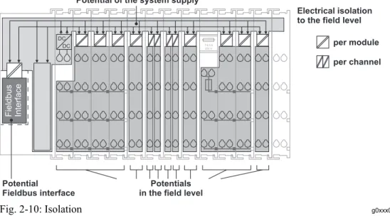
Within the field bus node, there are three electrically isolated potentials.
• Operational voltage for the field bus interface.
• Electronics of the couplers/controllers and the bus modules (internal bus).
• All bus modules have an electrical isolation between the electronics
(internal bus, logic) and the field electronics. Some digital and analog input modules have each channel electrically isolated, please see catalog.
Fig. 2-10: Isolation g0xxx01e
Attention
The ground wire connection must be present in each group. In order that all protective conductor functions are maintained under all circumstances, it is recommended that a ground wire be connected at the beginning and end of a potential group. (ring format, please see chapter 2.8.3). Thus, if a bus module comes loose from a composite during servicing, then the protective conductor connection is still guaranteed for all connected field devices.
When using a joint power supply unit for the 24 V system supply and the 24 V field supply, the electrical isolation between the internal bus and the field level is eliminated for the potential group.
Power Supply
WAGO-I/O-SYSTEM 750
Bus System
2.7.2 System
Supply
2.7.2.1 Connection
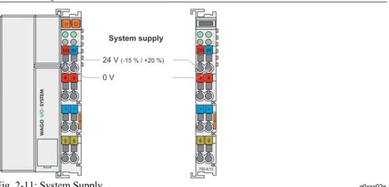
The WAGO-I/O-SYSTEM 750 requires a 24 V direct current system supply (-15 % or +20 %). The power supply is provided via the coupler/controller and, if necessary, in addition via the internal system supply modules (750-613). The voltage supply is reverse voltage protected.
Attention
The use of an incorrect supply voltage or frequency can cause severe damage to the component.
Fig. 2-11: System Supply g0xxx02e
The direct current supplies all internal system components, e.g.
coupler/controller electronics, field bus interface and bus modules via the internal bus (5 V system voltage). The 5 V system voltage is electrically connected to the 24 V system supply.
Attention
Resetting the system by switching on and off the system supply, must take place simultaneously for all supply modules (coupler/controller and 750-613).
2.7.2.2 Alignment
Recommendation
A stable network supply cannot be taken for granted always and everywhere. Therefore, regulated power supply units should be used in order to guarantee the quality of the supply voltage.
The supply capacity of the coupler/controller or the internal system supply module (750-613) can be taken from the technical data of the components.
Internal current consumption*) Current consumption via system voltage: 5 V for electronics of the bus modules and coupler/controller
Residual current for bus
terminals*) Available current for the bus modules. Provided by the bus power supply unit. See coupler/controller and internal system supply module (750-613)
*) cf. catalogue W4 Volume 3, manuals or internet
Example Coupler 750-301:
internal current consumption:350 mA at 5 V residual current for
bus modules : 1650 mA at 5 V
sum I(5V)total : 2000 mA at 5 V
The internal current consumption is indicated in the technical data for each bus terminal. In order to determine the overall requirement, add together the values of all bus modules in the node.
Attention
If the sum of the internal current consumption exceeds the residual current for bus modules, then an internal system supply module (750-613) must be placed before the module where the permissible residual current was exceeded.
Power Supply
WAGO-I/O-SYSTEM 750
Bus System
Example: A node with a PROFIBUS Coupler 750-333 consists of 20 relay modules (750-517) and 10 digital input modules (750-405). Current consumption:
20* 90 mA = 1800 mA
10* 2 mA = 20 mA
Sum 1820 mA
The coupler can provide 1650 mA for the bus modules. Consequently, an internal system supply module (750-613), e.g. in the middle of the node, should be added.
Recommendation
With the WAGO ProServe® Software smartDESIGNER, the assembly of a field bus node can be configured. The configuration can be tested via the integrated accuracy check.
The maximum input current of the 24 V system supply is 500 mA. The exact electrical consumption (I(24 V)) can be determined with the following formulas:
Coupler/Controller
I(5 V)total = Sum of all the internal current consumption of the connected
bus modules
+ internal current consumption coupler/controller 750-613
I(5 V)total = Sum of all the internal current consumption of the connected
bus modules
Input current I(24 V) = 5 V / 24 V * I(5 V)total / η η = 0.87 (at nominal load)
Attention
If the electrical consumption of the power supply point for the 24 V-system supply exceeds 500 mA, then the cause may be an improperly aligned node or a defect.
During the test, all outputs, in particular those of the relay modules, must be active.
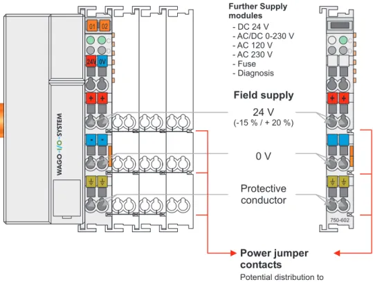
2.7.3 Field
Supply
2.7.3.1 ConnectionSensors and actuators can be directly connected to the relevant channel of the bus module in 1/4 conductor connection technology. The bus module supplies power to the sensors and actuators. The input and output drivers of some bus modules require the field side supply voltage.
The coupler/controller provides field side power (DC 24V). In this case it is a passive power supply without protection equipment.
Power supply modules are available for other potentials, e. g. AC 230 V. Likewise, with the aid of the power supply modules, various potentials can be set up. The connections are linked in pairs with a power contact.
Fig. 2-13: Field Supply (Sensor/Actuator) g0xxx03e
The supply voltage for the field side is automatically passed to the next module via the power jumper contacts when assembling the bus modules . The current load of the power contacts must not exceed 10 A on a continual basis. The current load capacity between two connection terminals is identical to the load capacity of the connection wires.
Power Supply
WAGO-I/O-SYSTEM 750
Bus System
Attention
Some bus modules have no or very few power contacts (depending on the I/O function). Due to this, the passing through of the relevant potential is
disrupted. If a field supply is required for subsequent bus modules, then a power supply module must be used.
Note the data sheets of the bus modules.
In the case of a node setup with different potentials, e.g. the alteration from DC 24 V to AC 230V, a spacer module should be used. The optical
separation of the potentials acts as a warning to heed caution in the case of wiring and maintenance works. Thus, the results of wiring errors can be prevented.
2.7.3.2 Fusing
Internal fusing of the field supply is possible for various field voltages via an appropriate power supply module.
750-601 24 V DC, Supply/Fuse
750-609 230 V AC, Supply/Fuse
750-615 120 V AC, Supply/Fuse
750-610 24 V DC, Supply/Fuse/Diagnosis
750-611 230 V AC, Supply/Fuse/Diagnosis
Warning
In the case of power supply modules with fuse holders, only fuses with a maximum dissipation of 1.6 W (IEC 127) must be used.
For UL approved systems only use UL approved fuses.
In order to insert or change a fuse, or to switch off the voltage in succeeding bus modules, the fuse holder may be pulled out. In order to do this, use a screwdriver for example, to reach into one of the slits (one on both sides) and pull out the holder.
Fig. 2-15: Removing the fuse carrier p0xxx05x
Lifting the cover to the side opens the fuse carrier.
Fig. 2-16: Opening the fuse carrier p0xxx03x
Fig. 2-17: Change fuse p0xxx04x
After changing the fuse, the fuse carrier is pushed back into its original position.
Power Supply
WAGO-I/O-SYSTEM 750
Bus System
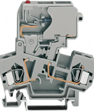
Alternatively, fusing can be done externally. The fuse modules of the WAGO series 281 and 282 are suitable for this purpose.
Fig. 2-18: Fuse modules for automotive fuses, series 282 pf66800x
Fig. 2-19: Fuse modules with pivotable fuse carrier, series 281 pe61100x
2.7.4 Supplementary Power Supply Regulations
The WAGO-I/O-SYSTEM 750 can also be used in shipbuilding or offshore and onshore areas of work (e. g. working platforms, loading plants). This is demonstrated by complying with the standards of influential classification companies such as Germanischer Lloyd and Lloyds Register.
Filter modules for 24-volt supply are required for the certified operation of the system.
Item No. Name Description
750-626 Supply filter Filter module for system supply and field supply (24 V, 0 V), i.e. for field bus coupler/controller and bus power supply (750-613)
750-624 Supply filter Filter module for the 24 V- field supply (750-602, 750-601, 750-610)
Therefore, the following power supply concept must be absolutely complied with.
Fig. 2-21: Power supply concept g01xx11e
Note
Another potential power terminal 750-601/602/610 must only be used behind the filter terminal 750-626 if the protective earth conductor is needed on the
Power Supply
WAGO-I/O-SYSTEM 750
Bus System
2.7.5 Supply
Example
Attention
The system supply and the field supply should be separated in order to ensure bus operation in the event of a short-circuit on the actuator side.
750-630 750-400 750-410 750-401 750-613750-616 750-612 750-512 750-512 750-513 750-616 750-610 750-552 750-600 1) a) b) c) 1) d) 2) 2) 24V 24V 10 A 10 A L1 L2 L3 N PE 230V 230V
Main ground bus Shield (screen) bus
System Supply
Field Supply
Field
Supply 1) Separation module
recommended 2) Ring-feeding
recommended a) Power Supply
on coupler / controller via external Supply Module b) Internal System Supply Module c) Supply Module passive d) iagnostics Supply Module
with fuse carrier/ d
2.7.6 Power Supply Unit
The WAGO-I/O-SYSTEM 750 requires a 24 V direct current system supply with a maximum deviation of -15 % or +20 %.
Recommendation
A stable network supply cannot be taken for granted always and everywhere. Therefore, regulated power supply units should be used in order to guarantee the quality of the supply voltage.
A buffer (200 µF per 1 A current load) should be provided for brief voltage dips. The I/O system buffers for approx 1 ms.
The electrical requirement for the field supply is to be determined individually for each power supply point. Thereby all loads through the field devices and bus modules should be considered. The field supply as well influences the bus modules, as the inputs and outputs of some bus modules require the voltage of the field supply.
Attention
The system supply and the field supply should be isolated from the power supplies in order to ensure bus operation in the event of short circuits on the actuator side.
WAGO products
Item No. Description
787-903 Primary switched-mode, DC 24 V, 5 A
wide input voltage range AC 85-264 V PFC (Power Factor Correction)
787-904 Primary switched-mode, DC 24 V, 10 A
wide input voltage range AC 85-264 V PFC (Power Factor Correction)
787-912 Primary switched-mode, DC 24 V, 2 A
wide input voltage range AC 85-264 V 288-809
288-810 288-812 288-813
Rail-mounted modules with universal mounting carrier AC 115 V / DC 24 V; 0,5 A
AC 230 V / DC 24 V; 0,5 A AC 230 V / DC 24 V; 2 A AC 115 V / DC 24 V; 2 A
Grounding
WAGO-I/O-SYSTEM 750
Bus System
2.8 Grounding
2.8.1 Grounding the DIN Rail
2.8.1.1 Framework AssemblyWhen setting up the framework, the carrier rail must be screwed together with the electrically conducting cabinet or housing frame. The framework or the housing must be grounded. The electronic connection is established via the screw. Thus, the carrier rail is grounded.
Attention
Care must be taken to ensure the flawless electrical connection between the carrier rail and the frame or housing in order to guarantee sufficient
grounding.
2.8.1.2 Insulated Assembly
Insulated assembly has been achieved when there is constructively no direct conduction connection between the cabinet frame or machine parts and the carrier rail. Here the earth must be set up via an electrical conductor. The connected grounding conductor should have a cross section of at least 4 mm2.
Recommendation
The optimal insulated setup is a metallic assembly plate with grounding connection with an electrical conductive link with the carrier rail.
The separate grounding of the carrier rail can be easily set up with the aid of the WAGO ground wire terminals.
Item No. Description
283-609 1-conductor ground (earth) terminal block make an automatic contact to the carrier rail; conductor cross section: 0.2 -16 mm2
2.8.2 Grounding
Function
The grounding function increases the resistance against disturbances from electro-magnetic interferences. Some components in the I/O system have a carrier rail contact that dissipates electro-magnetic disturbances to the carrier rail.
Fig. 2-23: Carrier rail contact g0xxx10e
Attention
Care must be taken to ensure the direct electrical connection between the carrier rail contact and the carrier rail.
The carrier rail must be grounded.
Grounding
WAGO-I/O-SYSTEM 750
Bus System
2.8.3 Grounding
Protection
For the field side, the ground wire is connected to the lowest connection terminals of the power supply module. The ground connection is then
connected to the next module via the Power Jumper Contact (PJC). If the bus module has the lower power jumper contact, then the ground wire connection of the field devices can be directly connected to the lower connection
terminals of the bus module.
Attention
Should the ground conductor connection of the power jumper contacts within the node become disrupted, e. g. due to a 4-channel bus terminal, the ground connection will need to be re-established.
The ring feeding of the grounding potential will increase the system safety. When one bus module is removed from the group, the grounding connection will remain intact.
The ring feeding method has the grounding conductor connected to the beginning and end of each potential group.
Fig. 2-24: Ring-feeding g0xxx07e
Attention
The regulations relating to the place of assembly as well as the national regulations for maintenance and inspection of the grounding protection must be observed.
2.9 Shielding (Screening)
2.9.1 General
The shielding of the data and signal conductors reduces electromagnetic interferences thereby increasing the signal quality. Measurement errors, data transmission errors and even disturbances caused by overvoltage can be avoided.
Attention
Constant shielding is absolutely required in order to ensure the technical specifications in terms of the measurement accuracy.
The data and signal conductors should be separated from all high-voltage cables.
The cable shield should be potential. With this, incoming disturbances can be easily diverted.
The shielding should be placed over the entrance of the cabinet or housing in order to already repel disturbances at the entrance.
2.9.2 Bus Conductors
The shielding of the bus conductor is described in the relevant assembly guidelines and standards of the bus system.
2.9.3 Signal
Conductors
Bus modules for most analog signals along with many of the interface bus modules include a connection for the shield.
Note
For a better shield performance, the shield should have previously been placed over a large area. The WAGO shield connection system is suggested for such an application.
This suggestion is especially applicable if the equipment can have even current or high impulse formed currents running through (for example initiated by atmospheric discharge).
Assembly Guidelines/Standards
WAGO-I/O-SYSTEM 750
Bus System
2.9.4 WAGO Shield (Screen) Connecting System
The WAGO Shield Connecting system includes a shield clamping saddle, a collection of rails and a variety of mounting feet. Together these allow many different possibilities. See catalog W4 volume 3 chapter 10.
Fig. 2-25: WAGO Shield (Screen) Connecting System p0xxx08x, p0xxx09x, and p0xxx10x
Fig. 2-26: Application of the WAGO Shield (Screen) Connecting System p0xxx11x
2.10 Assembly Guidelines/Standards
DIN 60204, Electrical equipping of machines
DIN EN 50178 Equipping of high-voltage systems with electronic components (replacement for VDE 0160)
3 Programmable Field Bus Controller 750-833
3.1 Description
The programmable Field Bus Controller 750-833 combines the
PROFIBUS DP-functionality of the Field Bus Coupler 750-333 with that of a programmable logic control (PLC). The application program is created with
WAGO-I/O-PRO in accordance with IEC 61131-3. The programmer has access to all field bus and I/O data.
• Load relief for the central controls using decentral processing units
• Dividing complex applications into individual testable units
• Programmable fault reaction in the case of a field bus system failure
• Load relief of the communication system PROFIBUS DP by signal preprocessing
• Reduction of reaction times by direct access to the periphery (without having pass through the field bus system PROFIBUS DP)
• Stand Alone, smallest scale control (station address 0)
• Use for decentral and central control
• Programmable in accordance with IEC 61131-3 in all 5 languages: IL, LD, FBD, ST and SFC.
In the initialization phase, the coupler determines the physical structure of the node and creates the process image of all inputs and outputs on this basis. In this process, it looks at all of the byte-orientated (complex) terminals from the point of view of the internal PLC (CPU) and allocates them to the
appropriate process image (input and/or output image) in its order from the bus controller to the final terminal.
Afterwards, all binary bus terminals are allocated to each process image after appearing on the node. This takes place continuously in one byte array. The PROFIBUS process image mirrors the physical arrangement of the bus terminals. It is also possible to combine terminals with a granularity of 2 or 4 bits into bytes.
Description
WAGO-I/O-SYSTEM 750
Bus System • The diagnostics concept is based on the identification and channel based
diagnostics in accordance with EN 50170. In this manner it is not necessary to program modules for evaluation of the manufacturer specific diagnostics information.
• Process data length
max. 244 byte input process image (128 byte up to SW 02) max. 244 byte output process image (128 byte up to SW 02)
• Automatic recognition of the transmission speed on the PROFIBUS of 9.6 kBd to 12 MBd
• All I/O modules from the WAGO-I/O-SYSTEM 750 are supported
• Configuration modules can be parameterized as wildcards.
• Parameterizable substitute value for each channel
3.2 Hardware
3.2.1 View
Fig. 3.2.1-1: Field Bus Coupler 750-833 PROFIBUS DP/V1 g083300e
The Controller comprises of:
• Device supply with internal system supply module for the system supply as well as power jumper contacts for the field supply via assembled I/O modules
• Field bus connection
• 2 rotary switches for the station address (decimal)
• Display elements (LED) for status display of the operation, the bus communication, the operating voltages as well as for fault messages and diagnostics
• Configuration and programming interface
• Operating mode switch
• Electronics for communication with the I/O modules (internal bus) and the field bus interface
Hardware
WAGO-I/O-SYSTEM 750
Bus System
3.2.2 Device
Supply
The supply is fed via clamps with CAGE CLAMP® connection. Device supply is intended for system supply and field side supply.
1 2 3 4 5 6 7 8 750-333 24 V 10 nF 24 V 10 nF 0 V 24 V / 0 V 24 V 0 V 0 V 24 V 5 V 5 V Electronic
Fieldbus Interface Electronic
I/O Modules
Fieldbus Interface
Fig. 3.2.2-2: Device supply g033301e
The integrated internal system supply module generates the necessary voltage to supply the electronics and the connected I/O modules.
The field bus interface is supplied with galvanically isolated voltage from the internal system supply module.
3.2.3 Field Bus Connection
The PROFIBUS interface is designed as a D-Sub connection in accordance with the US Standard EIA RS 485 for cable linked data transmission.
Fig. 3.2.3-3: Bus connection, D-Sub female connector g012102x
Pin Signal Description
3 RxD(TxD)-P Transmit (receive) signal
4 RTS Ready to send
5 GND Supply ground
6 Vcc Supply voltage
8 RxD(TxD)-N Transmit (receive) signal
The galvanic isolation between the field bus system and the electronics is achieved by means of DC/DC converter and optocoupler.
The connection point is mechanically lowered permitting fitting in an 80 mm high switch box once connected.
Hardware
WAGO-I/O-SYSTEM 750
Bus System
3.2.4 Display
Elements
The operating status of the field bus coupler or of the node is signaled via light diodes (LED).
Fig. 3.2.4-4: Display elements 750-833 g012107x
LED Color Meaning
RUN green The RUN-LED indicates to the user whether the field bus coupler / controller is correctly initialized.
BF red The BF-LED indicates whether the communication via the
PROFIBUS is functioning.
DIA red The DIA-LED indicates an external diagnostics. The signaling is
not supported by all devices.
BUS red The BUS-LED signals a projecting fault.
IO red /green
/ orange The I/O-LED indicates the operation of the node and signals faults occurring.
USR red /green
/ orange
The USR-LED can be selected by a user program in a programmable field bus controller.
A green Status of the operating voltage – system
C green Status of the operating voltage – power jumper contacts
3.2.5 Station
Address
The station address is determined via two decimal rotary switches on the bus controller. x10 0123 456 7 89 ADDRESS x1 0123 456 7 89
Fig. 3.2.5-5: Creating the station address g012108x
The switch „x1“ determines the unit position of the address. The switch „x10“ determines the tens position of the address. Valid station addresses lie between 1 and 99.
The station address is taken over by the field bus coupler after switching on the device (initialization phase). Adjustments to the switch during operation have no effect.
Note
After Power-On the station address 0 causes the run-up of the controller and start of the PFC functions, without the field bus being active.
Using this function, an Stand Alone, smallest scale control can be realized using the WAGO-I/O-SYSTEM 750
Any station address may be used from SW 03. The user determines whether the controller may start up with the default configuration using a functional building block.
Hardware
WAGO-I/O-SYSTEM 750
Bus System
3.2.6 Configuration and Programming Interface
The configuration and programming interface is located behind the cover flap. This is used to communicate with WAGO-I/O-CHECK and WAGO-I/O-PRO as well as for firmware transmitting.
Fig. 3.2.6-6: Configuration interface g01xx07e
The communication cable (750-920) is connected to the 4 pole male header.
Warning
The communication cable 750-920 must not be connected or disconnected while the coupler/controller is powered on!