4
Selecting the right chain for a given application is essential to obtain long service life. This guide has been developed for use with Renold conveyor chain to help in specifying the right chain and lubrication for your conveyor system. The significance of the Renold conveyor chain design is emphasised, followed by guidance on selection procedure. Detailed descriptions are given of the various methods of application in a variety of mechanical handling problems and under widely varying conditions. The supporting material includes various reference tables and statistics.
From the pyramids to the railway revolution, muscle-power of men and animals has moved goods and materials, but throughout history, machines, however primitive, have played some part, becoming more and more versatile.
Within the immediate past, mechanical handling has emerged as a manufacturing industry in its own right, of considerable size and with countless applications. This is a consequence of its
coverage, which now ranges from the simplest store conveyor system to the largest flow line production layouts, and also includes the movement of personnel by lifts, escalators and platforms.
Amongst the most widely used types of handling equipment are conveyors, elevators and similar assemblies. These can take many forms, employing as their basic moving medium both metallic and non-metallic components or a mixture of the two. For the great majority of applications Renold conveyor chain in its many variations, when fitted with suitable attachments, provides a highly efficient propulsion and/or carrying medium, having many advantages over other types. Roller chain has been employed as an efficient means of transmitting power since it was invented by Hans Renold in 1880. Later the principle was applied to conveyor chain giving the same advantages of precision, heat-treated components to resist wear, high strength to weight ratio and high mechanical efficiency.
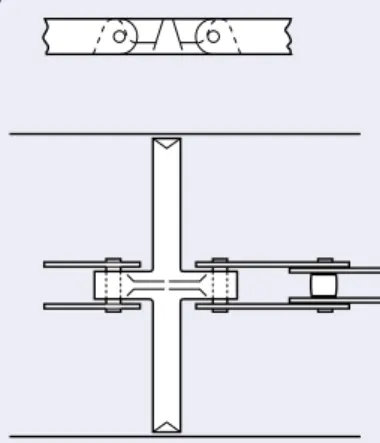
Renold conveyor chain is made up of a series of inner and outer links. Each link comprises components manufactured from materials best suited to their function in the chain; the various parts are shown in Figure 1. An inner link consists of a pair of inner plates which are pressed onto cylindrical bushes, whilst on each bush a free fitting roller is normally assembled. Each outer link has a pair of outer plates which are pressed onto bearing pins and the ends of the pins are then rivetted over the plate.
From the foregoing, it will be seen that a length of chain is a series of plain journal bearings free to articulate in one plane. When a chain articulates under load the friction between pin and bush, whilst inherently low because of the smooth finish on the components, will tend to turn the bush in the inner plates and similarly the bearing pin in the outer plate. To prevent this the bush and pin are force fitted into the chain plates. Close limits of accuracy are applied to the diameters of plate holes, bushes and bearing pins, resulting in high torsional security and rigidity of the mating components. Similar standards of accuracy apply to the pitch of the holes in the chain plates.
To ensure optimum wear life the pin and bush are hardened. The bush outside diameter is hardened to contend with the load carrying pressure and gearing action, both of which are imparted by the chain rollers. Chain roller material and diameter can be varied and are selected to suit applicational conditions; guidance in roller selection is given on page 73. Materials used in chain manufacture conform to closely controlled specifications. Manufacture of components is similarly controlled both dimensionally and with regard to heat treatment.
For a given pitch size of transmission chain, there is normally a given breaking load. However, conveyor chain does not follow this convention. For each breaking load, conveyor chain has multiple pitch sizes available. The minimum pitch is governed by the need for adequate sprocket tooth strength, the maximum pitch being dictated by plate and general chain rigidity. The normal maximum pitch can be exceeded by incorporating strengthening bushes between the link plates, and suitable gaps in the sprocket teeth to clear these bushes.
CHAIN TYPES
There are two main types of conveyor chain - hollow bearing pin and solid bearing pin.
Hollow Bearing Pin Chain
Hollow pin conveyor chain offers the facility for fixing attachments to the outer links using bolts through the hollow pin and
attachment, this method of fixing being suitable for use in most normal circumstances. The attachments may be bolted up tight or be held in a ‘free’ manner. Bolted attachments should only span the outer link as a bolted attachment spanning the inner link would impair the free articulation of the chain.
RENOLD
4
Solid Bearing Pin Chain
Solid bearing pin chain, while having exactly the same gearing dimensions in the BS series of chain as the equivalent hollow pin chain, i.e.pitch, inside width and roller diameter, is more robust with a higher breaking load and is recommended for use where more arduous conditions may be encountered.
Deep Link Chain
Hollow and solid pin chain has an optional side plate design known as deep link. This chain’s side plates have greater depth than normal, thus providing a continuous carrying edge above the roller periphery.
INTERNATIONAL STANDARDS
Conveyor chain, like transmission chain, can be manufactured to a number of different international standards. The main standards available are:British Standard - BS
This standard covers chain manufactured to suit the British market and markets where a strong British presence has dominated engineering design and purchasing. The standard is based on the original Renold conveyor chain design.
ISO Standard
Chain manufactured to ISO standards is not interchangeable with BS or DIN standard chain. This standard has a wide acceptance in the European market, except in Germany. Chain manufactured to this standard is becoming more popular and are used extensively in the Scandinavian region.
CHAIN ATTACHMENTS
An attachment is any part fitted to the basic chain to adapt it for a particular conveying duty, and it may be an integral part of the chain plate or can be built into the chain as a replacement for the normal link.
K Attachments
These are the most popular types of attachment, being used on slat and apron conveyors, bucket elevators etc. As shown in Fig. 2 they provide a platform parallel to the chain and bearing pin axes. They are used for securing slats and buckets etc. to the chain. Either one or two holes are normally provided in the platform, being designated K1 or K2 respectively. K attachments can be incorporated on one or both sides of the chain. For the more important stock pitches where large quantities justify the use of special manufacturing equipment, the attachments are produced as an integral part of the chain, as shown in Fig. 2(a). Here the platform is a bent over extension of the chain plate itself.
On other chain or where only small quantities are involved, separate attachments are used, as shown in Fig. 2(b). These are usually welded to the chain depending on the particular chain series and the application. Alternatively, (see Fig 2(c)), K attachments may be bolted to the chain either through the hollow bearing pins, or by using special outer links with extended and screwed bearing pin ends.
(a) K1 bent over attachment.
(b) K1 attachment, welded to link plate.
(c) K2 attachment bolted through hollow bearing pin.
F Attachments
These attachments as shown in Fig. 3 are frequently used for pusher and scraper applications. They comprise a wing with a vertical surface at right angles to the chain. They can be fitted to one or both sides and are usually secured by welding. Each wing can be provided with one or two holes, being designated F1 or F2 respectively.
(a) F1 attachments welded to link plates on one or both sides of the chain as required.
(b) F2 attachments welded to link plates on one or both sides of the chain as required.
Spigot Pins and Extended
Bearing Pins
Both types are used on pusher and festoon conveyors and tray elevators, etc. Spigot pins may be assembled through hollow bearing pins, inner links or outer links. When assembled through link plates a spacing bush is necessary to ensure that the inside width of the chain is not reduced. Gapping of the sprocket teeth is necessary to clear the bush.
Solid bearing pin chains can have similar extensions at the pitch points by incorporating extended pins. Both spigot pins and extended pins, as shown in Fig. 4, can be case-hardened on their working diameters for increased wear resistance.
(a) Spigot pin assembled through outer or inner link. (b) Spigot pin bolted through hollow bearing pin. (c) Extended bearing pin.
RENOLD RENOLD RENOLD RENOLD RENOLD RENOLD RENOLD RENOLD RENOLD RENOLD RENOLD RENOLD RENOLD RENOLD
c
Fig. 2 Fig. 3 Fig. 4a
b
c
a
b
a
b
4
Staybars
Types of mechanical handling equipment that use staybars are pusher, wire mesh, festoon conveyors, etc., the staybars being assembled in the same manner as spigot pins. When assembled through link plates a spacing bush and gapping of the sprocket teeth are necessary.
The plain bar-and-tube type shown in Fig. 5 has the advantage that the staybar can be assembled with the chain in situ by simply threading the bar through the chain and tube. The shouldered bar type has a greater carrying capacity than the bar-and-tube type. Staybars are normally used for either increasing overall rigidity by tying two chains together, maintaining transverse spacing of the chains, or supporting loads.
(a) Staybar bolted through hollow bearing pin. (b) Staybar assembled through outer or inner link.
G Attachments
As shown in Fig. 6 this attachment takes the form of a flat surface positioned against the side of the chain plate and parallel to the chain line. It is normally used for bucket elevators and pallet conveyors. When the attachment is integral with the outer plate then the shroud of the chain sprocket has to be removed to clear the plate. G Attachments are normally fitted only to one side of the chain.
(a) G2 attachment outer plate.
(b) G2 attachment, welded or rivetted to link plate.
L Attachments
These have some affinity with the F attachment, being in a similar position on the chain. A familiar application is the box scraper conveyor. As shown in Fig. 7 the attachments are integral with the outer plates, being extended beyond one bearing pin hole and then bent round. The attachments can be plain or drilled with one or two holes, being designated L0, L1 or L2 respectively. They can be supplied on one or both sides of the chain. With this type of attachment the chain rollers are normally equal to the plate depth, or a bush chain without rollers is used.
L2 attachments on both sides of the outer link.
S and Pusher Attachments
These are normally used on dog pusher conveyors. As shown in Fig. 8 the S attachment consists of a triangular plate integral with
attachments are intended for lighter duty, but for heavier duty a pair of attachments on one link is connected by a spacer block to form a pusher attachment. This increases chain rigidity and pushing area.
(a) S attachment outer plate; assembled on one or both sides of chain as required.
(b) Pusher attachment.
Drilled Link Plates
Plates with single holes as shown in Fig. 9(a) are associated with the fitting of staybars or spigot pins. Where G or K attachments are to be fitted then link plates with two holes as shown in Fig. 9(b) are used. Where attachments are fitted to inner links then countersunk bolts must be used to provide sprocket tooth clearance.
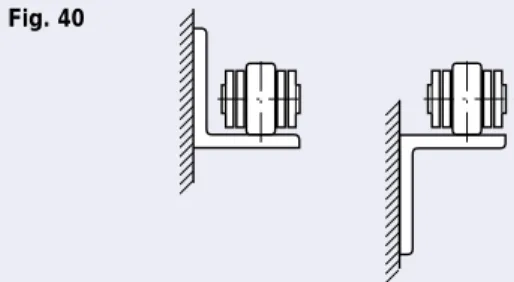
Outboard Rollers
The main reasons for using outboard rollers are that they increase roller loading capacity of the chain and provide a stabilised form of load carrier. As shown in Fig. 10 the outboard rollers are fixed to the chain by bolts which pass through hollow bearing pins. Outboard rollers have the advantage that they are easily replaced in the event of wear and allow the chain rollers to be used for gearing purposes only.
Chain Joints
Conveyor chain is normally supplied in convenient handling lengths, these being joined by means of outer connecting links. This can be accomplished by the use of any of the following:
No. 107 No. 69 RENOLD RENOLD RENOLD RENOLD RENOLD RENOLD RENOLD RENOLD
Outer link used for rivetting chain endless. It is particularly useful in hollow bearing pin chains where the hollow pin
Bolt-type connecting link with solid bearing pin. Loose plate is a slip fit on the bearing pins and retained by self
Fig. 5
Fig. 6
Fig. 7
Fig. 8
Fig. 9
Fig. 10 Outboard rollers.
Fig. 11
a
b
a
b
a
b
4
Advantages of Renold Conveyor
Chain
These can be summarised as
follows:-a. Large bearing areas and hardened components promote maximum life.
b. Low friction due to a smooth finish of the components. c. The inclusion of a chain roller and the high strength to
weight ratio enable lighter chain selection and lower power consumption.
d. The use of high grade materials ensures reliability on onerous and arduous applications.
e. The facility to obtain a variety of pitches with each chain breaking strength and a variation in attachment types provides adaptability.
f. The accuracy of components provides consistency of operation, accurate gearing and low sprocket tooth wear. The latter is particularly important in multistrand systems where equal load distribution is vital.
BASIC REQUIREMENTS
To enable the most suitable chain to be selected for a particular application it is necessary to know full applicational details such as the following:Type of conveyor.
Conveyor centre distance and inclination from the horizontal. Type of chain attachment, spacing and method of fixing to the chain.
Number of chains and chain speed.
Details of conveying attachments, e.g. weight of slats, buckets, etc. Description of material carried, i.e. weight, size and quantity. Method of feed and rate of delivery.
Selection of Chain Pitch
In general the largest stock pitch possible consistent with correct operation should be used for any application, since economic advantage results from the use of the reduced number of chain components per unit length. Other factors include size of bucket or slats etc., chain roller loading (see Page 73) and the necessity for an acceptable minimum number of teeth in the sprockets where space restriction exists.
CHAIN PULL CALCULATIONS
The preferred method of calculating the tension in a conveyor chain is to consider each section of the conveyor that has a different operating condition. This is particularly necessary where changes in direction occur or where the load is not constant over the whole of the conveyor.For uniformly loaded conveyors there is a progressive increase in chain tension from theoretically zero at A to a maximum at D. This is illustrated graphically in Fig. 14 where the vertical distances represent the chain tension occurring at particular points in the circuit, the summation of which gives the total tension in the chain.
Thus, in Fig. 14 the maximum pull at D comprises the sum of: (a) Pull due to chain and moving parts on the unloaded side. (b) Extra pull required to turn the idler wheels and shaft. (c) Pull due to chain and moving parts on the loaded side. (d) Pull due to the load being moved.
If it is imagined that the chains are ‘cut’ at position X then there will be a lower load pull or tension at this position than at Y. This fact is significant in the placing of caterpillar drives in complex circuits and also in assessing tension loadings for automatic take-up units.
This principle has been used to arrive at the easy reference layouts and formulae (Page 80 - 81) to which most conveyor and elevator applications should conform. Where conveyors do not easily fit these layouts and circuits are more complex then see page 82 or consult Renold Applications Department for advice.
FACTORS OF SAFETY
Chain manufacturers specify the chain in their product range by breaking load. Some have quoted average breaking loads, some have quoted minimum breaking loads depending upon their level of confidence in their product. Renold always specify minimum breaking load. To obtain a design working load it is necessary to apply a “factor of safety” to the breaking load and this is an area where confusion has arisen.
As a general rule, Renold suggest that for most applications a factor of safety of 8 is used,
Working Load = Breaking Load
8 On lower breaking strength
chain a soft circlip retains the connecting plate in position on the pins, the connecting plate being an interference fit on the bearing pins.
A modified version of the bolt-type connecting link. The connecting pins are extended to permit the fitment of attachments on one side of the chain only.
Travel C B Y D Driver Total chain tension
X A
For 4,500 lbf series chain only, circlips are fitted to both ends of hollow connecting pins.
Similar to No. 86 but allows attachments to be bolted to both sides of the chain. Fig. 12
Fig. 14 Fig. 13
No. 58 No. 86
4
On first inspection, a factor of safety of 8 seems very high and suggests that the chain could be over-selected if this factor is applied.
If, however, we examine the situation in detail, the following points
arise:-1. Most chain side plates are manufactured from low or medium carbon steel and are sized to ensure they have adequate strength and resistance to shock loading.
2. These steels have yield strengths that vary from 50% to 65% of their ultimate tensile strength. This means that if chains are subjected to loads of 50% to 65% of their breaking load, then permanent pitch extension is likely to occur.
3. It is the tendency to over-select drive sizes “just to be sure the drive is adequate”, and the motors used today are capable of up to 200% full load torque output for a short period.
4. The consequences of this are that a chain confidently selected with a factor of safety of 8 on breaking load is in effect operating with a factor of safety of as low as 4 on the yield of the material, and 2 when the possible instantaneous overload on the drive is considered, and this is without considering any over-selection of the motor nominal power.
5. A further consideration when applying a factor of safety to a chain application is the chain life.
The tension applied to a chain is carried by the pin/bush interface which at the chain sprockets articulates as a plain bearing.
Experience has shown that, given a good environment, and a clean and well lubricated chain, a bearing pressure of up to 24N/mm2
(3500 lb/inch2) will give an acceptable pin/bush life. A safety factor of
8 will give this bearing pressure.
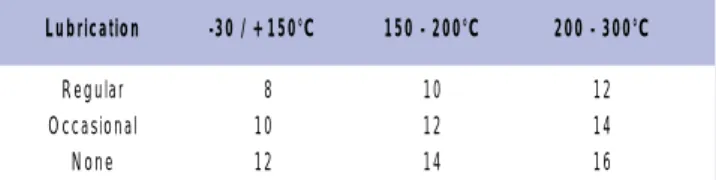
In anything other than a clean well lubricated environment the factor of safety should be increased, thus lowering the bearing pressure, if some detriment to the working life of the chain is to be avoided. Table 1 gives a general guide to the appropriate safety factors for different applications.
Table 1 - Factors of Safety
CLEANLINESS/LUBRICATIONTEMPERATURE/LUBRICATION
In all the listed applications and conditions, the increase in factor of safety is applied with the object of lowering the pin/bush bearing pressure to improve the chain life.
CHAIN LIFE
There are a number of factors affecting the life of a chain in a particular environment.
a. The load on the chain and therefore the bearing pressure between the pin and the bush.
The design of conveyor chain is such that at the calculated working load of the chain (relative to the breaking load) then the bearing pressure between the pin and the bush will be at a maximum of 24N/mm2(3500lb/in2) for a clean well lubricated environment.
This pressure should be reduced for anything less than clean, well lubricated conditions and this is allowed for by increasing the factor of safety as shown in table 1.
b. The characteristics of the material handled, i.e. abrasiveness, etc.
Some materials are extremely abrasive and if the material cannot be kept away from the chain then the bearing pressure must be reduced to lessen the effect of the abrasion. It is possible to improve the abrasion resistance of chain components by more sophisticated heat treatments at extra cost but the usual way of ensuring an acceptable life is to reduce the bearing pressure. See page 98 for the abrasive characteristics of materials. In some instances it is possible to use block chain to improve chain life, see page 88. c. Corrosion.
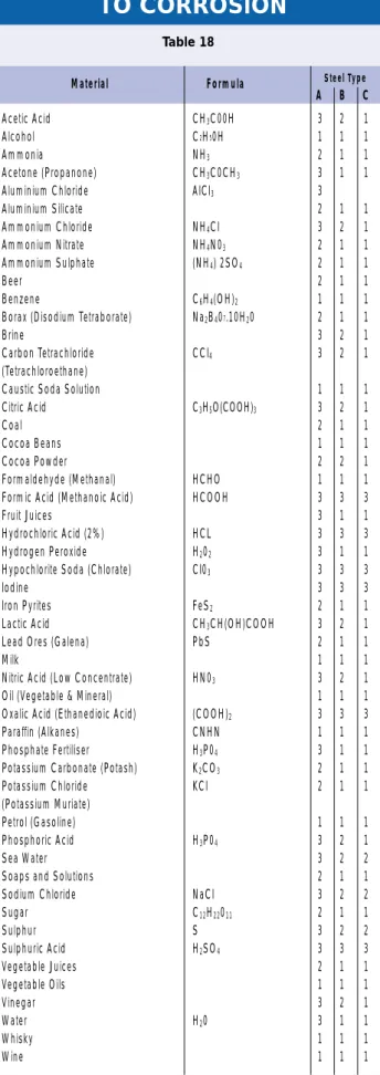
Some materials are aggressive to normal steels and the nature of the attack will be to reduce the side plate section and therefore the chain strength, or cause pitting of the pin, bush and roller surfaces.
The pitting of the surface has the effect of reducing the bearing area of the component and therefore increasing the bearing pressure and wear rate. The process will also introduce (onto the bearing surfaces) corrosion products which are themselves abrasive.
Materials such as Nitrates will cause the failure of stressed components due to nitrate stress cracking.
Page 104 shows some materials together with their corrosive potential for various chain materials.
d. Maintenance by the end user is one of the most important factors governing the life of a chain.
For the basic maintenance measures required to obtain the maximum useful life from your chain consult the Installation and Maintenance section.
LO AD EXTENSION MATERIAL YIELD, POINT P O (a) EXTENSION PERMANENT Fig. 15 Lubrication -30 / +150°C 150 - 200°C 200 - 300°C Regular 8 10 12 Occasional 10 12 14 None 12 14 16 Regular 8 10 12 14 Occasional 10 12 14 16 None 12 14 16 18
Lubrication Clean Moderately Dirty Abrasive Clean
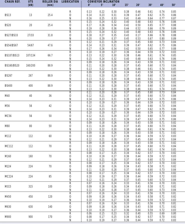
BS Series BS13 13 25.4 0.13 0.14 0.16 BS20 20 25.4 0.15 0.17 0.19 BS27/BS33 27/33 31.8 0.15 0.18 0.20 BS54/BS67 54/67 47.6 0.12 0.14 0.17 BS107/BS134 107/134 66.7 0.10 0.13 0.15 BS160/BS200 160/200 88.9 0.09 0.11 0.13 BS267 267 88.9 0.09 0.11 0.13 BS400 400 88.9 0.09 0.11 0.13 ISO Series M40 40 36 0.11 0.12 0.14 M56 56 42 0.10 0.12 0.14 MC56 56 50 0.10 0.12 0.14 M80 80 50 0.09 0.11 0.13 M112 112 60 0.09 0.10 0.12 MC112 112 70 0.09 0.11 0.13 M160 160 70 0.08 0.10 0.12 M224 224 85 0.08 0.09 0.11 MC224 224 100 0.08 0.10 0.12 M315 315 100 0.07 0.09 0.11 M450 450 120 0.07 0.09 0.10 M630 630 140 0.07 0.09 0.10 M900 900 170 0.06 0.08 0.10
Chain Ultimate Roller Chain Overall Coefficient of Friction µc
Reference Strength Diameter
(kN) (mm) Regular Occasional No D Lubrication Lubrication Lubrication
µF= 0.15 µF= 0.20 µF= 0.25
4
ASSESSMENT OF CHAIN
ROLLER FRICTION
In conveyor calculations the value of the coefficient of friction of the chain roller has a considerable effect on chain selection. When a chain roller rotates on a supporting track there are two aspects of friction to be considered. Firstly there is a resistance to motion caused by rolling friction and the value for a steel roller rolling on a steel track is normally taken as 0.00013. However this figure applies to the periphery and needs to be related to the roller diameter, therefore:
Coefficient of rolling friction =
0.00013 = 0.13 = 0.26
Roller radius (m) Roller radius (mm) Roller diameter (mm) Secondly a condition of sliding friction exists between the roller bore and the bush periphery. For well lubricated clean conditions a coefficient of sliding friction µFof 0.15 is used and for poor lubrication
approaching the unlubricated state, a value of 0.25 should be used. Again this applies at the bush/roller contact faces and needs to be related to their diameters.
Coefficient of sliding friction =
µF x Roller bore (mm)
Roller diameter (mm)
Thus the overall theoretical coefficient of chain rollers moving on a rolled steel track =
0.26 + (µFx Roller bore) (mm)
Roller diameter (mm)
In practice, a contingency is allowed, to account for variations in the surface quality of the tracking and other imperfections such as track joints. The need for this is more evident as roller diameters become smaller, and therefore the roller diameter is used in an additional part of the formula, which becomes:
Overall coefficient of friction =
µc= 0.26 + (µFx d) + 1.64
D D
and simplified: µc = 1.90 + µF d
D
Where µc = overall coefficient of friction for chain. µF = bush/roller sliding friction coefficient.
d = roller bore diameter in mm. D = roller outside diameter in mm.
The formula is applicable to any plain bearing roller but in the case of a roller having ball, roller or needle bearings the mean diameter of the balls etc. (Bd), would be used as the roller bore. µFis taken as 0.0025 to 0.005, the latter being assumed to apply
to most conditions. Thus overall coefficient of friction for a chain roller fitted with ball bearings and rolling on a steel track: µc= 0.26 + (0.005 x Mean diameter of balls (mm)) + 1.64
Roller diameter (mm) Roller diameter (mm) ... µc= 1.90 + (0.005 x Bd)
D
The following table shows values for overall coefficient of friction for standard conveyor chain with standard rollers (µc). Alternative values can be calculated as above if the roller diameter is modified from the standard shown.
OVERALL COEFFICIENTS OF ROLLING FRICTION FOR STANDARD CONVEYOR CHAIN (µc)
D d Chain Pull Sliding Friction Rolling Friction Bush/Roller clearance (exaggerated) Roller Bush Bd Table 2 Fig. 16 Fig. 17 µF
4
ROLLER SELECTION AND
ROLLER LOADING
CONSIDERATIONS
Roller Selection
Roller Materials1. Unhardened mild steel rollers are used in lightly loaded, clean and well lubricated applications subject to occasional use. 2. Hardened steel rollers are used in the majority of applications
where a hard wearing surface is required.
Note that through hardened sintered rollers are standard on BS chain of 26 to 67KN breaking load. On all other BS and on ISO chain the standard hardened rollers are in case hardened mild steel.
3. Cast iron rollers are used in applications where some corrosion is likely and a measure of self-lubrication is required.
4. Synthetic rollers, e.g. Delrin, nylon or other plastics can be used where either noise or corrosion is a major problem. Please enquire.
Roller Sizes and Types
1. Small (gearing) rollers are used for sprocket gearing purposes only to reduce abrasion and wear between chain bush and sprocket tooth. These rollers do not project and consequently, when not operating vertically, the chain will slide on the side plate edges.
2. Standard projecting rollers are used for most conveying applications and are designed to operate smoothly with optimum rolling friction properties. They create an acceptable rolling clearance above and below the chain side plates. 3. Flanged rollers are used where extra guidance is required or
where imposed side loads would otherwise force the chain out of line.
4. Larger diameter rollers are occasionally used where the greater diameter of the roller reduces wear by reducing the rubbing velocity on the chain bushes and promotes smoother running at slow speeds.
These rollers can be either plain or flanged in steel, cast iron or synthetic material.
5. Most chain can be supplied with ball bearing rollers either outboard or integral. This special design option can be justified by the selection of a lower breaking load chain in many applications and a reduction in the drive power required.
Roller Loading (Bush/Roller
Wear)
In the majority of cases a conveyor roller chain will meet bush/roller wear requirements if it has been correctly selected using factors of safety on breaking load. Doubt can arise where heavy unit loading is involved, which could cause the bearing pressure between the chain bush and roller to be excessively high, or where the chain speed may exceed the recommended maximum. In such cases further checks have to be made.
Bush/Roller Bearing Areas and
Bearing Pressures
The bush/roller bearing areas for standard BS and ISO series conveyor chain are as follows:
Bush/Roller Bearing Area – BS
Chain Reference Bearing Area mm2
BS13 99 BS20 143 BS27 254 BS33 254 BS54 420 BS67 420 BS107 803 BS134 803 BS160 1403 BS200 1403 BS267 1403 BS400 1403 Table 3
Bush/Roller Bearing Area - ISO
Chain Reference Bearing Area mm2
M40 232 M56 333 MC56 447 M80 475 M112 630 MC112 850 M160 880 M224 1218 MC224 1583 M315 1634 M450 2234 M630 3145 M900 4410 Table 3 (Continued)
Bearing Pressure
Normal maximum permitted bearing pressures for chain speeds up to 0.5m/sec., and in reasonably clean and lubricated applications are listed below:
Roller Bearing Pressure P
Material Normal Maximum
Mild steel case hardened 1.8N/mm2
Sintered steel through hardened 1.2N/mm2
Cast iron 0.68N/mm2
Table 4
The formula: bearing pressure P (N/mm2) = roller load R (N)
Bearing area BA (mm2)
is used first to check whether actual pressure exceeds the above recommendation. If it does, or if the conveyor speed exceeds 0.5m/sec, the chain may still be acceptable if alternative conditions can be met. These depend upon a combination of bearing pressure and rubbing speed between bush and roller, known as the PVRvalue, and the degree of cleanliness and
lubrication on the application. If cleanliness and lubrication are much better than average for example, higher bearing pressures and PVRvalues than normal can be tolerated. In order to make
4
Rubbing Speed VR(m/sec) =
Chain Speed (m/sec) x Bush diameter (mm) Roller Diameter (mm)
Table 5
If the rubbing speed is above 0.15 m/s, calculate the PV value to see if it is below the max value in the table. If the rubbing speed is below 0.15 calculate the bearing pressure to see if it is below the maximum given in the table. If the speed is below 0.025 m/s it is best to use rollers with an o/d to bore ratio of 3 or higher, or use ball bearing inboard or outboard rollers with the required load capacity.
If the calculated bearing pressure or PV exceeds the guidelines given in the tables then consider one of the following:
a. Use a larger chain size with consequently larger rollers. b. Use larger diameter rollers to reduce the rubbing speed. c. Use outboard rollers, either plain or ball bearing. d. Use ball bearing rollers.
e. If in doubt consult Renold.
‘STICK-SLIP’
‘Stick-Slip’ is a problem that occurs in some slow moving conveyor systems which results in irregular motion of the chain in the form of a pulse. Stick slip only occurs under certain
conditions and the purpose of this section is to highlight those conditions to enable the problem to be recognised and avoided. For a conveyor running at a linear speed of approx. 0.035m/sec or less, one of the most often encountered causes of stick-slip is over-lubrication of the chain. Too much oil on the chain leads to the chain support tracks being coated with oil thus lowering µR1, (Fig. 18). If any of the other stick-slip conditions are present then µR1is insufficient to cause the roller to turn against the roller/bush friction µF and the roller slides along on a film of oil.
The oil film builds up between the bush and roller at the leading edge of the pressure contact area and the resulting vacuum condition between the two surfaces requires force to break it down. If the chain tracks are coated with oil, or oil residue, then this force is not immediately available and the roller slides along the track without rotating. The vacuum then fails, either due to the static condition of the bush/roller surfaces or by the breakdown of the dynamic film of lubricant on the track.
In either case the change from the sliding state to rotation causes a pulse as the velocity of the chain decreases and then increases. Once rotation returns then the cycle is repeated causing regular pulsations and variations of chain speed. Although the friction is insufficient to cause the roller to turn, friction is present and, over a period, the roller will develop a series of flats which will compound the problem.
The other features that are necessary for stick slip to occur are: a. Light loading - If the loading on the roller is very light then it is
easy for a vacuum condition to develop. Heavy loads tend to break the oil film down on the chain tracks.
b. Irregular loading - If the chain is loaded at intervals, with unloaded gaps, it is possible for the chain between the loads to experience stick slip due to light loading.
Precautions to Avoid Stick Slip
1. Avoid speeds in the critical range up to approx. 0.035m/sec.,if possible.
2. Avoid irregular loading, if possible.
3. If it is not possible to avoid the speed and loading criticality, then great care should be taken in system design:
3.1 Control the application of lubricant to avoid track contamination.
3.2 If light loads are to be carried then chain rollers should be either larger than standard or be fitted with ball bearings to lower the bush/roller friction, µF, or improve mechanical efficiency.
As a rough guide, where plain (not ball bearing) rollers are used, a ratio of roller diameter to bush diameter of 2.7:1 or greater should eliminate stick slip at the critical speeds.
TRACKED BENDS
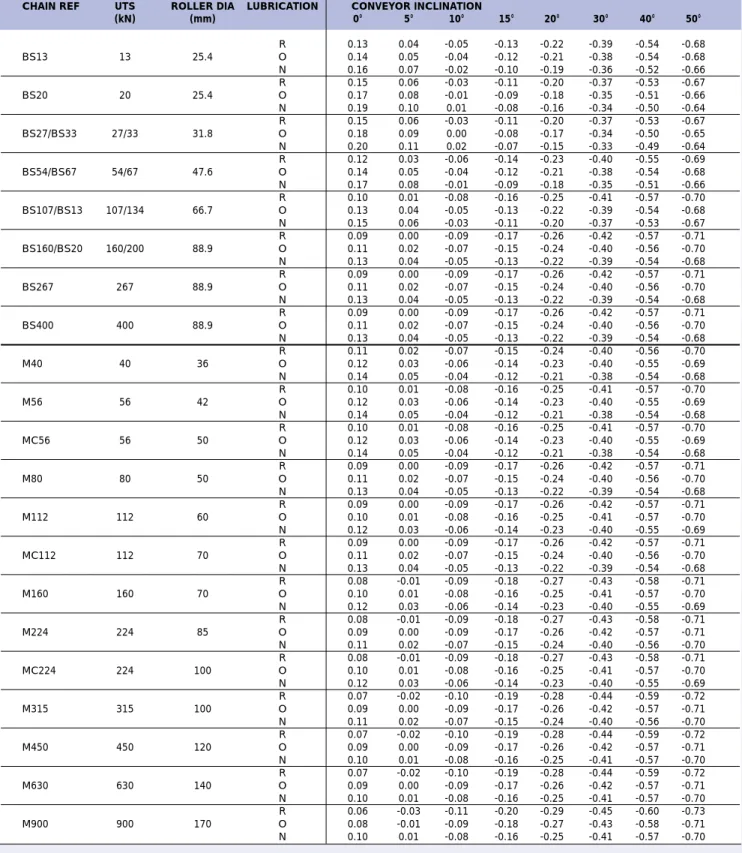
Where chain is guided around curves there is an inward reaction pressure acting in the direction of the curve centre. This applies whether the curved tracks are in the vertical or horizontal planes, and, relative to the former, whether upwards or downwards in direction. The load pull effect resulting from the chain transversing a curved section, even if this be in the vertical downward direction, is always considered as a positive value, i.e. serving to increase the chain load pull.
An analogy is a belt on a pulley whereby the holding or retaining effect depends upon the extent of wrap-around of the belt, and friction between the belt and pulley.
Similarly there is a definite relationship between the tension or pull in the chain at entry and exit of the curve. Referring to the diagrams this relationship is given by:
P2= P1eµcθ
Where P1 = Chain pull at entry into bend (N) P2 = Chain pull at exit from bend (N) e = Naperian logarithm base (2.718)
µc = Coefficient of friction between chain and track θ = Bend angle (radians)
Case hardened 0.025 - 0.15 0.025 - 0.25 10.35 1.80 mild steel over 0.15 over 0.25 use PVR =1.55 use PVR =0.45
Sintered through- 0.025 - 0.15 0.025 - 0.25 6.90 1.20 hardened steel over 0.15 over 0.25 use PVR =1.04 use PVR =0.30
Cast iron 0.025 - 0.15 0.025 - 0.25 3.91 0.68 over 0.15 over 0.25 use PVR =0.59 use PVR =0.17
Bush/Roller Clearance (Exaggerated) Roller Bush F od W (kg) µ F µ R 1 id Fig. 18
Roller Rubbing speed Max. Bearing Pressure Material VR(m/sec) P (N/mm2)
Very Good Average Very Good Average Conditions Conditions Conditions Conditions
4
The above formula applies whether the chain is tracked via the chain rollers or by the chain plate edges bearing on suitable guide tracks. Table 6 gives values of eµcθ.
Since high reaction loadings can be involved when negotiating bend sections it is usually advisable to check the resulting roller loading. This can be done from the following formula where RLis
the load per roller due to the reaction loading at the bend section.
RL(N) = P2(N) x Chain Pitch (mm)
Chain curve radius (mm)
The reaction loading value obtained should then be added to the normal roller load and the total can be compared with the permitted values discussed in the section on roller selection and roller loading considerations.
There is a minimum radius which a chain can negotiate without fouling of the link plate edges. Relevant minimum radii against each chain series are listed in table 7 on page 76, and it will be noted that these will vary according to pitch, roller diameter and plate depth. P2 P1 θ P2 P1 P1 P2 VERTICAL PLANE DOWNWARDS VERTICAL PLANE UPWARDS HORIZONTAL PLANE θ θ
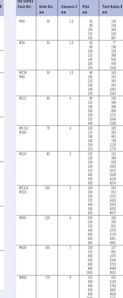
MINIMUM TRACK RADIUS FOR LINK CLEARANCE
Values of eµcθfor variable Values of µcθ
µcθ eµcθ µcθ eµcθ µcθ eµcθ 0.02 1.0202 0.25 1.2840 0.45 1.5683 0.04 1.0408 0.26 1.2969 0.46 1.5841 0.06 1.0618 0.27 1.3100 0.47 1.6000 0.08 1.0833 0.28 1.3231 0.48 1.6161 0.29 1.3364 0.49 1.6323 0.10 1.1052 0.30 1.3499 0.50 1.6487 0.11 1.1163 0.31 1.3634 0.56 1.8221 0.12 1.1275 0.32 1.3771 0.57 2.0138 0.13 1.1388 0.33 1.3910 0.58 2.2255 0.14 1.1505 0.34 1.4050 0.59 2.4596 0.15 1.1618 0.35 1.4191 1.0 2.7183 0.16 1.1735 0.36 1.4333 1.1 3.0042 0.17 1.1835 0.37 1.4477 1.2 3.3201 0.18 1.1972 0.38 1.4623 1.3 3.6693 0.19 1.2092 0.39 1.4770 1.4 4.0552 0.20 1.2214 0.40 1.4918 1.5 4.4817 0.21 1.2337 0.41 1.5068 1.6 4.9530 0.22 1.2461 0.42 1.5220 1.7 5.4739 0.23 1.2586 0.43 1.5373 1.8 6.0497 0.24 1.2712 0.44 1.5527 1.9 6.6859 2.0 7.3891 Table 6 C R C R Fig. 19
4
Minimum Track Radii for BS and ISO Series Chain
Table 7 BS13 25.4 1.3 38.10 60 50.80 115 63.50 190 76.20 280 88.90 380 101.60 500 114.30 635 BS20 25.4 1.3 38.10 90 50.80 160 63.50 255 76.20 375 BS27 31.8 1.3 50.80 160 BS33 63.50 255 76.20 370 88.90 510 101.60 670 114.30 845 127.00 1050 139.70 1270 152.40 1500 BS54 47.6 2.5 76.20 305 BS67 88.90 425 101.60 560 114.30 720 127.00 890 152.40 1295 177.80 1755 203.20 2300 228.60 2920 BS107 66.7 4 101.60 295 BS134 127.00 480 152.40 710 165.10 830 177.80 970 203.20 1280 228.60 1630 254.00 2020 304.80 2920 BS160 88.9 5 127.00 185 BS200 152.40 285 BS267 177.80 400 203.20 540 228.60 690 254.00 860 304.80 1250 381.00 1980 457.20 2870 BS400 88.9 5 152.40 335 228.60 810 304.80 1470 381.00 2320 457.20 3350 609.60 5990 M40 36 1.3 63 136 80 218 100 340 125 530 160 867 M56 50 2.5 63 77 80 138 100 228 125 368 160 618 200 978 250 1540 MC56 50 2.5 80 163 M80 100 253 125 393 160 643 200 1003 250 1565 M112 60 4 80 106 125 299 160 506 200 806 250 1275 315 2040 400 3306 MC112 70 4 100 182 M160 125 283 160 461 200 718 250 1120 315 1775 M224 85 5 125 222 160 388 200 628 250 1003 315 1615 400 2628 500 4128 630 6576 MC224 100 5 160 593 M315 200 953 250 1515 315 2433 400 3953 500 6202 630 9875 M450 120 6 200 304 250 505 315 833 400 1376 500 2179 630 3491 800 5661 M630 140 7 250 537 315 891 400 1475 500 2340 630 3753 800 6090 1000 9552 M900 170 8 315 653 400 1100 500 1762 630 2842 800 4629 1000 7276 BS SERIESChain Ref. Roller Dia. Clearance C Pitch Track Radius R
mm mm mm mm
ISO SERIES
Chain Ref. Roller Dia. Clearance C Pitch Track Radius R
4
MATCHING OF CONVEYOR CHAIN
Any application in which two or more strands of chain are required to operate side by side may require the strands to be matched. This would be to maintain the same fixed relationship between handling lengths throughout the length of the chains. Due to manufacturing tolerances on chain components actual chain length may vary within certain limits. Thus, two strands of any given pitch length would not necessarily have the same actual overall length if chosen at random. Also, different sections along any chain length may vary within the permissible limits and therefore, even given identical overall lengths, corresponding sections of random strands would be slightly out of register. These displacements tend to become more pronounced with increasing length.CONVEYOR TYPES
The types of conveyors where this is likely to have the greatest effect are:
1) Where chains are very close and tied together, i.e.
within approximately 300/500mm depending on breaking load. 2) On very long or long and complex circuits.
3) Where load positioning / orientation at load or unload is important.
PROCEDURE
The procedure used for matching conveyor chain is as follows:-a) Each handling length is accurately measured and
numbered.
b) A list is produced (for a two chain system) of chains, e.g A and B, in which handling lengths placed opposite each other are as near equal in length as possible.
c) This list will give a series of lengths in which A and B are matched, A1with B1, A2with B2, etc.
d) The chains are then tagged with a brass tag
containing the appropriate identity, i.e. A2B4etc and, where
required, the chain length.
ON-SITE ASSEMBLY
When assembling the chain on site it is important that lengths A and B are installed opposite each other as are A1, and B1, etc.
ATTACHMENTS
It should be noted that chains can only be matched as regards the chain pitch length. Due to extra tolerances involved in attachment positioning and holing it is not possible to match chains relative to attachments.
SPROCKETS
Where chains have been matched, the drive sprockets should not only be bored and keywayed as a set in relation to a tooth, as in a normal conveyor drive, but it is recommended that a machine cut tooth form is also used to ensure equal load sharing.
ACCURACY
In order to maintain the accuracy of matched chains it is important to ensure equal tensioning and even lubrication of the chain set.
4
PUSHER CONVEYORS
Where chain is used with pusher attachment plates, to move loads along a separate skid rail (e.g. billet transfer conveyors), then there will be an extra load in the chain due to the reaction in the pushers.This load can be calculated by the following formula: Reaction Load Pull
PL = µm W hu µc
P
Where µm = Coefficient Friction, Load on Steel
µc = Coefficient Friction, Chain Rolling
W = Load (N)
hu = Pusher Height from Chain Pitch Line (mm)
P = Chain Pitch (mm)
If there is more than one pusher and load position then the total reaction load can be found by either multiplying by the total number of loads or by assuming that the total load acts at one pusher. This reaction load pull should then be added to the total chain pull Cp obtained using layout B page 80 and ignoring the term X (side guide friction).
CONVEYING DIRECTLY ON CHAIN
ROLLERS
In some applications, loads are carried directly on the projecting rollers of the chain, instead of on attachments connected to the chain side plates. In this case the loads will travel at twice the speed of the chain.
Where high unit loads are involved the rollers must be either case hardened mild steel or through hardened medium carbon steel. For normal duty the tracks can be standard rolled sections but for heavy unit loads hardened tracks may be necessary. Note: The roller hardness should always be greater than track hardness.
For a layout similar to the above, the chain pull can be calculated as follows:
Where Cp = Total chain pull (N)
W = Weight of material on conveyor (kg) Wc = Weight of chain(s) and attachments (kg/m)
L = Conveyor centres (m)
µR1 = Coefficient of rolling friction between chain
roller and track
µR3 = Coefficient of rolling friction between chain
roller and load
µC = Chain overall coefficient of friction
d = Roller I/D (mm)
D = Roller O/D (mm)
Rolling friction µR1for a steel roller on a rolled or pressed steel
track is variable between 0.051 and 0.13 depending on the track surface condition.
The rolling friction between the roller and the load is also variable depending upon the latter. For many applications it is sufficiently accurate to take µR3as being 0.13.
SIDE FRICTION FACTORS
It must be appreciated that on apron conveyors carrying loose materials, and where static skirt plates are employed, the pressure of material sliding against the skirt will increase the required load pull of the chain.This additional pull is given by the expression: 2.25 x 10⁴GLH2(N)
Where H = the height of the material (m)
L = the length of the loaded section of conveyor (m) G = a factor depending upon the material being
handled. - See page 79 table 8. P h u µm CHAIN PULL TRAVEL CHAIN PITCH LINE W(N) D µ R1 W µR3 d Cp H STATIC SKIRT PLATES
DRIVEN C B W. kg TRAVEL D A DRIVER L
Cp = 9.81 W x 2
(
(
µR1+
2
µR3+
1.64
)
x (1 +
µ
)
c)
+ (2.05 x W x L x
cµ
) N
c D Fig. 20 Fig. 21 Fig. 22 Fig. 224
Ashes, dry, 13mm and under 0.05 0.50
Ashes, wet, 13mm and under 0.02 0.60
Ashes, wet, 75mm and under 0.02 0.60
Cement, Portland 0.09 0.70
Cement, clinker 0.08 0.70
Coal, Anthracite, nuts 0.04 0.50
Coal, Bituminous, slack, wet 0.03 0.70
Coke, sized 13mm 0.02 0.40
Coke, breeze, fine 0.03 0.70
Grain 0.05 0.40
Gravel, dry, screened 0.08 0.50
Lime, ground 0.04 0.40
Lime, pebble 0.07 0.50
Limestone, crushed 0.14 0.90
Sand, dry 0.13 0.60
Sand, damp 0.17 0.90
Sand, foundry, prepared 0.07 0.90
Sawdust 0.01 0.40
Stone, dust 0.09 0.50
Stone, lumps and fines 0.10 0.70
Soda ash (heavy) 0.09 0.62
Sodium carbonate 0.04 0.45
Wood, chips 0.01 0.40
Table 8
Values given are nominal and are for guidance only; they are based on the materials sliding on steel.
METHODS OF SELECTION
1. Examine the diagrams A to K (page 80-81) and select thelayout nearest to the conveyor under consideration. 2. Examine the formulae printed under the selected layout for
the conveyor chain pull (Cp).
3. Identify and allocate values to the elements of the formulae by using the reference list opposite.
4. Calculate a preliminary chain pull using an estimated chain mass.
5. Apply the correct factor of safety for the application from Table 1 page 71. If temperature and type of application affect your selection, then select the highest factor from other relevant sections.
Chain breaking load = Chain Pull Cp x factor of safety. 6. For the chain breaking strength established in the
preliminary calculation, recalculate maximum chain pull Cp using actual chain mass and check the factor of safety obtained.
7. If loads are carried by the chain, then the roller capacity should be checked - page 73.
8. Conveyor headshaft power may be calculated by using the appropriate formula for K which will give the results in Kilowatts.
Note: The power calculated is that required to keep the conveyor moving, not the motor size required. To select a motor, allowance should be made for starting and transmission losses.
9. Headshaft RPM can be calculated after selecting a suitable size of drive sprocket.
RPM = V x 60 PCD x π
where PCD = Pitch circle dia. of sprocket (m). 10. Headshaft torque can be calculated as follows:
Torque = Cp x PCD (Nm) 2
REFERENCE LIST
Cp = Chain pull total (N)L = Centre distance (m) - head- to tail-shaft
Wc = Chain total mass per metre (kg/m) including attachments and fittings.
Wm = Mass of load/metre (kg/m) W = Total carried load (kg)
T = Conveying capacity (Tonnes/Hour) V = Chain speed (m/sec)
µc = Coefficient of friction, chain on steel (sliding or rolling) -see Table 2 page 72.
µm = Coefficient of friction, load on steel. See table 8 opposite. ρ = Load density (kg/m3)
α = Angle of inclination (degrees).
G = Side friction factor. See table 8 opposite. C = Conveyor width (m) H = Material height (m) S = Bucket spacing (m) Vb = Bucket capacity (m3) K = Power at headshaft (kW) Wb = Bucket mass (kg)
X = Extra chain pull due to side guide friction [X = 2.25 x 10⁴GLH2 (N) - See page 78]
PB = Chain pull at B (N). µs1 = (µcx cos α) - sin α µs2 = (µcx cos α) + sin α µsm = (µmx cos α) + sin α
Df = Dredge factor (spaced bkts)(N) = 90 x Vb x ρ S Dredge factor (continuous bkts)(N) = 30 x Vb x ρ
S
J = Chain sag (m)
a = Idler centres (m) NOTE:
m = Metres, N = Newtons, kW = Kilowatts, kg = Kilograms.
}
see appendix 3 page 104-105Material Factor G µm
4
Chain and material sliding
Chain rolling and material sliding
Chain rolling and material carried
Vertical elevator PB= 9.81 x Wc x L x µs1(N) Cp = 9.81 x L [(Wc x µs2) + (Wm x µsm)] + PB+ X (N) PB= 9.81 x Wc x L x µs1(N) Cp = 9.81 x L [(Wc x µs2) + (Wm x µsm)] + PB+ X (N) PB= 9.81 x Wc x L x µs1(N) Cp = 9.81 x µs2[(Wc x L) + W] + PB(N) Cp = 9.81 [(wb x L) + (Wc x L) + (L x Vb x ρ)] + Df (N) K =[(9.81( L/S x Vb x ρ)) + Df] x V 1000 s s (kW) Cp = 9.81 x L [(2 .05 x Wc x µc) + (Wm x µm)] + X (N) Cp = 9.81 x µc[(2.05 x Wc x L ) + W] (N) Cp = 9.81 x µc[(2.05 x Wc x L) + W] (N) Chain and material sliding
Chain rolling and material sliding
Chain rolling and material carried
Chain sliding and material carried
Cp = 9.81 x L [(2.05 x Wc x µc) + (Wm x µm)] + X (N) K =Cp x V 1000 (kW) K =Cp x V 1000 (kW) K =Cp x V 1000 (kW) K =Cp x V 1000 (kW) K =Cp x V 1000 (kW) K =Cp x V 1000 (kW) K =Cp x V 1000 (kW) LAYOUT A LAYOUT E LAYOUT B LAYOUT F LAYOUT C LAYOUT G LAYOUT D LAYOUT H
4
SELECTION EXAMPLE
A continuous slat conveyor, 36 metre centres of head and tail sprockets, is to carry boxed products 650mm x 800mm, of mass 36kg each. 50 boxes will be the maximum load and two chains are required with K attachments at every pitch one side. 152.4mm pitch chain is preferred and the mass of the slats is 15kg/m. Operating conditions are clean and well lubricated. Chain speed would be 0.45 m/sec using 8 tooth sprockets.The example is of chain rolling and material carried, i.e. Layout C, page 80
It is first necessary to carry out a preliminary calculation to arrive at a chain size on which to base the final calculation. A rough assessment of chain mass can be done by doubling the slat mass, and for rolling friction a figure of 0.15 can be used. Mass of Load on Conveyor = 50 x 36 = 1800 kg Mass per Metre of Slats = 15 kg/m
Estimated Mass of Chain = 15 kg/m
Estimated Mass of Chain & Slats = 15 + 15 = 30 kg/m
Preliminary Chain Pull = 9.81x µc[(2.05 x Wc x L)+W ] N = 9.81 x 0.15 [(2.05 x 30 x 36)+1800 ] N = 5907 N
Factor of safety for this application is 8 (from table 1 page 71). ... Minimum Breaking Load Required = 5907 x 8 = 23628 N
2 per chain
As a solid bearing pin chain is preferable for this application then two strands of 152.4 mm pitch BS series, 33000 N (7500 lbf) breaking load chain may be suitable.
Final Calculation
Chain mass + K3 integral attachment one side every pitch = 3.35 kg/m (from chain catalogue)
Mass of Both Chains = 3.35 x 2 = 6.7 kg/m Mass of Chain + Slats = 6.7 + 15 = 21.7 kg/m
µc = 0.15 - taken from table 2 page 72. (Regular lubrication). Cp (Chain pull) = 9.81 x µc[ (2.05 x Wc x L) + W ] N Cp = 9.81 x 0.15 [ (2.05 x 21.7 x 36) + 1800 ] N Cp = 5005 N
Factor of Safety = Breaking load x 2 = 33000 x 2 = 13.19 Total chain pull 5005
Thus the selection is confirmed.
It is now necessary to check the roller loading.
Box = 650 mm long. Load = mass x g (gravity) = 36 x 9.81 = 353 N Load of Chain and Slats over 650 mm = 21.7 x 9.81 x .65
= 138 N Total Load on Rollers = 353 + 138 = 491 N Number of Rollers Supporting Load = 650 x 2 = 8.5
152.4 Load Per Roller = 491 = 58 N
8.5
Bearing Area of Roller (see table 3) = 254 mm2 ... Bearing Pressure of Rollers = 58 = 0.23 N/mm2
254
This is well below the allowable maximum of 1.2 N/mm2(see page 73 table 4 sintered steel) therefore the roller loading is acceptable.
Conclusion
The selection for this application would be 2 strands of 152.4 mm pitch, 33,000N (7500lbf) breaking load BS series chain with standard sintered steel rollers (Chain No. 145240/16) and K3 bent over attachments one side every pitch.
Power required to drive the conveyor would be:
K = Chain pull x Chain speed = Cp x V kW
1000 1000
= 5005 x 0.45 = 2.25 kW
1000
Note: This is the power required at the headshaft to keep the conveyor moving, not the motor size required. Allowance should be made for starting and transmission/gearing losses when selecting a drive motor.
Headshaft RPM required using an 8 tooth (398.2 mm PCD) sprocket would be
RPM = Chain Speed (m/sec) x 60 PCD (m) x π = 0.45 x 60 = 21.6 RPM 0.398 x π Headshaft Torque = Cp x PCD Nm 2 = 5005 x 0.398 2 L Cp J W DRIVE
Cp = 9.81 1.05
(
)
(
)
+ (
µ
x Wc x L) + (
µ
x W)
L x Wc + (Wc x J)
2(N)
8 x J
K = 9.81 0.05
L x Wc + (Wc x J)
2+ (
µ
x Wc x L) + (
µ
x W)
x V (kW)
8 x J
1000
c c c c L Cp W a J L Cp W a JCp = 9.81 1.05 x L a x Wc + (Wc x J) + (
2µ
x Wc x L) + (
µ
x W) (N)
8 x J
a
(
)
K = 9.81 0.05 x L a x Wc + (Wc x J) + (
2µ
x Wc x L) + (
µ
x W) x V (kW)
8 x J
a
(
)
1000
c c c c LAYOUT JChain rolling, material carried. Return strand unsupported.
LAYOUT K
4
CALCULATING COMPLEX
CIRCUITS
For calculating chain pull Cp of complex circuits, which do not conform to one of the layouts A to K (page 80), the following method can be used as a guide, or Renold Applications Department may be contacted.
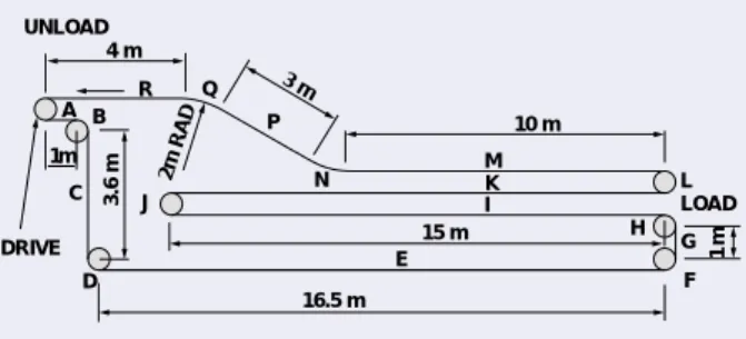
On the circuit shown in fig. 24, loads are suspended from staybars at 304.8 mm (12") spacing and carried by two chains. Each staybar carries 20 kg load. The loads are put on the conveyor at position H and unloaded at the drive point. Chain speed is 0.067 m/sec (13.2 ft/min). A 152.4 mm (6") pitch chain is to be used running on 12 tooth sprockets to ensure adequate clearance of the loads at each turn.
The chains are spaced at 1.5m centres and each staybar has a mass of 3 kg. On all horizontal and inclined sections the chain is supported on tracks and runs on its rollers. Assume occasional lubrication.
To calculate the maximum chain pull it is first necessary to estimate a chain mass. This can be either an educated guess, or a typical chain mass from the Renold catalogue, or by using a guideline such as the staybar (attachment) mass.
For this example we will use the staybar mass.
Mass of staybars = 3 kg at 304.8mm spacing
3 x 1000 kg/m 304.8
= 9.84 kg/m
Total estimated mass of chain + staybars Wc = 9.84 + 9.84 = 19.68 kg/m Mass of load
Wm = 20 kg at 304.8 mm spacing
Mass of load per metre = 20 x 1000 = 65.62 kg/m 304.8
For initial calculation assume coefficient of friction µc= 0.15 ... µs1 = (µcx cos 30°) - sin 30° = (0.15 x 0.866) - 0.5 = – 0.37 ... µs2 = (µcx cos 30°) + sin 30° = (0.15 x 0.866) + 0.5 = 0.63
At the bend sections it is necessary to establish the bend factor eµcθ. µc = 0.15
θ = 30° i.e. 0.524 radians ... µcθ = 0.15 x 0.524 = 0.0786 ... eµcθ = 1.082
To establish the total chain pull it is necessary to break the circuit into convenient sections as in fig. 24, i.e. A to R. Chain pull in these sections can be calculated separately and the values added together starting at the point of lowest tension which is immediately after the drive sprocket.
Each type of section can be calculated as follows:-Vertically upward
Pull =
[
(Wc+ Wm) x L]
x 9.81 (N) Vertically downwardPull =
[
(Wc+ Wm) x - L]
x 9.81 (N), i.e. negative Horizontal section Pull =[
(Wc+ Wm) x L x µc]
x 9.81 (N) Inclined section Pull =[
(Wc+ Wm) x L x µs2]
x 9.81 (N) Declined section Pull =[
(Wc+ Wm) x L x µs1]
x 9.81 (N) For 180° sprocket lapPull = Total pull at entry x 1.05 (N) For 90° sprocket lap
Pull = Total pull at entry x 1.025 (N) For bend section
Pull = Total pull at entry x eµcθ (N)
Chain pull calculations for the example would be:
Section
A - Horizontal Section Cumulative Total (N)
[
(Wc+ Wm) x L x µc]
x 9.81[
(19.68 + 0) x 1 x 0.15]
x 9.81 = 29N 29 B - 90° sprocket lap 29 x 1.025 30 C - Vertically down[
(Wc+ Wm) x -L]
x 9.81[
(19.68 + 0) x -3.6]
x 9.81 = - 695N 0 (-665)* D - 90° sprocket lap 0 x 1.025 0 E - Horizontal section[
(19.68 + 0) x 16.5 x 0.15]
x 9.81 = 478N 478 (-665)* F - 90° sprocket lap 478 x 1.025 490 G - Vertically up[
(Wc+ Wm) x L]
x 9.81[
(19.68 + 0) x 1]
x 9.81 = 193N 683 4 m R Q P N 2m RAD A B 3.6 m C D J 1m UNLOAD 3 m 10 m M K I L H 1 m F 15 m E 16.5 m DRIVE G LOAD Fig. 24 Sideview of conveyor circuit4
H - 90° sprocket lap 683 x 1.025 700 I - Horizontal section[
(19.68 + 65.62) x 15 x 0.15]
x 9.81 = 1883N 2583 J - 180° sprocket lap 2583 x 1.05 2712 K - Horizontal section[
(19.68 + 65.62) x 15 x 0.15]
x 9.81 = 1883N 4595 L - 180° sprocket lap 4595 x 1.05 4825 M - Horizontal section[
(19.68 + 65.62) x 10 x 0.15]
x 9.81 = 1255N 6080 N - Bend section 6080 x eµcθ 6080 x 1.082 6579 P - Inclined section[
(Wc+ Wm) x L x µs2]
x 9.81[
(19.68 + 65.62) x 3 x 0.63]
x 9.81 = 1582N 8161 Q - Bend section 8161 x eµcθ 8161 x 1.082 8830 R - Horizontal section[
(19.68 + 65.62) x 4 x 0.15]
x 9.81 = 502N 9332 (-665) ... Total chain pull Cp = 9332 N *NOTE: The negative figure isignored when establishing chain strength required. However, this figure is taken into account when calculating headshaft power or torque.
Using a general safety factor of 8, then chain breaking load required would be:
9332 x 8 = 37328 (N) per chain 2
As a hollow bearing pin chain will be required for fitting the staybars then 2 strands of 54 kN (12000 lbf) chain of 152.4 mm (6'' pitch) would be suitable. It would now be correct to recalculate the above using the actual mass of
54 kN (12000 lbf) chain and µcfrom the friction factors listed on page 72 table 2.
From catalogue, Chain total mass Wc= 4.89 kg/m per chain
For two chains = 9.78 kg/m total
Total mass of chain + staybars = 9.78 + 9.84 = 19.62 kg/m Coefficient of friction µc = 0.14 (occasional lubrication) By recalculating, the maximum chain pull would be 8805 (N) with negative value 665 (N).
Safety Factor = 2 x 54000 = 12.3
8805 This is quite satisfactory.
Due to the bend sections it is necessary to check the imposed roller load due to the bend and staybar loads.
Load at staybar = [20 + 3 + (9.78 x 304.8)] x 9.81 (N) 1000
= 255 N
Load per roller R = 255 = 127.5 N
2
Bearing area of roller = 420 mm2(See page 12 table 3)
Bearing pressure P = 127.5 = 0.3 N/mm2
420
Imposed load due to bend = Pull at exit (N) x Pitch (m) Bend Rad (m) On recalculating, pull at exit of top bend (Q) = 8337 N
...Imposed load = 8337 x 0.3048 = 1271 N 2
Imposed load per roller = 1271 = 636 N 2
... Total roller load R = 636 + 127.5 = 763.5 N
Bearing pressure P = 763.5 = 1.82 N/mm2 420
As this series of chain has a sintered steel roller, maximum allowable pressure P = 1.2 N/mm2at 0.5 m/sec.
Our figure of 1.8 N/mm2is above this figure but as the chain speed is only 0.067 m/sec, the P VRvalue for average conditions
can be checked by the method shown on page 73-74. Rubbing speed VR = Chain speed (m/sec) x roller bore (mm)
Roller dia (mm)
= 0.067 x 23.6 = 0.033 m/sec
47.6 ... PVR = Pressure x Rubbing Speed
= 1.82 x 0.033 = 0.06
Maximum P VRfor average condition for a sintered steel roller is 0.30.
... The standard roller is satisfactory.
... Use 2 strands of 54 kN (12000 lbf) chain, 154.2 mm pitch, chain no. 105241/16.
Power required at headshaft = Cp x V kW
1000 = (8805 - 665) x 0.067 1000 = 0.55 kW PCD (12 tooth) = 588.82 mm ... RPM = V (m/sec) x 60 PCD (m) x π = 0.067 x 60 0.58882 x π = 2.2 RPM Headshaft torque = (8805 - 665) x 0.5882 Nm 2 = 2394 Nm
4
BUCKET ELEVATOR
-DYNAMIC DISCHARGE
This system incorporates a series of buckets attached at intervals to one or two chains as shown. Material to be moved is fed into the elevator boot by an inclined chute. The buckets then collect it by a scooping or dredging motion. Discharge relies on the velocity to throw the material clear of the preceding bucket.
a. High speed with dredge feed and dynamic discharge. b. Medium speed with dredge feed and dynamic discharge.
This type is particularly useful for handling materials not exceeding 75mm cube. Materials having abrasive characteristics can be dealt with, but a high wear rate of buckets and chain must then be accepted. Versions with both single and double strand chain are commonly used, the selection of the latter type depending on the width of bucket required. Two chain strands are necessary if the bucket width is 400mm or more. It is usual to operate elevators of this type at a chain speed of about 1.25 to 1.5m/sec, but each application must be considered individually in relation to achieving an effective discharge, the latter being dependent on the peripheral speed of the bucket around the head sprocket. Other important factors influencing discharge are the type of material, bucket shape and spacing.
Feed chute angles vary with the materials handled but are generally arranged at 45° to the horizontal. Material should be fed to the buckets at or above the horizontal line through the boot sprocket shaft. Where bucket elevators are an integral part of a production process, it is usual to have interlocks on the conveyor and elevator systems to avoid unrestricted feed to any unit which may for some reason have stopped.
The selection of the correct shape and spacing of the buckets relative to the material handled, are important factors in efficient operation. Spacing of the buckets depends upon the type of bucket and material handled, but generally 2 to 2.5 times the bucket projection is satisfactory. Bucket capacities as stated by
manufacturers are normally based on the bucket being full, but this capacity should be reduced in practice to about 66% or water level to ensure that the desired throughput is obtained.
Solid bearing pin chain is essential for other than light, clean duty application. Chain pitch is normally dictated by bucket proportions and desired spacing. Mild steel case hardened rollers should be used but where these are not required for guiding purposes, smaller diameter gearing rollers of the same material are preferred. Due to the high loadings which can occur during dredging, particular care is necessary in ensuring that the chain attachments, buckets and bucket bolts are sufficiently robust to withstand these loadings. Normally K2 welded attachments are used; fig. 26 illustrates typical examples. This means that lower chain speeds can be used to effect adequate material discharge speeds, as the buckets operate at a greater radius than the sprocket pitch circle diameter. Integral attachments are not recommended for this type of elevator.
The selection of the head sprocket pitch circle diameter is related to obtaining correct discharge as described later. Generally the head sprocket should have a minimum of 12 teeth, otherwise the large variation in polygonal action which occurs with fewer numbers of teeth will cause irregular discharge and impulsive loading. This will result in increased chain tension, greater chain wear and stresses on the buckets. Where the material handled has abrasive characteristics and/or high tooth loadings exist, steel sprockets are necessary. For extremely high engaging pressure the sprockets should have flame hardened teeth.
To aid bucket filling the boot sprocket size should be the same as that of the head sprocket. Where abrasive materials are involved boot sprockets should be manufactured from steel. Irrespective of size or material handled the boot sprocket teeth should be relieved to reduce material packing between the tooth root and the chain. (See page 45 Fig. 3).
Chain adjustment is normally provided by downward movement of the boot shaft, and allowance should be made for this in the boot design. Certain materials handled by this type of elevator have a tendency to pack hard, and therefore material in the boot should be cleared before adjusting the chains to avoid fouling.
On long centre distance installations, guiding of the chain is necessary to avoid a whipping action which can be promoted by the dredging action. It is not always necessary to provide continuous guide tracks, and common practice on say a 20m elevator would be to introduce three equally spaced 2m lengths of guide for each strand of chain.
Inclined elevators must have continuous chain guides irrespective of the length of the elevator. The discharge sequence of a dynamic discharge elevator is shown on Fig. 27.
TENSION FEED TENSION
DRIVE DRIVE BOOT FEED (a) (b) BOOT RESULTANT FORCE Y X Y X Y X RESULTANT FORCE 1 2 3 Fr Fg Fc Fg = Fc Fg Fc Fr ß Fig. 25 Fig. 27 Fig. 26
4
Newton’s first law states that “Every body will continue in its state of rest or uniform motion in a straight line unless compelled to change that state of rest or uniform motion”.
The application of the first law to an elevator discharge means that as an elevator bucket moves around a chain sprocket, at the top of the elevator, then the material in the bucket will try to continue in a straight line from any position on the sprocket. The material will therefore attempt to move in a path parallel to the tangent to the chain sprocket. At any point on the circular path the material is attempting to move in a straight line and the only restraining force is gravity acting vertically downwards. At Position 1 (Fig. 28)
The gravitational force Fg can be split into two components: a. Centripetal force towards the centre of the wheel which works
to ensure the material travels in a circular path. Fc. b. A component force at 90° to a., which presses the material
into the bucket. Fr.
The nett effect of the forces at position 1 is that the material is held into the bucket and not allowed to discharge at this point unless the speed of the chain is excessive. In that case the gravitational force would not provide sufficient centripetal force to ensure that the material followed the bucket path, and material would flow over the outer lip of the bucket.
At Position 2 (Fig. 29)
At position 2 the gravitational force Fg and centripetal force Fcare in line and for many materials handled it is the design objective to ensure that discharge begins to occur at this point. To achieve this the speed of rotation should be such that the gravitational force exactly balances the centripetal force required to maintain the material in a circular path.
Given this situation the material is in effect weightless and immediately after the top centre position the material will begin to discharge from the bucket, see fig. 30 for position 3.
At Position 3 (Fig. 30)
At position 3, where the bucket will completely discharge, the gravitation force Fg can be resolved into two components Fr and Fc. If the resolved component of Fc is not sufficient to ensure that the material will continue on a circular path then the material will discharge on a tangential path subject only to the effects of air resistance and gravity.
1. Gravitational force, Fg = mg 2. Centripetal force, Fc = mvm2
rm
Where m = material mass in the bucket, (kg) g = gravitation acceleration, i.e. 9.81m/sec2. Vm = linear velocity, chain speed - (m/sec), at radius rm rm = radius of material from centre of wheel - (m). 3. At the balance point at top centre mg=mvm
2
(Position 2) rm
4. ... Vm
2
= rmg Vm= rmg
For heavy and coarse materials, such as coal or rock, it is the usual practice to delay discharge until after the top centre position. The formula then is modified to:
5. Vm
2
= 0.7 rmg ... Vm= 0.7 rmg
This is the required linear speed for the material at a radius of rm
around a sprocket. It is now possible to calculate the angle ß (see fig. 27 page 84) which is the angle at which the bucket will discharge. For heavier materials such as coal and rock this is usually about 40°.
Centripetal force = mvm2 rm
Also the centripetal component of gravitational force at point of discharge. Fc = mg cos ß. ... mg cos ß =mVm 2 rm 6. ... cos ß = Vm 2
where ß is the discharge angle. rmg
Note! It is usual to calculate the discharge values at both the tip and the back of the bucket. It is therefore necessary to calculate the value of cosβ for both cases using the respective values for rm and Vm.
When the material leaves the bucket it will have the tendency to travel in a straight line but will be immediately acted upon by gravity.
To determine the trajectory of the material it is then necessary to plot the path from this discharge point by resolving the initial velocity into vertical and horizontal components.
The vertical component will be: Vg= Vmcos (90-ß) = VmSin ß RESULTANT FORCE Y X 1 Fg Fc Fr Y X 2 Fg = Fc Y X RESULTANT FORCE 3 Fg Fc Fr Fig. 28 Fig. 30 Fig. 29