VNC 100 DAT LNK AUX 1 COMPUTER 2 3 4 PWR USER
KVM Switch
VNC 100 DAT LNK AUX 1 COMPUTER 2 3 4 PWR USERKVM Switch
MC5-IP KVM Switch
User Guide
1
Contents - page 2Contents
Introduction
MC5 features - front and rear ...5
What’s in the box ...6
What you may additionally need ...6
Installation
Mounting ...7Connections ...8
Local user...9
Remote user (via User Station)...10
Global user (IP network port) ...11
Computer system (via CAM)...12
Modem/ISDN port ...13
Power in connection...14
Power control port ...15
Cascading multiple units ...16
How cascade connections operate...17
Addressing computers in a cascade ...18
Connecting MC5 units in cascade...19
Using cascaded computers...20
Testing specific links to cascaded computers...20
Multiple video head connections ...21
Configuration
Overall initial configuration ...22Configuration menus ...23
Configuration menus layout ...24
General security and configuration steps ...24
Registering users (edit user list)...25
Registering computers (edit computer list) ...26
Video compensation...27
Computer video compensation...28
Remote user video compensation ...29
Remote user skew adjustment...30
Autoscanning...32
Saving and restoring configuration settings ...33
What to do if the ADMIN password has been forgotten...34
Hot plugging and mouse restoration...35
Initial IP configuration ...36
IP configuration by global user ...37
Encryption settings...38
Networking issues ...39
Positioning the MC5-IP in the network ...39
Placing the MC5-IP behind a router or firewall ...40
Placing the MC5-IP alongside the firewall...42
Power switching configuration ...43
The KVMADMIN utility ...44
Performing upgrades ...45
Upgrading MC5 models and CAMs...45
HT
Operation
The front panel controls ...48
MC5 models ...48
MC5-IP models...48
Accessing the MC5...48
Local and remote user access...49
Selecting a computer...49
Logging in and out ...52
Selecting cascaded computers ...52
The confirmation box ...52
The reminder banner...53
Routing status ...53
Power switching (via configuration menu)...54
User preferences and functions ...54
Global user access...55
Global user access via VNC viewer ...56
Global user access via web browser...57
Using the viewer window ...58
The menu bar ...58
When using the viewer window ...58
Mouse pointers...59
Configure...59
Auto calibrate ...60
Re-synchronise mouse ...60
Access mode - shared/private ...60
Power switching (via viewer)...60
Controls...61
Access via dial up (modem or ISDN) link...64
If you need to enter a port number...64
Viewer encryption settings...65
Supported web browsers...65
Further information
Troubleshooting ...66Getting assistance...66
Appendix 1 – Configuration menus ...67
Functions ...68 User Preferences ...69 Global Preferences...70 Setup Options ...72 Advanced Options ...74 Configure IP port ...75 Unit Configuration...75 Network Configuration ...76 Modem Configuration ...77 Reset Configuration ...77
Clearing IP access control ...78
Appendix 2 - Configuration pages via viewer ...79
User accounts ...80
Unit configuration ...81
Advanced unit configuration ...82
Time & date configuration ...83
Network configuration...84
Setting IP access control...85
Serial port configuration...86
Host configuration...87
Port Direct ...88
3
HTAppendix 3 - VNC viewer connection options ...90
Colour/Encoding ...90 Inputs...91 Scaling ...92 Misc...92 Identities...93 Load / Save ...93
Appendix 4 - VNC viewer window options ...94
Appendix 5 - Browser viewer options ...95
Encoding and colour level...95
Inputs...95
Security ...95
Misc...95
Appendix 6 – Addresses, masks and ports ...96
IP addresses ...96
Net masks ...96
Net masks - the binary explanation ...97
Calculating the mask for IP access control...98
Ports...99
Security issues with ports...99
Appendix 7 – Cable and connector specifications ...100
RS232 serial mouse to PS/2 converter cable ...100
RS232 serial flash upgrade cable...100
MC5 to power switch cable ...100
Power switch to power switch daisy chain cable...100
Multi-head synchronisation cable ...101
Appendix 8 – Hotkey sequence codes...102
Permissible key presses ...102
Creating macro sequences ...102
Appendix 9 – Supported video modes ...103
Warranty ...104
Safety information ...104
End user licence agreement...105
Radio Frequency Energy ...106
Index
Introduction
Thank you for choosing the MC5 series from LINDY. Each of the four models have been designed to take full advantage of CATx structured cabling (where x means category 5, 5e or 6) to provide high quality linking plus ultimate flexibility for installers and operators alike. At its heart the MC5 is a tried and trusted digital KVM + audio switch with 24 ports. In its simplest form, the MC5 allows up to four users to maintain full control over multiple host systems.
This description, however, is far from sufficient to tell you that those four users can easily be situated up to 300m (980 feet) from the unit, using User Station (U S) extenders. It also does not tell you that, thanks to our unique CAM (Computer Access Module) technology, the host systems can themselves be up to 50m (160 feet) from the unit. In both cases CATx structured cabling provides neat, easy-to-manage and cost effective linking. The 24 ports of the standard units are by no means the limit. By cascading one or more MC5 units you can easily control up to 512 host computers.
The MC5-IP variants introduce true global control for the multiple host systems. Up to four global users can share access to a computer from anywhere via an IP network/internet connection using a Real VNC client application. A modem/ISDN port provides an alternative backup connection should the network link suffer a failure. Optional power switch control allows you to remotely perform a hard reset on any host system, no matter how badly it has locked up. Finally, to ensure that only authorised operators are given such power, the MC5-IP units feature enterprise grade security.
U S U S U S
IP network/
Internet
Power switch Modem or ISDN Modem or ISDN U SCAM
CAM
CAM
CAM
CAM
CAM
VNC 100 DAT LNKAUX 1
COMPUTER 2 34PWR USER
KVM Switch
Many computers
MC5 units can directly support 24 computer systems. Multiple MC5 units can also be cascaded to support a maximum of 512 computers.
Optional power control
The IP models provide the opportunity to attach one or more power switches. These
Local user
One user can be connected directly to the MC5.
Modem/ISDN port
This port offers a connection option that can be used alongside, or instead of, the IP network link. It also offers a backup route should the network fail.
Global users
The IP models can support up to four global users at any one time. All of these may be connected via the IP network port or one may be linked via the modem/ISDN channel.
Remote users
Up to four* users can be linked, via User Station extenders and category 5, 5e or 6 cabling, to a maximum distance of 300m (980 ft). * The IP models allow two remote (extended) users.
CAM formats
5
MC5 features - front and rear
The MC5 units pack a great deal of functionality into a compact space. All models occupy a single 1U rack space and provide most of their connectors at the rear face. The smart front face features the IP network port and the operation indicators.
Power control port
Optionally use this port to control one or more power switches. These allow the remote user to take full control of the computer system(s).
Local user port
Connect a keyboard and mouse (either PS/2-style or USB), plus a video monitor and optional speakers to these connectors. These allow you to perform the initial configuration of the MC5. Additionally, you can use these to locally control the connected computer(s).
Computer ports
Each computer connects to one of these ports via standard category 5, 5e or 6 cabling. At the other end of the cabling a CAM (Computer Access Module) is used to provide the necessary keyboard, video, mouse and optional speaker connections.
Modem port (IP models only)
Optionally use this port to attach either a standard modem or an ISDN adapter. This feature provides an alternative, direct-dial, remote link into the MC5-IP models.
Dual power inputs
The primary and optional auxilliary power supplies connect here.
Remote user ports
Up to four remote users can be connected, using optional User Station extenders and standard category 5, 5e or 6 cabling, a maximum distance of 300m (1000ft) from the MC5 unit. MC5-IP models provide two remote user ports.
IP network port (MC5-IP only)
The port by which global users are linked to the MC5 unit.This intelligent Ethernet port can automatically sense whether it is attached to a 10Mb or 100Mb network. VNC 100 DAT LNK AUX 1 COMPUTER 2 3 4 PWR USER
KVM Switch
OPTIONS 1 20 19 18 17 12 11 10 9 4 3 2 1 3 2 24 23 22 21 16 15 14 13 8 7 6 5 4 5V 5V WARNING !RJ45 CONNECTORS ON THIS PANEL ARE FOR CONNECTION TO KVM EQUIPMENT ONLY. DO NOT CONNECT TO NETWORK OR TELEPHONE SYSTEMS 4A 4A AUX PWR IN MAIN PWR IN ON1234POWER CONTROL COM1 / UPGRADE COM2 / MODEM
KM USER PORT 1
CATx USER PORTS COMPUTER CONNECTIONS COMPUTER CONNECTIONS COMPUTER CONNECTIONS
Made in the U.K.
Indoor use only
Upgrade port
This port is used to update (when necessary) the internal firmware of the MC5 unit.
Indicators
The front panel indicators clearly show key aspects of operation (MC5 and MC5-IP models differ): • VNC Indicates that a global user is connected and active.
• 100 Indicates the Ethernet network speed (10/100Mbs). • DAT Network activity indication.
• LNK Network link present.
• PWR Power input indicator. • AUX Auxilliary power input indicator. • 1-4 Indicates activity on the four user ports.
Note: The VNC, 100, DAT & LNK indicators are present on MC5-IP models only.
On non-IP models each user port has an upper (mouse activity) and lower (keyboard activity) indicator.
Front panel buttons
The COMPUTER and USER buttons allow the local user to select the required combination. Adjacent numeric displays show the current selection. Keyboard, mouse and menu-based switching techniques are also available.
COMPUTER USER AUX VNC 100DAT LNK PWR 1 23 4 KVM Switc h
What’s in the box
MC5 or MC5-IP 30W power adapter and country- specific power lead
What you may additionally need
Slave power switches for connection to MC5-IP or master power switch
Remote User Stations
One required per remote user. Three different versions are available - the User Station C5 Pro has audio and video skew circuitry to overcome extreme video degradation problems. The User Station C5 Audio lacks the skew circuitry and the User Station C5 Junior does not have skew circuitry or audio. Each User Station module is supplied with its own power adapter and country-specific power lead.
User Station C5 Junior
Connectors:Analog video, PS/2-style keyboard and PS/2-style mouse.
Part number: 32357
User Station C5 Audio
Connectors:Analog video, style keyboard and PS/2-style mouse and 3.5mm audio jack.
Part number: 32359
User Station C5 Pro
Connectors:Analog video, style keyboard and PS/2-style mouse and 3.5mm audio jack.
Includes additional skew compensation features. Part number: 32358 User S tation www.li ndy.co m KVM S witch MC5
Computer Access Modules
One required per connected computer. There are five different formats, depending on the required computer connections:
PS/2-style
Connectors:Analog video, PS/2-style keyboard and PS/2-style mouse.
Part number: 39351
PS/2-style with audio
Connectors:Analog video, style keyboard, PS/2-style mouse and 3.5mm audio jack.
Part number: 39353
USB
Connectors:Analog video and USB keyboard/mouse. Part number: 39352
USB with audio
Connectors:Analog video, USB keyboard/mouse and 3.5mm audio jack.
Part number: 39354
Sun with audio
Connectors:Analog video, Sun keyboard/mouse and 3.5mm audio jack.
Part number: 39355
Optional auxiliary power adapter (supplied with country-specific power lead) Call LINDY for details
MC5
32367 – 24 computer connections, 1 local console connection, 4 remote user connections MC5-IP
7
Installation
Mounting
The MC5 units offer two main mounting methods: • Supplied four self-adhesive rubber feet
• Supplied rack brackets
Connections
Rack brackets
The two supplied brackets (plus four screws), allow the MC5 unit to be secured within a standard 1U rack slot.
Note: Both the MC5 and its power supply generate heat when in operation and will become warm to the touch. Do not enclose them or place them in locations where air cannot circulate to cool the equipment. Do not operate the equipment in ambient temperatures exceeding 40 degrees Centigrade. Do not place the products in contact with equipment whose surface temperature exceeds 40 degrees Centigrade.
Connections
The MC5 and MC5-IP units provide a great deal of flexibility in their configurations. This chapter details the various connections that can be made to achieve the required installation.
LOCAL
USER REMOTEUSER
U S MODEM /ISDN POWER IN GLOBAL USER POWER SWITCH COMPUTER SYSTEM IP CAM Global user (IP network port)
page 11
Remote user (via User Station)
page 10 Local user page 9 Modem/ ISDN port page 13 Power in page 14 Computer power control switching page 15 Computer system (via CAM) page 12
Connections do not need to be carried out in the order given within this guide, however, where possible connect the power in as a final step.
U S MODEM /ISDN POWER IN IP CAM Cascading multiple units page 16 REMOTE USER U S HOST COMPUTER CAM CAM REMOTE USER U S Multiple video head connections page 21
9
Local user
A locally connected video monitor, keyboard (and mouse) are required during the initial configuration. These are also useful during normal use to allow quick local control of any connected computer systems. The MC5 unit can directly support either PS/2 or USB style keyboards and mice. An audio port is also provided for locally connected speakers, if required.
From PS/2-style mouse From PS/2-style keyboard
From video monitor From speakers
From USB keyboard and mouse
To connect the local user port
1 Position a suitable video monitor, keyboard, mouse (and speakers, if required) in the vicinity of the MC5 unit such that their cables will easily reach.
2 Attach the video monitor, keyboard, mouse (and speaker) connectors to the sockets, collectively labelled as USER PORT 1, at the rear of the MC5 unit.
MC5 rear panel
Note: The keyboard and mouse can be either PS/2-style or USB respectively, as
required. The two different connection types can even be mixed. Recognition of the type used is automatic and requires no extra settings to be made.
POWER SWITCH COMPUTER SYSTEM CAM LOCAL
USER REMOTEUSER U S MODEM /ISDN POWER IN GLOBAL USER IP
Remote user (via User Station)
Up to four users can be placed a maximum of 300 metres (980 feet) from the MC5 unit. Remote users are connected via a User Station extender module and suitable category 5, 5e or 6 cabling (with no crossover). The MC5-IP models provide two remote user ports.
Cable lengths for remote user locations
The maximum length of cable between a remote user and the MC5 unit can be up to 300 metres (980 feet). However, bear in mind that the overall distance between any remote user and any computer system must not exceed 300 metres (980 feet).
REMOTE USER
Overall maximum length between any remote user and any host system must not exceed 300 metres (980 feet)
300 metres (980 feet)
maximum 50 metres(160 feet)
maximum
U S CAM COMPUTER
SYSTEM
In situations where any computer system will be placed a significant distance from the MC5 unit, ensure that the distance to any remote user is similary less than 300 metres (980 feet).
To connect a remote user
1 Place a User Station extender unit adjacent to the remote user location. 2 Attach the video monitor,
keyboard, mouse, power adapter (and speaker) connectors to the sockets of the User Station module.
3 Lay a suitable length of category 5, 5e or 6 cabling between the User Station module and the MC5 unit. Please refer to the section Cable lengths for
remote user locations opposite.
4 Attach the connector of the cable run to the socket of the User Station.
5 At the other end of the cable run, attach the cable connector to one of the sockets labelled CATx USER PORTS on the rear panel of the MC5 unit.
tch MC 5 OPTIONS 1 3 2 4 5V WARNING ! RJ45 CONNEC TORS ON THIS PANEL ARE FORCONNEC TION TO KVM EQUIPM ENTONL Y. DO NOT CONNECT TO NETW ORKOR TELEPHON E SYSTEM S 4A AUX PWR IN PWR IN POWER CONTRO L CATxUSER PORTS 12 3 ON User S tati www.li ndy.co m KVM S w From mouse From keyboard
From power adapter Category 5, 5e or 6
cable leading to MC5 unit
Category 5, 5e or 6 cable from User Station module
6 Where necessary, use the in-built video compensation feature of the User Station module to eliminate any effects caused by the cable run. However, ensure that the links between the computers and the MC5 have been
User Station
User Station module
MC5 rear panel
Note: The MC5 model shown here is a non-IP version. The IP-version provides only remote user ports 3 and 4. POWER SWITCH COMPUTER SYSTEM CAM LOCAL USER REMOTE USER U S MODEM /ISDN POWER IN GLOBAL USER IP
11
Global user (IP network port)
The MC5-IP models provide an autosensing Ethernet IP port that can operate at 10 or 100Mbps, according to the network speed. The MC5-IP models are designed to reside quite easily at any part of your network:
• They can be placed within the local network, behind any
firewall/router connections to the Internet, or
• They can be placed externally to the local network, on a separate sub-network or with an open Internet connection.
Wherever in the network an MC5-IP is situated, you will need to determine certain configuration issues such as address allocation and/or firewall adjustment to allow correct operation. Please refer to Networking issues within the
Configuration chapter for more details.
IMPORTANT: When an MC5-IP is accessible from the public Internet or dial up connection, you must ensure that sufficient security measures are employed.
IP network link
To connect the Global user (IP network) port
1 Depending upon where in the network the MC5-IP is being connected, run a category 5, 5e or 6 link cable from the appropriate hub or router to the MC5-IP unit.
2 Connect the plug of the link cable into the IP port on the front panel of the MC5-IP unit.
3 Configure the network settings as appropriate to the position of the MC5-IP within the network - see Networking issues for details.
POWER SWITCH COMPUTER SYSTEM CAM LOCAL
USER REMOTEUSER U S MODEM /ISDN POWER IN GLOBAL USER IP
Computer system (via CAM)
Each computer system is connected to the MC5 unit via a Computer Access Module (CAM) and standard category 5, 5e or 6 cabling. CAMs are available in various formats to suit differing computer system types and their particular connector styles.
To connect a computer system
1 Ensure that power is disconnected from the MC5 unit and the system to be connected.
(Note: If it is not possible to switch off devices prior to connection, then a ‘Hot plug’ procedure is available – see the Hot plugging and mouse restoration section for more details).
2 Locate the required CAM (there are five types available) and attach its video, keyboard and mouse (PS/2-style, USB or Sun) and optional audio connectors to the relevant sockets on the computer system.
REMOTE USER
Overall maximum length between any remote user and any host system must not exceed 300 metres (980 feet)
U S CAM COMPUTER
SYSTEM
3 Lay a suitable length of category 5, 5e or 6 cabling between the computer system and the MC5 unit. The maximum length of the cable can be up to 50 metres (160 feet), however, bear in mind that the overall distance between any remote user and any computer must not exceed 300 metres (980 feet).
4 Attach the connector of the cable run to the socket of the CAM.
5 At the other end of the cable run, attach the cable connector to one of the sockets labelled COMPUTER CONNECTIONS on the rear panel of the MC5 unit.
Video PS/2-style mouse PS/2-style keyboard Audio USB keyboard/mouse Sun keyboard/mouse A range of different connector combinations are made available across the five available CAM formats
Computer Access Module
Category 5, 5e or 6 cable from CAM Category 5, 5e or 6 cable
to MC5
MC5 rear panel Green indicator - power present
Yellow indicator - signal activity
Note: CAMs derive power from the computer system via either the PS/2-style keyboard connector, USB or SUN connector.
6 Where necessary use the in-built video compensation feature of the MC5
POWER SWITCH COMPUTER SYSTEM CAM LOCAL USER REMOTE USER U S MODEM /ISDN POWER IN GLOBAL USER IP
Note: Each CAM is specifically shaped so that it can be secured using a cable tie around its middle. In this way, two CAMs can also be neatly joined together, back-to-back.
13
Modem/ISDN port
The MC5-IP models provide a serial port to allow you to connect either a modem or ISDN terminal adapter. This can be used as a primary, secondary or backup access port for global users, as best suits your overall configuration.
IMPORTANT: When the MC5-IP is accessible from the public Internet or dial up connection, you must ensure that sufficient security measures are employed.
Note: On non-IP models, the COM2/MODEM port is reserved for the support of future features.
To connect a modem or ISDN adapter
1 If possible, disconnect power from the MC5-IP and the modem or ISDN adapter.
2 Connect a suitable serial modem (non-crossover) cable to the serial port on the modem/ISDN adapter.
3 Connect the other end of the serial cable to the port labelled COM1 at the rear of the MC5-IP.
Note: The default serial port speed is 115200 and a standard Hayes-compatible auto-answer string is sent during startup. The default startup string is
‘ATZHS0=1’. Both the serial port speed and startup string settings can easily be altered during configuration - see Initial IP configuration for more details. The other serial settings are fixed at: No parity, 8 bit word and 1 stop bit.
Cable from modem or ISDN adapter MC5 rear panel POWER SWITCH COMPUTER SYSTEM CAM LOCAL
USER REMOTEUSER U S MODEM /ISDN POWER IN GLOBAL USER IP
Power in connection
The MC5 unit is supplied with a single 30W power adapter which is sufficient to supply any configuration of the unit. The MC5-IP unit has two power input sockets to allow an auxiliary (redundant) power adapter to be connected. There is no on/off switch on the unit, so operation begins as soon as a power adapter is connected.
Note: MC5 units require a heavy
duty power adapter at either or both power input connectors. Use only the adapter supplied with the unit or available from LINDY. Do not use the standard 10W adapters that are supplied with other LINDY products, such as the User Station.
To connect the power supply
1 Attach the output lead from the power adapter to the MAIN PWR IN socket on the rear panel of the MC5.
2 Connect the IEC connector of the supplied country-specific power lead to the socket of the power adapter.
3 Connect the power lead to a nearby main supply socket.
4 Repeat steps 1 to 3 for the auxiliary power adapter (using the AUX PWR IN
socket), if a backup supply is required.
Note: Both the MC5 and its power supply generate heat when in operation and will become warm to the touch. Do not enclose them or place them locations where air cannot circulate to cool the equipment. Do not operate the equipment in ambient temperatures exceeding 40 degrees Centigrade. Do not place the products in contact with equipment whose surface temperature exceeds 40 degrees Centigrade. Using two power supplies will ensure that each power supply takes less load and run at a correspondingly cooler temperature. OPTIONS 1 3 2 4 5V 5V WARNING ! RJ45 CONNECT ORS ON THIS PANEL ARE FORCONN ECTIO N TO KVM EQUIPMENT ONLY. DO NOTCONNECT TO NETW ORKOR TELEPH ONESYSTEM S 5A 5A AUX PWR IN MAIN PWR IN CATxUSER PORT Made in theU.K. Indoor use only 12 3 ON MC5 rear panel
output lead from power adapter POWER SWITCH COMPUTER SYSTEM CAM LOCAL
USER REMOTEUSER
U S MODEM /ISDN POWER IN GLOBAL USER IP
15
8 IN IN IN IN OUT OUT OUT 8 8 8 7 7 7 7 6 6 6 6 5 5 5 5 4 4 4 4 3 3 3 3 2 2 2 2 1 1 1 1 VNC 100 DAT LNKAUX 1 COMPUTER 234PWR USER KVM SwitchPower control port
The MC5-IP models provide a serial port for connection to one or more optional power control units. This allows you to control the mains power being supplied to the connected computer(s) so that an authorised user can, if necessary, perform a complete remote cold reboot on a failed system.
The control connector of the first power switch is attached, via serial cable, to the rear panel of the MC5-IP. Any additional power switches are then attached via a ‘daisy-chain’ arrangement to the first power switch. Each power switch box is then given a unique address and access to each power port (8 ports on each power switch box) is gained using a combination of the switch box address and the port number.
To connect and address the switch boxes
Note: The MC5-IP unit can be powered on during this procedure, however, the switch boxes should be switched off.
1 Mount up to four switch boxes in positions where they are close to the computer systems that they will control and not too distant from the MC5-IP unit (preferably within 2.5 metres).
2 Use a serial cable with an RJ9 and a 9-pin D-type connector (see Appendix 7 for specification). Attach the RJ9 plug to the socket marked IN on the first switch box. Attach the other end to the socket marked POWER CONTROL on the MC5-IP.
Power to computer Box 2, port 6 - address: 26 Box 1 Box 2 Box 3 Box 4 Power switch boxes ‘Daisy-chain’ control connections
The power ports are connected to the power inputs of each computer system and the power switch box(es) are then connected to a mains power supply.
IMPORTANT: Power switching devices have a maximum current rating. It is essential to ensure that the total current drawn by the equipment connected to the power switching device does not exceed the current rating of the power switching device. You must also ensure that the current drawn from any mains socket does not exceed the current rating of the mains socket.
Setting up, configuring and using power switching requires three main steps: • Connect and address the switch boxes
ð
• Configure the power strings
• Operate power switching via configuration menu or via viewer
3 For each of the remaining switch boxes (if used), use a serial cable with RJ9 connectors at both ends (see Appendix 7 for specification). Attach one end to the socket marked OUT of the previous box and the other end to the
socket marked IN of the next box.
4 Set the addressing switches on each switch box using the two micro switches marked ‘Slct’ on the front panel. The box connected directly to the MC5-IP is Box 1 and so on, down the daisy-chain line to Box 4 at the end.
5 Attach IEC to IEC power leads between each port and the power input socket of each computer system that requires power switching. Carefully note to which power
ports, on which boxes, each computer system is connected. If computer systems have multiple power inputs, then each input must be connected via separate ports, which can be on the same, or different boxes.
6 Connect each box to a suitable mains power input.
Now proceed to the configuration stage covered in the Power switching configuration section within the Configuration chapter.
Box Switch 1 Switch 2 1 Off Off
2 On Off
3 Off On
4 On On
Off = switch upwards On = switch downwards Switch 1 is on the left side
MC5 rear panel
Serial cable to first power switch box POWER SWITCH COMPUTER SYSTEM CAM LOCAL
USER REMOTEUSER U S MODEM /ISDN POWER IN GLOBAL USER IP
Cascading multiple units
The MC5 (IP) units support up to twenty four directly connected computer systems, however, this is by no means the limit. Thanks to an intelligent communication system, called Port Direct, many more computer systems can be controlled by connecting other MC5 units. The combination of units can be arranged up to three levels deep forming a tree,
or cascade arrangement, with
computer systems situated at any level within that cascade tree. The maximum number of computer systems that can be controlled within a cascade installation depends upon the MC5 unit placed at the top level. If the top level unit is a non-IP version, a maximum of 512 computer systems can be controlled. However, if the top level unit is an MC5-IP, the maximum number of computers drops to 128. This is due to the extra burden placed on the unit’s memory of administering global (IP) users. U S MODEM /ISDN POWER IN IP CAM CAM CAM CAM CAM CAM CAM CAM CAM CAM CAM CAM
CAM CAM CAM CAM CAM
CAM
CAM
CAM CAM
LINDY MC5 or LINDY MC5-IP
LINDY MC5 LINDY MC5
LINDY MC5 LINDY MC5 LINDY MC5
Cascade level 1
User
1 User2 User3 User4
Cascade level 2
Cascade level 3
The cascade tree
The diagram shows how multiple MC5 units can be cascaded up to three levels. Computer systems can be connected at any level. Up to four users (local, remote or global) can simultaneously access computer systems situated around the cascade tree.
See also
• How cascade connections operate
• Addressing computers in a cascade
17
How cascade connections operate
The method for cascading MC5 units is straightforward and requires no hardware settings or lengthy configuration process. This is due to the Port Direct communication system that allows them to locate each other and share information.
The method of linking MC5 units is the same regardless of the cascade level, or number of devices attached. Put simply:
• A single cascade link is made by connecting a COMPUTER CONNECTIONS socket of one unit to a CATx USER PORTS socket of the unit below it.
Such a single link would allow just one user from the higher MC5 unit to access any of the computer systems attached to the lower one. However, a single link can cause a bottleneck for multi-user systems and cause port numbering problems, so the minimum permissible group link between MC5 units is a triple (quad cascade links are recommended). These allow three or four users to
simultaneously access computer systems situated anywhere within the cascade tree.
When triple or quad cascade links are made between units, each MC5 will automatically recognise the links and treat them accordingly. The links within a triple or quad group will then be allocated to users according to their general availability in that group, not as specific individual lines. To do this, each link group has an access number, which is determined by the ports to which they are connected on the switch.
For instance, a quad group connected to computer ports 1, 2, 3 and 4 of an MC5 unit would always be known as 41, the next quad group connected to ports 5 to 8 would always carry the number 42, and so on. The diagram here summarises the ports to which triple and quad groups must be connected and the resulting group numbers attained in the positions here
ð
The central purpose of the link group system is that each user can use a unique address to locate a particular computer. However, as with the Internet, the route to get there could be slightly different each time. This avoids any route blocking that could easily be caused by other users occupying any specific link lines.
Note: Triple and quad link groups may be mixed on one unit providing the differing link groups lie within appropriate port boundaries shown opposite - see Tips for successful cascading for more details.
Port boundaries and numbering for triple link groups (sixteen port models use groups 31 to 35 only)
Port boundaries and numbering for quad link groups (sixteen port models use groups 41 to 44 only)
See also
• Addressing computers in a cascade
• Connecting MC5 units in cascade
CAM CAM CAM CAM Group 43 at cascade level 1 Group 41 at cascade level 2 Port at cascade level 2 01
The unique address of this host is: The unique address
of this host is:
Port at cascade level 4 02 43 41 02 43 41 02 42 01 42 01 CAM CAM CAM CAM LINDY MC5 or LINDY MC5-IP
LINDY MC5 LINDY MC5
LINDY MC5
User
1 User2 User3 User4
Addressing computers in a cascade
The addressing format used by the MC5 units incorporates the various group numbers along with a final specific port number to which a required computer is attached. In the diagram given here, a portion of the previous cascade diagram indicates how the routes to particular computers are formed and addressed. Each cascade level requires two digits, hence the computer marked in red requires a unique address with six digits because it is at cascade level 3, compared to the blue computer at level 2 with its four digit unique address. A computer connected directly to the MC5 at the top level would simply have a two digit port number.
The group at level 2 is numbered 41 because it is a quad group, connected to ports 1, 2, 3 and 4 on the MC5. If it was connected to ports 5, 6, 7 and 8, then the group number would be 42 and the overall address for the red computer would be 43 42 02.
19
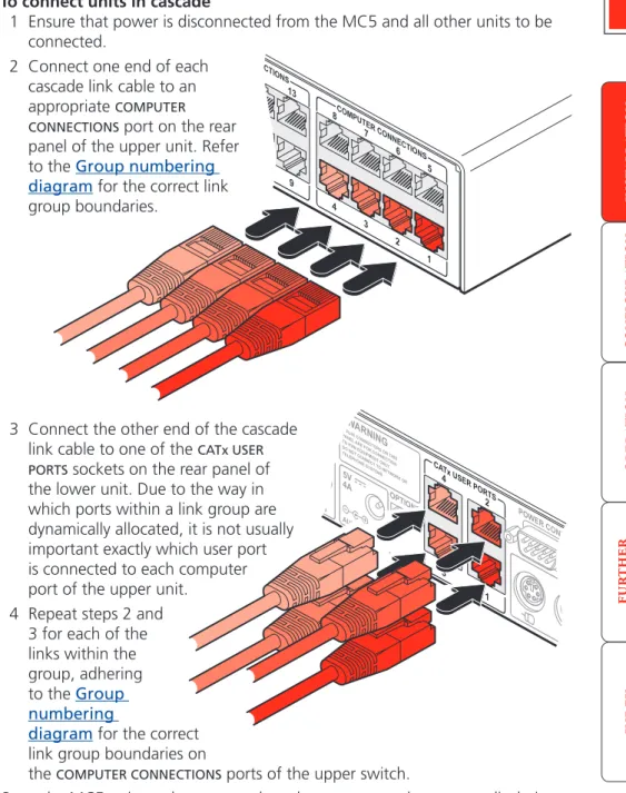
3 Connect the other end of the cascade link cable to one of the CATx USER PORTS sockets on the rear panel of
the lower unit. Due to the way in which ports within a link group are dynamically allocated, it is not usually important exactly which user port is connected to each computer port of the upper unit.
4 Repeat steps 2 and 3 for each of the links within the group, adhering to the Group numbering
diagram for the correct link group boundaries on
the COMPUTER CONNECTIONS ports of the upper switch.
Once the MC5 units and computers have been connected, you can edit their names to make it much easier to locate them. See the To create/edit computer names section in the Configuration chapter for more details.
Connecting MC5 units in cascade
Please consider the following when making cascade connections between MC5 units.
Tips for successful cascading
• The maximum number of levels for a cascade is three.
• The maximum number of computer systems that can be controlled within a cascade installation depends upon the MC5 unit placed at the top level. If the top level unit is a non-IP version, a maximum of 512 computer systems can be controlled. However, if the top level unit is an MC5-IP, the maximum number of computers drops to 128. This is due to the extra burden placed on the unit’s memory of administering global (IP) users.
• The number of links between units (three or four) determines the number of users that can simultaneously access the computers situated further down the tree. Link groups of one and two links should not be used.
• Ensure that cascade links (within a group) between units are approximately the same length.
• Triple and quad link groups may be mixed on one unit providing the links lie within the appropriate port boundaries designated in the Group numbering diagram.
• MC5-IP models can only be used at the top level of the cascade tree because they have only two CATx USER PORTS sockets and the minimum number of links required for a cascade group is three.
• For each cascade link, use a standard category 5, 5e or 6 twisted-pair cable, terminated at each end with an RJ45 connector. There must be no crossover connections within the cable, i.e. do not use patch cables. The cascade link cables can be up to 50m (160 feet) in length. However, remember that the overall length between any remote user (via a User Station) and any computer (via a CAM) must not exceed 300m (980 feet) - that figure includes the cascade link cables. Ensure that each of the links within a cascade group all conform to the same length.
• The procedure given opposite may be carried out in any order but for clarity the instruction will begin at the higher level MC5 unit (here called the upper unit), i.e. the one that is being fed into by a unit at the cascade level below (here called the lower unit). The procedure remains the same regardless of exactly which cascade levels are being connected. The basic rule is that each link is made by connecting a COMPUTER CONNECTIONS port of the upper
switch to a CATx USER PORTS of the lower switch.
To connect units in cascade
1 Ensure that power is disconnected from the MC5 and all other units to be connected.
2 Connect one end of each cascade link cable to an appropriate COMPUTER CONNECTIONS port on the rear panel of the upper unit. Refer to the Group numbering diagram for the correct link group boundaries. OPTIONS 1 3 2 4 5V WARNING ! RJ45 CONNEC TORSON THIS PANEL AR E FOR CO NNECTIO N TO KVM EQUIPM ENTONL Y. DONOT CONNECT TO NETW ORK OR TELEPHONE SYSTEM S 4A AUX PWR IN PWR IN POWER CONTRO L CATxUSER PORTS 12 3 ON See also
Using cascaded computers
In use, cascaded computers can be accessed using exactly the same methods as for those connected directly to the MC5. However, by far the easiest way is to use the on screen menu. This is because it displays the computer names and does not require any knowledge of port addresses, some of which (as discussed above) can be up to six digits long. See the Selecting cascaded computers
section in the Operation chapter for more details.
Testing specific links to cascaded computers
As mentioned previously, the best and most efficient way to access cascaded computers is by using the on screen menu and via non-specific routes through the link groups. However, during configuration or troubleshooting, it may be useful to test specific routes to computers in order to verify the various strands of each link group. By using specific port addresses for each unit, rather than link group numbers, you can precisely navigate a route through any part of the system.
To test a specific link
1 Simultaneously press and hold and .
Note: and are the standard hotkeys and can be altered to avoid
clashes with other devices or software. If you change the hotkeys, remember
to use the new ones in place of and when following these
instructions.
2 While still holding and , in sequence, press and release the full address of the required computer – remember to use specific port numbers, not link group addresses, e.g. 061802, not 424502.
21
OPTIONS 1 20 19 18 17 12 11 10 9 4 3 2 1 3 2 24 23 22 21 16 15 14 13 8 7 6 5 4 5V 5V WARNING !RJ45 CONNECTORS ON THIS PANEL ARE FOR CONNECTION TO ADDER KVM EQUIPMENT ONLY. DO NOT CONNECT TO NETWORK OR TELEPHONE SYSTEMS 4A 4A AUX PWR IN MAIN PWR IN ON1234POWER CONTROL COM1 / UPGRADE COM2 / MODEM
KM USER PORT 1
CATx USER PORTS COMPUTER CONNECTIONS COMPUTER CONNECTIONS COMPUTER CONNECTIONS Made in
the U.K.
Indoor use only
OPTIONS 1 20 19 18 17 12 11 10 9 4 3 2 1 3 2 24 23 22 21 16 15 14 13 8 7 6 5 4 5V 5V WARNING !RJ45 CONNECTORS ON THIS PANEL ARE FOR CONNECTION TO ADDER KVM EQUIPMENT ONLY. DO NOT CONNECT TO NETWORK OR TELEPHONE SYSTEMS 4A 4A AUX PWR IN MAIN PWR IN ON1234
POWER CONTROL COM1 / UPGRADE COM2 / MODEM
KM USER PORT 1
CATx USER PORTS COMPUTER CONNECTIONS COMPUTER CONNECTIONS COMPUTER CONNECTIONS Made in
the U.K.
Indoor use only
U S
U S
CAM
CAM
CAM
CAM
Slave MC5 Master MC5 Master monitor Slave monitor Computers fitted with dual video headsSerial synchronisation cable
Multiple video head connections
Two or more MC5 units can be connected together so that they operate in a synchronised manner. Synchronised operation is useful for applications that require multiple video signals to be switched together. This type of operation is usually required where each computer is fitted with multiple video cards or video cards with multiple video heads. Whenever an MC5 channel is switched, it sends an RS232 command out on its serial interface (marked
COM1/UPGRADE on the rear panel). An MC5 will switch its channel if it receives the same command on its serial interface. Consequently, by linking the serial interfaces, a master unit may be made to automatically switch one or more slave units as shown in the diagram.
It should be noted that the synchronisation cable deliberately does not have the transmit pin of the Slave End connector linked to the receive pin of the Master End connector. To do so would cause the Slave unit to be able to switch the Master unit. This would setup an endless cyclical switching sequence that would prevent the MC5 devices from operating correctly. For more details about the serial synchronisation cables, see Appendix 7.
REMOTE USER U S HOST COMPUTER CAM CAM REMOTE USER U S
The local user ports can also be used to view multiple video head installations.
Notes
It is recommended that the second CAM in each pair is a USB-type and that it is plugged to a vacant USB port on the host computer to derive its power. Pairs of CAMs can be strapped back-to-back with cable ties to create a tidy installation.
Configuration
Almost all configuration and operational aspects of the MC5 units are controlled via on-screen menu displays.
Overall initial configuration
When setting up a new installation, the following stages are recommended: 1 Enable the general ‘Security’ option.
With security disabled (default setting), all users attached to the MC5 have full and unrestricted access to all computers and all MC5 settings. In larger installations, you are strongly recommended to enable security and set up individual user accounts with access privileges.
2 Create an ADMIN (administration) password.
All MC5 units have a fixed user account that cannot be deleted, named ADMIN. This user account is the only one that is able to make important system changes. If you intend to use security, then it is important to allocate
a password to the ADMIN account.
3 Create user accounts and allocate access rights.
Use the ADMIN account to add user profiles, passwords and access rights for each of the system users.
4 Provide names for computers.
When numerous computers are attached, you are strongly advised to provide names for each, to assist with recognition.
5 Compensate video signals to account for link cable lengths
The long cable links that are possible between the MC5 unit and the computers and also to the remote users can affect the quality of the video images displayed. Use the in-built compensation features to eliminate any potential video image degradation.
6 Configure the required ‘Setup Options’ and ‘Global Preferences’
Use the ADMIN account to determine key MC5 settings and timing characteristics.
7 Configure the IP settings
MC5-IP models only. IP models possess a further collection of IP-related configuration options and encryption features that protect the installation from unauthorised global users - ensure that the IP security features are
23
LINDY MC5 Computer Port Computer 1 01 Computer 2 02 Computer 3 03 Computer 4 04 Computer 5 05 Computer 6 06 Computer 7 07 Computer 8 08User port 1 Status
ADMIN SHARED USE
F1-More menus F3-Find F2-Adj.Video F4-Logout
Configuration menus
The configuration menus allow you to determine many aspects of the MC5 capabilities. From here you can:
• Create individual user accounts and determine access rights,
• Provide names for all connected computers to allow quick recognition,
• Set individual and global settings for users,
• Run various functions, such as mouse restore operation,
• Save and load MC5 configuration settings, and more.
To access the configuration menu (local and remote users)
1 If the main menu is not already displayed, press and hold and then press using a keyboard attached to an MC5 user port.
The main menu will be displayed:
3 Use the and keys to highlight an option, then press to select.
LINDY MC5 Configuration Menu Functions Routing status User Preferences Global Preferences Setup Options Edit Computer List Edit User List Edit Autoscan List Enter-Select F1-More menus Esc-Quit
Firmware Version 1.02 Default names for
each computer port
Assistance for keypress options Your Login name
Connection status of this user port Identification of
this user port
Port numbers
2 Press To display the Configuration Menu:
Hotkeys
Note: and are the standard hotkeys and can be altered to
avoid clashes with other devices or software. If you change the hotkeys,
remember to use the new ones in place of and when following
the instructions in this guide.
Security
Note: If the security option has been enabled, you will be asked for a valid user name and password before the main menu can be displayed.
IMPORTANT: When supplied, MC5 units have their security features disabled, which means that any attached users have access to all connected computers and all MC5 settings. You are strongly recommended to enable the ‘Security’ feature and set an access password for the ADMIN account.
LINDY MC5
User Name: Password:
Port 1 login Esc-Scr Save
To access the configuration menu (global users)
Once the IP settings have been made (and the MC5-IP unit is network connected), global users can access the configuration menu using a different method.
1 Use either the VNC viewer or a standard web browser to make remote contact with the MC5-IP – see Global user access for more details.
2 If the username entry is not blanked out, enter ‘admin’ or another login username. Then enter the admin password (if no password is set, then just press ). Once logged in, the MC5-IP will show the video output from the host system (if one is connected), or otherwise a ‘No Signal’ message.
3 Click the ‘Controls’ button and select the ‘KVM Switch menu’ option. All options appropriate to the entered username will be displayed.
Configuration menus layout
The menu options are arranged as shown here:
For a description of each option within the Configuration menus, see
Appendix 1 for more details.
Configuration Menu Functions
(F1) Advanced Options User Preferences Routing status
Global Preferences
Setup Options
Edit Computer List Edit User List Edit Autoscan List
Restore Standard Mouse Restore Intellimouse Power Control Configure IP port Reset to Factory Defaults Send Data to RS232 port Read Data from RS232 port
DDC Options Power Control OSD Colour Reminder Banner Reminder Colour Screen Saver Type Confirmation Box Unit Configuration Network Configuration Modem Configuration Reset Configuration Mouse Switching Screen Saver Autoscan Mode Autoscan Period OSD Dwell Time User Timeout RS232 Mouse Type Mouse Type Security Language Hotkeys Keypad Controls Exclusive Use Automatic Logout
LINDY MC5-IP only
General security and configuration steps
To enable general security1 Display the Configuration menu. 2 Highlight ‘Setup Options’ and press .
3 Highlight ‘Security’ and press to select ‘ENABLED’. 4 Now create a new password for the ADMIN user account.
To set an ADMIN password
1 Display the Configuration menu. 2 Highlight ‘Edit User List’ and press .
3 Highlight ‘ADMIN’ and press . Press again to accept the name ‘ADMIN’ without change.
4 Enter an appropriate password for the ADMIN user account with regard to the following:
• The password can be up to 12 characters long. • The password can use letters, numerals and/or certain
punctuation marks.
• The password is not case sensitive.
5 Press . The ‘Edit Access Rights’ menu will be displayed. However, as the ADMIN account always has access to all computers, press again to save the new password.
What to do if the ADMIN password has been forgotten.
To change the hotkeys
MC5 units use and as their standard hotkeys. These can be changed if they clash with other software or hardware within the installation.
1 Display the Configuration menu. 2 Highlight ‘Setup Options’ and press .
3 Highlight ‘Hotkeys’ and press to select the required hotkey combination. The options are: CRTL+ALT, CTRL+SHIFT, ALT+SHIFT, ALT GR, LEFT ALT+RIGHT ALT, LEFT CTRL+LEFT ALT, RIGHT CTRL+RIGHT ALT or DISABLED.
25
Registering users (edit user list)
To create/edit user accounts1 Display the Configuration menu. Note: You must be logged-in as the ADMIN user.
2 Highlight ‘Edit User List’ and press .
5 Press to display the ‘Edit Access Rights’ menu.
LINDY MC5 Edit User List
admin Robert Oliver Johnny Sam Ins-Add Del-Delete F1-Clone Enter-Edit -Select Esc-Quit 3 Either:
• Create a new account - Press , enter a new user name and press ,
or
• Edit an existing account - Highlight the required user name and press
Edit the name, if appropriate, and/or press . 4 Enter or edit the password with regard to the following:
• The password can be up to 12 characters long.
• The password can use letters, numerals and/or certain punctuation marks.
• The password field can remain blank to allow open access to this account.
Here you can determine which of the connected computers can be accessed by the selected user account. Only computers that show the ‘+’ marker to the right of the menu box will be accessible to the user account.
Note: The Port Direct feature (which allows interconnected switching units
to talk to one another) ensures that users without access rights to particular computers cannot move sideways to those computers via other computers. Note: Access rights for user accounts to particular computers can also be controlled from the ‘Edit Computer List’ menu.
6 Select and deselect computers as follows:
• Individual computer - Highlight a computer name, then press to
apply, or remove, a ‘+’ marker. • Access to all computers – Press • Access to no computers – Press
7 When all settings have been made, press to save and exit. Press to return to the ‘Configuration Menu’.
LINDY MC5 Edit access rights
Computer 1 01 + Computer 2 02 + Computer 3 03 + Computer 4 04 Computer 5 05 Computer 6 06 + Computer 7 07 Computer 8 08 + Space-Toggle Enter-Save F1-All F2-None Esc-Quit F3-Find
Cross markers indicate which computers will be accessible to the currently selected user. To change the permission state: Highlight a computer and press the space bar.
Registering computers (edit computer list)
To create/edit computer entries1 Display the Configuration menu. Note: You must be logged-in as the ADMIN user.
2 Highlight ‘Edit Computer List’ and press . LINDY MC5
Edit access rights
admin Robert Oliver Johnny Sam + + + Space-Toggle Enter-Save F1-All F2-None Esc-Quit F3-Find LINDY MC5
Edit Computer List
Computer 1 01 Computer 2 02 Computer 3 03 Computer 4 04 Computer 5 05 Computer 6 06 Computer 7 20 Computer 8 414203 Ins-Add Del-Delete F1-Clone Enter-Edit -Select F3-Find Esc-Quit 3 Either:
• Create a new computer entry – Press and enter a new name, or
• Edit an existing computer entry – Highlight a computer name and press
. Press (Backspace) to delete existing characters and enter the required new name (up to 16 characters).
4 Press and the cursor will move to the computer port column on the right side. Change or enter the port address of the computer as required. See the
Addressing computers in a cascade section for more details.
5 When the port address is complete, press . The ‘Edit access rights’ menu will be displayed.
Here you can determine which users should have access to the created/ edited computer. Only users that show a ‘+’ marker to the right of the menu box will be granted access to the computer.
Note: The Port Direct feature (which allows interconnected switching units
to talk to one another) ensures that users without access rights to particular computers cannot move sideways to those computers via other computers. Note: Access rights for particular user accounts to computers can also be controlled from the ‘Edit User List’ menu
6 Select and deselect users as follows:
• Individual user - Highlight a user name, then press to apply, or
remove, the ‘+’ marker.
• Allow access for all users – Press
• Allow no user access (except ADMIN) – Press
6 When all settings have been made, press to save and exit. Press to return to the ‘Configuration Menu’.
Tips when creating/editing computer entries
• Avoid creating two names for the same computer port.
• When cascading to other units, do not apply individual names to any ports that are forming a link group to another switch (i.e. ports 1, 2, 3 & 4 when they form link group 41).
Cross markers indicate which uers will be granted access to the currently selected computer. To change the permission state: Highlight a user name and press the space bar.
27
Video compensation
The MC5 units allow computer systems to be placed up to 50m (160 feet) away and remote users to be extended by a maximum of 300m (980 feet). Such long cable lengths can affect video signals, especially when higher screen resolutions are used. In order to eliminate any video signal degradation, all MC5 units and accompanying User Station modules provide effective software-based video compensation features.
Two main types of video compensation are provided within the MC5 installation, these are:
• Computer video compensation - operates on video signals between each computer system and the MC5 unit. See Computer video compensation. • Remote user video compensation - operates on video signals between
each remote user(s) and the MC5 unit. See Remote user video compensation for details.
It is important to note that, providing the cabling arrangements do not change, the various video compensations need to be applied only once to each computer or remote user link. During operation, control of video compensation is fully automatic. Please take into account the following when configuring links:
• The MC5 stores a video compensation setting for each computer which defines the level of compensation that is applied whenever the computer is selected. This “computer video compensation” setting is to correct for any video clarity loss due to the CATx cable between the MC5 unit and the computer’s CAM.
• CATx cables below 10m give very little loss and so it is not normally
necessary to be concerned about setting any computer video compensation if short CATx cables are being used between the MC5 and the CAM for each computer.
• “Computer video compensation” may be setup by typing in the cable distance in the OSD or, if very fine video adjustment is desired, by observing the video picture on the local (user 1) port whilst making adjustments. • If a cascade of switches is being used, computer video compensation only
needs to be applied at the master MC5.
• “Remote user video compensation” compensates for any CATx cable losses introduced by the cable between the User Station and the MC5. The required video compensation setting does not vary as any “computer video compensation” is automatically added as different computers are selected. This only needs to be setup once during installation.
REMOTE USER
Overall maximum length between any remote user and any host system must not exceed 300 metres (980 feet) 300 metres (980 feet) maximum 50 metres (160 feet) maximum Computer video compensation Remote user video compensation U S CAM COMPUTER SYSTEM
Note: For installations where both computers and remote users require video compensation, always ensure that the computers are compensated first.
• A third type of video compensation is provided by User Station C5 Pro extender modules only. This type of compensation is called Skew adjustment and combats the effect of uneven twisted pairs within link cables.