Technical Best Practice White Paper
HP Data Center
Interconnect Deployment
Best Practice
HP 12500 Interoperating with Cisco Nexus 7000 over Optical
Connection
HP Data Center Interconnect Deployment Best Practice 2
Table of contents
Table of contents ... 2
Executive summary ... 3
Target audience ... 3
Data Center Interconnect overview ... 3
Data Center Interconnect design requirements ... 3
Spanning tree isolation ... 3
Layer 2 Data Center Interconnect link loop prevention ... 3
High availability ... 4
Path optimization and traffic suppression ... 4
MAC table aging timer synchronization ... 4
Multi-purpose/multi-application ... 4
Considerations of Cisco Nexus hardware limitations ... 4
Other limitations ... 5
DCI deployment options ... 5
DCI deployment guide for HP 12500 to Cisco Nexus 7000 over optical link ... 5
VLAN creation ... 6
802.1Q trunking ... 6
VRF/VPN-instance configuration ... 6
Layer 2 domain isolation and failure protection ... 7
VRRP and VRRP isolation ACL ... 7
Broadcast suppression ... 8
Jumbo Frame support ... 9
MAC table aging timer ... 9
iMC monitoring of DCI connections ... 10
iMC deployment of VLAN ... 13
Bill of Material ... 15
HW and SW version ... 15
Optical connectors ... 16
ANNEX ... 16
Executive summary
The purpose of this document is to provide the HPN SA/TC community with best practices in regards to deploying a HPN Data Center Interconnect (DCI) solution. This document is intended to cover a specific scenario involving 3rd party networking devices with direct fiber optical connections. This document is meant to cover Layer 2 and above networking environments.
The configuration within this document will provide the field with recommendations which are based on validations provided by the R&D test center. The configurations are only validated against specific SW versions.
It is strongly recommended that the HPN SA/TC community have a clear understanding of the customer requirements and risks before applying such configurations.
Target audience
This is a HPN internal doc designed for the HP SA, TC, and TME technical community. This document is intended to cover a Layer 2 and/or above networking environment.
Data Center Interconnect overview
The DCI solution provides enterprises with a higher level of reliability and IT agility, by enabling high availability, disaster recovery, and dynamic resource scheduling across geographically-dispersed data centers. The DCI solution is designed to provide Layer 2 networking connectivity between data centers over different WAN or MAN infrastructures, such as dark fiber, Dense Wavelength Division Multiplexing (DWDM), Multiprotocol Label Switching (MPLS), or IP backbones. To meet flexible customer requirements the DCI solution supports many varieties of platforms, from data center switches to routers, which can establish the Layer 2 connectivity. Customers can also leverage existing 3rd party hardware to
interoperate with the HPN devices when deploying the DCI solution.
The DCI solution is designed to enable applications like “vMotion” clustering which require Layer 2 networking adjacencies over geographically dispersed data centers. However, the DCI solution goes far beyond just connecting the 802.1Q trunks between the data centers.
This document focuses on how the HP 12500 switch interoperates with a Cisco Nexus 7000 to establish DCI connections over optical links. However, due to proprietary software implementations on the existing non-HP equipment, special arrangements must be made with regards to interoperating with the existing equipment.
Data Center Interconnect design requirements
Spanning tree isolation
The DCI solution is meant to provide Layer 2 networking connectivity across geographically dispersed data centers; however, we must separate the Spanning Tree domains from each data center so that Spanning Tree Protocol (STP) convergence at one site will not affect the rest of the network.
Layer 2 Data Center Interconnect link loop prevention
When DCI links are introduced to the data center network it is critical that another loop is not created via the deployment of DCI links, especially when there is more than one physical link involved. In the optical
connection environment, when multiple connections exist, a Link Aggregation Control Policy (LACP) group is recommended to provide full bandwidth utilization and load balancing. In a MPLS/ Virtual Private LAN Service (VPLS) type of environment, active/standby links are recommended to eliminate the loop.
High availability
High availability is very critical to a data center network design. With the DCI link interconnecting the data centers, it is critical to have redundancy on both the control plane and the data plane. HPN IRF
technology can protect the control and data plane by providing millisecond level failover protection and ISSU capability.
Path optimization and traffic suppression
By interconnecting the data centers over a Layer 2 network, it also brings up the concern of optimizing the path to and from the gateway. To minimize the traffic going across the DCI link and to optimize the path, active Layer 3 gateways are recommended in each data center to avoid trombone routing.
Standard protocols such as Virtual Router Redundancy Protocol (VRRP) are recommended to provide this function as gateway in each data center. VRRP isolation Access Control Lists (ACLs) can be used to ensure that the VRRP traffic, such as “keep-a-lives”, remains local to each data center. Isolating the VRRP traffic at each data center minimizes unnecessary traffic over the DCI link and avoids causing confusions for the other data center.
Certain commands can also be used to limit the unnecessary broadcast traffic as an optional measurement to control the broadcast on the DCI link for specific applications.
MAC table aging timer synchronization
With multiple data centers interconnected over a Layer 2 network, it is critical to ensure that the MAC address table has the same aging timeout settings. This is to ensure the MAC address table in the local data center is consistent with the remote data center, so that when a local switch forwards the Ethernet frame to the remote data center, the remote switch has an up to date MAC address table for the final destination. This is even more critical when equipment from different vendors interoperate across different data centers as they will have different default setting for flushing the MAC address table.
Multi-purpose/multi-application
To better utilize the DCI link and to lower the Total Cost of Ownership (TCO), the DCI link could be shared across multiple groups or applications. By separating each application with different VLAN and Virtual Route Forwarding (VRF), the specific traffic flow can be isolated from the rest of the background traffic and secured from non-VRF traffic.
Considerations of Cisco Nexus hardware limitations
Based on public Cisco documentation, certain limitations applies on the Nexus 7000 platform.With the lack of an out bound MAC ACL, traffic suppression e.g. VRRP keep alive filtering on each VLAN, would require special arrangement on the Nexus 7000. The workaround is to create another Virtual
Device Context (VDC) on the Nexus 7000, and use in bound ACLs to filter any un-necessary traffic from VRRP before reaching the DCI link.
“Guidelines and Limitations for MAC ACLs” - Cisco
MAC ACLs have the following configuration guidelines and limitations: • MAC ACLs apply to ingress traffic only
http://www.cisco.com/en/US/docs/switches/datacenter/sw/6_x/nx-
os/security/configuration/guide/b_Cisco_Nexus_7000_NX-OS_Security_Configuration_Guide__Release_6.x_chapter_01111.html
Other limitations
It is strongly recommended to use standard protocols for First Hop Redundancy Protocol (FHRP). Cisco proprietary protocols such as Hot Standby Router Protocol (HSRP) are not supported for the DCI solution. The DCI solution does not support the interoperability with Cisco proprietary HSRP, as the Cisco Nexus 7000 cannot filter outbound Generic Attribute Registration Protocol (GARP) sent by their gateway with the physical Mac address, which confuses the rest of the hosts on each VLAN interconnected over DCI link. Only an industry standard protocol such as VRRP is supported to achieve active/active gateway across the data centers.
DCI deployment options
The DCI solution leverages standard based technology to offer different options for interconnecting the data centers, based on customer demands and existing environments. DCI solutions can be designed to leverage optical links (DWDM), MPLS/VPLS and IP to enable the Layer 2 extensions. Additionally, DCI solutions are capable of supporting point to point topology to fully meshed multi data center topologies. There are also a wide selection of HPN router and switch platforms which support the DCI solutions, from HP 8800 routers to 7500, 9500 and 12500 switches. DCI as a standard based solution can even support 3rd party equipment which interoperates with HPN platforms for the best interest of a customer’s
investment protection.
The following section focuses on how to establish an DCI link across optical connections between HPN 12500 switches running IRF and a Nexus 7000.
DCI deployment guide for HP 12500 to Cisco Nexus 7000 over
optical link
The following deployment guide is based on the validation tests completed between HP 12500 switches and a Cisco Nexus 7000 connected over an optical fiber connection. A detailed deployment guide on how to establish the DCI is provided on both HPN equipment and Cisco Nexus platforms.
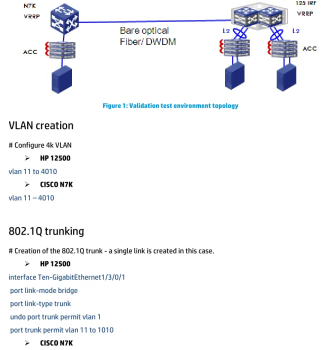
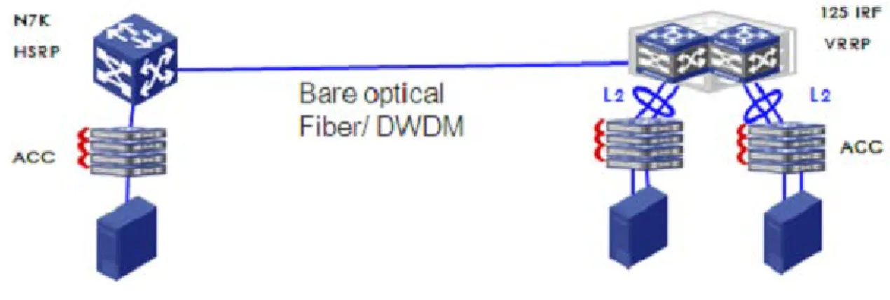
The following topology shows the validation test environment. During the validation test, only one 10GbE connection is created between the HP 12500 and Cisco Nexus 7000. There are two HP 12500 switches running in IRF mode to provide the customer with the best High Availability (HA) and failure protection. Only one Cisco Nexus 7000 is used on the other side due to no such multi-chassis technology and the lack of availability of the equipment.
The validation is done based on the specific topology, hardware and software as listed in the bill of materials. The hardware and software configurations are subject to change by their vendor from
time to time without notice. The recommendations are considered as reference only. Exact customer requirements and risks must be understood before deploying such configuration.
Figure 1: Validation test environment topology
VLAN creation
# Configure 4k VLAN
HP 12500
vlan 11 to 4010
CISCO N7K
vlan 11 – 4010
802.1Q trunking
# Creation of the 802.1Q trunk - a single link is created in this case.
HP 12500
interface Ten-GigabitEthernet1/3/0/1 port link-mode bridge
port link-type trunk
undo port trunk permit vlan 1 port trunk permit vlan 11 to 1010
CISCO N7K
interface Ethernet3/18 switchport
switchport mode trunk
switchport trunk allowed vlan 11-1010
VRF/VPN-instance configuration
# Creation of the VPN VRF and attaching the VRF to individual VLAN interface. This is to protect the traffic from each different VLAN and application from being mixed together.
HP 12500
route-distinguisher 1:1
vpn-target 1:1 export-extcommunity
vpn-target 1:1 import-extcommunity interface Vlan-interface11
ip binding vpn-instance vpn1
CISCO N7K
vrf context vpn1
address-family ipv4 unicast interface Vlan11
vrf member vpn1
All L3 configs on interface VLAN will be deleted, so you must re-configure the IP address of the interface after configuring the command.
Layer 2 domain isolation and failure protection
# Limit the STP domain within each data center to isolate failure domains in peer data center. Different data centers could use different STP protocols. This can be used to separate MST and PVST operation.
HP 12500
interface Ten-GigabitEthernet1/3/0/1 stp disable
CISCO N7K
interface Ethernet3/18
spanning-tree bpduguard enable spanning-tree bpdufilter enable
VRRP and VRRP isolation ACL
To provide routing path optimization, it is recommended to enable both sides of the DCI link with active Layer 3 gateways leveraging VRRP to hide the specific HW details. Both data centers will run separate sets of VRRP instances. VRRP isolation ACLs will stop the population of VRRP keep-a-lives over the DCI link, so that the peer data center will always maintain master status. This could be applied to
applications that require a symmetrical routing path.
Create the interface gateway for servers, and define the same VRRP VIP on both sides of the DCI. Apply VRRP isolation at the outbound direction of the 12500 and deploy the VACL on the N7K device. VACL on the N7K device will only work at an inbound direction, so it can’t stop VRRP packets from being sent to the 12500. A separate Nexus VDC must be created, apart from the one that acts as the gateway. The new VDC will be used to provide a MAC layer ACL from the inbound direction when connected with the VRRP gateway VDC. Apply VACL on the new N7K VDC that is trunked between Layer 3 gateway and DCI link, as N7K VACL only works at “inbound” direction.
HP 12500
interface Vlan-interface11
ip address 11.1.1.2 255.255.255.0 vrrp vrid 1 virtual-ip 11.1.1.1
acl ipv6 enable
Applied Packet filter at the port of the 12500, make sure that you have set “ACL ipv6 enable” in system view. Otherwise the ACL of the packet filter can’t be set into the memory of the chip and it will not work. It will take effect after a system restart.
acl number 4001 description DENY VRRP
rule 0 deny type 0800 ffff dest-mac 0100-5e00-0012 ffff-ffff-ffff rule 100 permit
# Deploy the packet filter on the interface of the device at the outbound direction. interface Ten-GigabitEthernet1/3/0/1
port link-mode bridge packet-filter 4001 outbound
CISCO N7K
# First, enable feature before configuring interface-vlan and vrrp. feature interface-vlan
feature vrrp interface Vlan11 no shutdown
ip address 11.1.1.3/24 vrrp 1
address 11.1.1.1 no shutdown
# Create new VDC on N7K. The new VDC will be trunking Layer 3 GW VDC and terminating the DCI link. Define access-list , rule 10 to isolate VRRP hello packet, avoid VRRP roles selecting.
ip access-list vrrp statistics per-entry
10 permit ip any 224.0.0.18/32
# Deploy the VACL on N7K, it works at inbound direction. vlan access-map vrrpfilter 10
match ip address vrrp
action drop vlan filter vrrpfilter vlan-list 11-1010
2 extra interfaces of N7K for trunks between VDCs
Broadcast suppression
# This is an optional measurement to suppress the broadcast if specific applications emits broadcasts overwhelmingly. Refer to the command reference for further details. Adjust the percentage of the suppression to the individual scenario.
HP 12500
broadcast-suppression pps 64000
Use the broadcast-suppression command to set the broadcast suppression threshold on an Ethernet interface. Specifies the maximum number of broadcast packets that the Ethernet interface can receive per second.
CISCO N7K
interface Ethernet3/18
storm-control broadcast level 10.00
The broadcast traffic suppression level for an interface as a percentage of total bandwidth. The level can be from 1 to 100. The optional fraction of a level can be from 0 to 99. A threshold value of 100 percent means that no limit is placed on broadcast traffic. A value of 0.0 means that all broadcast traffic on that port is blocked.
Jumbo Frame support
# Certain applications may require jumbo frame support, such as vMotion. Adjust the MTU of the interfaces to ensure the transmit of large packets.
HP 12500
[125-1-Ten-GigabitEthernet1/3/0/1]jumboframe ? Enable jumboframe enable
# The default Maximum Frame Length is 9216. [125-1-Vlan-interface11]mtu ?
INTEGER<64-9198> MTU value
# The default Maximum Transmit Unit is 1500.
CISCO N7K
switch-solution(config)# interface ethernet 3/18 switch-solution(config-if)# mtu ?
<1500-9216> Enter MTU # The default MTU is 1500.
switch-solution(config)# interface vlan 13 switch-solution(config-if)# mtu ?
<64-9216> MTU size in bytes
MAC table aging timer
# It is strongly recommended to sync up the MAC table aging timer from both sides of the data center. This will ensure Layer 2 network connectivity across the data centers, and this will also reduce the amount of ARP and broadcast over the DCI link and ensure no Layer 2 traffic loss. The longer the aging timer is, the less ARP requests being sent across all the data centers.
HP 12500
mac-address timer aging ?
INTEGER<10-3600> Global aging time (second) The default timer is 300s.
mac address-table aging-time ? <0-0> 0 disables aging
<120-918000> Aging time in seconds. The default aging time is1800s.
iMC monitoring of DCI connections
# In the case of 3rd party switches being involved, only standard MIBs from non-HPN equipment are
supported.
SNMP configuration
# First, configure SNMP parameters.
HP 12500
snmp-agent
snmp-agent local-engineid 800063A203002389515001 snmp-agent community read public
snmp-agent community write private snmp-agent sys-info version all snmp-agent group v3 group
snmp-agent target-host trap address udp-domain 192.168.100.200 params security ame public snmp-agent trap source M-Ethernet1/0/0/0
CISCO N7K
snmp-server source-interface trap Ethernet3/18
snmp-server user admin vdc-admin auth md5 0x24b81025eaad4324221599e728714cfa priv 0x24b81025eaad4324221599e728714cfa localizedkey
snmp-server host 192.168.100.200 traps version 1 public snmp-server enable traps callhome event-notify
snmp-server enable traps callhome smtp-send-fail snmp-server enable traps cfs state-change-notif snmp-server enable traps cfs merge-failure snmp-server enable traps aaa server-state-change
snmp-server enable traps feature-control FeatureOpStatusChange snmp-server enable traps sysmgr cseFailSwCoreNotifyExtended snmp-server enable traps config ccmCLIRunningConfigChanged snmp-server enable traps snmp authentication
snmp-server enable traps link cisco-xcvr-mon-status-chg snmp-server enable traps vtp notifs
snmp-server enable traps vtp vlancreate snmp-server enable traps vtp vlandelete snmp-server enable traps bridge newroot
snmp-server enable traps bridge topologychange snmp-server enable traps stpx inconsistency snmp-server enable traps stpx root-inconsistency snmp-server enable traps stpx loop-inconsistency snmp-server community public group vdc-operator snmp-server community private group vdc-admin
LLDP configuration
# Cisco device has limitations of MIBs, it does not support BasePort. So iMC cannot show the interconnection link by mac address, so it shows the link by LLDP.
HP 12500
Lldp enable
CISCO N7K
# Enable feature LLDP. feature lldp
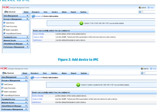
Add device to iMC
Figure 2: Add device to iMC
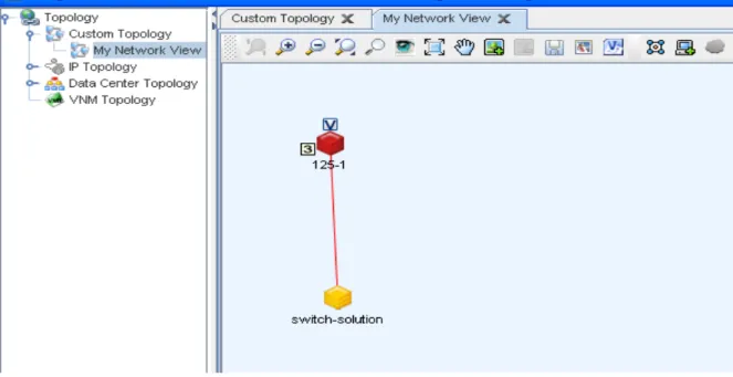
Topology – linkup
Figure 4: Linkup topology
Topology –“link down”
When the status of a link changes, right click the mouse and select “reload” to refresh the status of the link.
Figure 6: Link down topology
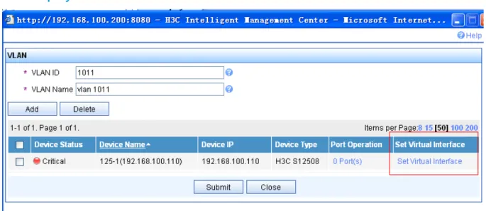
iMC deployment of VLAN
Figure 7: VLAN deployment task
VLAN deployment task list
Figure 8: VLAN deployment task list
Figure 9: Set VLAN virtual interface
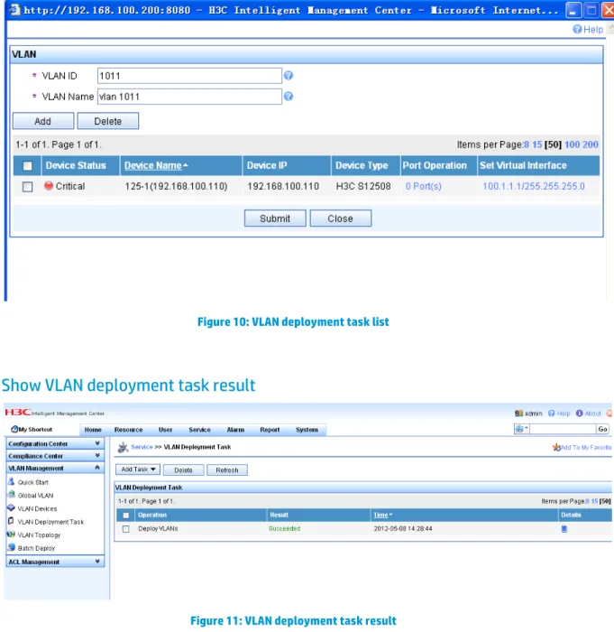
Show VLAN deployment task list
Figure 10: VLAN deployment task list
Show VLAN deployment task result
Figure 11: VLAN deployment task result
Bill of Material
HW and SW version
12500
Comware Software, Version 5.20, Release 1728P01
Comware Platform Software Version COMWAREV500R002B101D007SP02 H3C S12508 Software Version V100R007B01D007SP05
Nexus 7000
Software
BIOS: version 3.22.0 kickstart: version 6.0(1) system: version 6.0(1) Hardware
cisco Nexus7000 C7010 (10 Slot) Chassis ("Supervisor module-1X") Intel(R) Xeon(R) CPU with 4104304 kB of memory.
Device name: switch-solution bootflash: 2029608 kB
slot0: 0 kB (expansion flash) Table 1: HW and SW versions
Optical connectors
HP 12500
Here we used HP X130 10G XFP LC LR Transceiver (JD108B) (H3C’s XFP-LX-SM1310) in the 12500, if we use a non HP/H3C’s fiber module our device will keep on print log on the command view to info the event.
CISCO N7K
Here we use HP X130 10G XFP LC LR Transceiver (JD108B) (H3C’s XFP-LX-SM1310) fiber module in the N7K and use this command to cancel the limits of the fiber modular’s type.
service unsupported-transceiver
ANNEX
As shown in this figure, if the Cisco N7K deploys HSRP while the HP 12500 deploys VRRP, we can see that the N7K uses the real mac to send gratuitous ARP and ARP requests. We cannot filter the gratuitous ARP packets and let ARP request packets pass to the server connected to the 12500. If we don’t filter them, the clients will change the mac address of the gateway while receiving the gratuitous ARP from the N7K. If we filter them, the server connected to the 12500 can’t communicate with the server connected to the N7K at layer 3.
Figure 12: HSRP & VRRP topology diagram 1
The following diagram shows the captured ARP packets of the N7K and the HP 12500.
Figure 13: Gratuitous ARP of N7K diagram 2
For more information
To read more about HP solutions, go to http://www.hp.com/networking.
Get connected
hp.com/go/getconnected
Current HP driver, support, and security alerts delivered directly to your desktop
© Copyright 2012 Hewlett-Packard Development Company, L.P. The information contained herein is subject to change without notice. The only warranties for HP products and services are set forth in the express warranty statements accompanying such products and services. Nothing herein should be construed as constituting an additional warranty. HP shall not be liable for technical or editorial errors or omissions contained herein.
Created July 2012 Updated August 2012