ISSN 2457-0931
Imperial International Journal of Eco-Friendly Technologies (IIJET)
Vol.3, Issue – 1 (2018), pp. 28-32
Rear Wheel Steering for a Tadpole Design
Controlling rear wheel while parking
TEAM AGNEYA, SHIV NADAR UNIVERSITY
Rakesh Rayapureddi
Alluri Jairam, VaibhavSehgal
Mechanical Mechanical MechanicalShiv Nadar University, Shiv Nadar University Shiv Nadar University, Greater Noida, India Greater Noida. India Greater Noida, India
Abstract-
Due to toxic emissions from the IC engine vehicles, there is a big drift towards Electric Vehicles recently. Even in electric vehicles, we face a limitation when it comes to charging the battery. In order to overcome that, solar energy (a renewable resource) is used in this project to charge the battery. It is driven by a 48V 1500W in-wheel hub motor supported by a 48V 74Ah battery. The solar-driven vehicle undergoes reverse motion when the polarity of the motor is reversed. In order to achieve sharp maneuvering which is a necessity for accurate parking of the vehicle, the vehicle is equipped with a rear wheel steering system which is based on the boat rudder steering mechanism. Two interconnected three link mechanism is used to fulfill this purpose which has been described in this paper. The paper finally concludes by showing how all of this is achieved in a cost-effective manner.
Keywords- parallel parking, short turning radius, rear wheel steering, three-wheel vehicle
I.
INTRODUCTION
Nowadays, the condition of increasing road traffic
makes the handling of vehicles more difficult. The present scenario demands an exploration of new vehicle handling mechanism, which inspired us to find out an alternative way. While the vehicles enter a congested or a narrow area, there is less space for turning the vehicles, therefore, it is desirable to have a small turning radius forthe vehicle or a mechanism through which they could move the wheel sideways without turning the vehicle.The major applications of Steering at both the rear as well as the front wheels are thatwith the help of this system, we can turn the rear wheel as well as the front wheel, whenever required according to our
preferences and the requirement of the environment around on the road. Thus, the vehicle can be controlled more effectively especially during parking or turning on a small radius. When both the front and rear wheels steer toward the same direction, they are said to be in-phase. When the front and rear wheels are steered in the opposite direction, this is called anti-phase.
Figure 1: Wooden Boat Rudder.
Our project concentrates on the advancement in the steering system of an automobile with the objective to reduce the turning radius considerably thereby reducing the space required to turn, and provide a sideways movement for easier parking and to reduce driver’s effort and time consumed to park the vehicles properly or perform a U-Turn.
II.
IDENTIFICATION OF PROBLEM
The current steering mechanism using rack and pinion currently focuses only on the arrangement to turn two wheels together and fails to turn a single wheel. In order to turn a vehicle with a short turning radius, we have to perform multiple steps by changing the gear from reserve to front and vice
ISSN 2457-0931
Imperial International Journal of Eco-Friendly Technologies (IIJET)
Vol.3, Issue – 1 (2018), pp. 28-32
versa, this is a time-consuming process using frontwheel steering. This is due to unavailability of steering control at the rear end.
With the increasing number of vehicles on the road, it has become more difficult for drivers to park the vehicles in confined parking spaces. It becomes an impossible task for a single driver sometimes to park properly in a confined space without the assistance of a second person outside the vehicle and guiding him the proper direction to turn and to prevent any damage to the vehicle, this also consumes a lot of valuable time of the user. Hence there’s a need for some new mode for steering.
III. PROPOSED METHODOLOGY
Vehicles with a four-wheel steer or such an advance mechanism are costly, hence we have finally come up with an idea of turning the rear wheel at the minimal cost possible. With more savings on purchasing the vehicle and on purchasing overpriced fuel every time and more time in hand to do other errands then spending time on parking or turning your vehicle, human life can be made comfortable.
The presented methodology is implemented in Tadpole Designed Electric-Solar Powered Vehicle using In-wheel Hub motor as the driving source at the rear wheel and can be retrofitted in low weight automobiles also.
Figure 2: Assembly of rear wheel steer mechanism.
Fig 2 shows the assembly of the proposed model for controlling the back wheel at low speeds mostly during parking, which is explained clearly in later discussion.
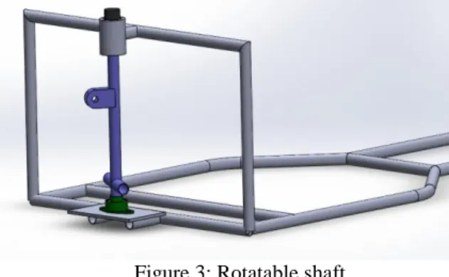
Figure 3: Rotatable shaft.
The movable shaft is attached to the chassis with the bearing at the bottom part and coupled with a motor at the top using key and slot, as shown in Fig 3. The Motor in the figure is portrayed by the Dark Cap at the top of the shaft in Fig 4.The rear wheel of the vehicle which consists motor that is attached with a mono-shock swingarm or H-arm with a bush joint and connected to the movable shaft. The movable shaft is controlled electronically with the help of a motor connected at the topmost point of the movable shaft and with the help of a bearing at the bottom-most part.
Figure 4: In-wheel hub motor attached to the swing arm. With the bearing at the base, it is easy to rotate the Rear Wheel along with the Monoshock Swing Arm Suspension system.
ISSN 2457-0931
Imperial International Journal of Eco-Friendly Technologies (IIJET)
Vol.3, Issue – 1 (2018), pp. 28-32
Figure 5: Movable shaft with bearings and motor.
IV .MOTOR TORQUE CALCULATIONS
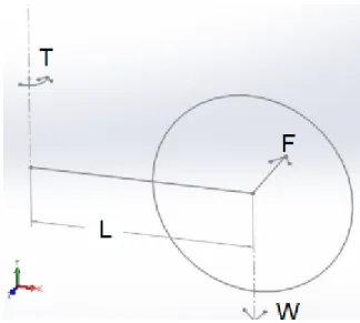
From Fig 6, The torque required at the motor mount shaft is:
Torque, T = Axial force x L Where, Axial Force, F = Force required to push and pull the rear wheel in sidewise direction for turning. L = Length of swing arm= 20”= 0.508 m Frictional Force,
F = ℳ x N
Where, ℳ= Kinetic Coefficient of Friction
N= Normal reaction of wheel= M x g
Where, M= Unsprung Mass in kgs,g = 9.81
𝑚𝑠−2N = M x g
= 9.81 x 10 Newtons = 98.1 Newtons
F = 0.7 x N Newtons = 68.67 Newtons
Therefore, the torque required; T = F x L
= 34.8843 Nm.
Therefore, a motor of torque 35 Nm is selected as an auxiliary motor to control the shaft to which the swingarm is attached.
Figure 6: Block Diagram of Rear Wheel.
Working Principle
In Boat, we turn the rudder to change the direction of the boat with the help of fluid dynamics as shown in Fig 7. Taking inspiration from it we made a mechanism similar to it where our whole Rear wheel rotates along a single shaft just like the rudder in a boat. This allows easy steering of the Rear Wheel without compromising the rear Suspension.
Figure 7: Boat Steering Mechanism.
The Shaft is rotated using the auxiliary motor within a certain range of angles
(−25∘𝑡𝑜 25∘) which is attached to the chassis and coupled to the shaft. Using the Motor we can control the angle at which we want to steer the rear wheel precisely. With the help of Raspberry Pi and relay, we can control the Motor electrically using a controller (Fig 9), which makes steering easy.
ISSN 2457-0931
Imperial International Journal of Eco-Friendly Technologies (IIJET)
Vol.3, Issue – 1 (2018), pp. 28-32
Figure 8: Controller Circuit
In order to prevent bump steer or accidental steer of the Rear wheel in normal driving conditions, we have implemented a lock mechanism with the help of a key through which we prevent the shaft from rotating on its axis. This will restrict the movement of the Rear wheel under normal drive conditions preventing any miss happening. As shown in Fig 9. The key is detachable and can be easily removed
Fig 9: Lock for the rear wheel
It is hard to turn the steering wheel under the resting conditions. Hence, when in the dynamic state it gets easier to turn the vehicle as there is a less opposing force acting on the tires. Similarly, The load on the Motor will be maximum when on full load and resting condition. But when the vehicle is in motion, the load on the Motor will reduce and it could steer the rear wheel easily and consume less energy. Considering the stability of the three wheels vehicles, we didn’t alter any property of the Rear Suspension. As in a Tadpole Design, the Rear Wheel plays an important part in the stability, therefore compromising the Rear Wheel would mean compromising the whole vehicle. Hence, in order to prevent slip during the turning of the rear wheel, we have provided Monoshock swing arm suspension with three linkage rocker mechanism. This was taken
into consideration when the research graduates were working with an electric Scooter with In-Wheel Hub motor in the rear and they found the problem of slipping of the rear wheel there. Therefore, taking their practical knowledge into account, we decided to use the three link rocker mechanism which is also used in many bikes these days.
Fig 10: Suzuki GSXR 1000 Suspension Linkage
RESULT AND DISCUSSION
There is various type of steering mechanisms
which are used for four wheeler vehicles. Hence,
here we discussed another steering mechanism
that can be used for the rear wheel for a
three-wheel tadpole design vehicle. The working of
this mechanism has been studied and showed in
detail. This mechanism has certain advantages
over other steering mechanisms since it is easier
to operate and cost-effective. Rear wheel
steering makes it easier for the driver to turn the
vehicle at a smaller radius and park it properly in
confined spaces. The project has been designed
to perform the entire requirement task safely and
precisely, which has also been satisfied.
ISSN 2457-0931
Imperial International Journal of Eco-Friendly Technologies (IIJET)
Vol.3, Issue – 1 (2018), pp. 28-32
(b)
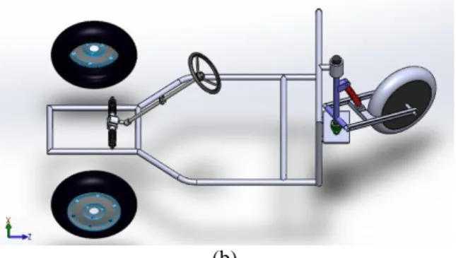
Fig
11: (a) and (b) shows both the steering mechanismThe project has been made to reduce the effective cost of the vehicles on road by the introduction of Three Wheel Vehicles which occupy less space in the day to day life and less power to operate. In addition to that, the vehicle is an Electric vehicle which is powered by Solar Energy. Hence, it is cost effective and provides all the luxuries of an expensive car with no extra expenditures on Petroleum Fuel with zero carbon emission. With proper use of the Rear steer, one can reduce the time taken in parking and turning to a substantial amount.
CONCLUSION
This article proposed a steering mechanism that precisely satisfies the needs of rear steer design in a Tadpole Vehicle. After pointing out the stability problems that we may face with the three-wheel vehicle design and then finding a way to prevent it with the three linkage mechanism, we didn’t compromise with the stability. In addition to that, a lock is attached with the movable shaft to keep the rear wheel intact while normal drive and can be unlocked automatically when the vehicle to be reversed.
We make this project entirely different from other projects. Since the concepts involved in our project is entirely different from that of an ordinary vehicle.
REFERENCES
[1] Chatterjee, M, Kale, M ., & Chaudhari, B. (2015). Mathematical modeling of chassis dynamics of electric narrow tilting three-wheeled vehicle. 2015 Annual IEEE India Conference (INDICON). doi:10.1109/indicon.2015.7443585 [2] Mg, V., 1, & Alam, S., 2. (2018). Steering
Report. Four Wheel Steering System.
[3] Author Low Mileage, YouTube. (2018). - GSXR 1000 Powered Spartan Trike Build