Basler Electric’s Digital Genset Controller (DGC-2020) is a highly advanced integrated genset control system. The DGC-2020 is perfectly focused, combining rugged construction and microprocessor technology to offer a product that will hold up to almost any environment and flexible enough to meet your application’s needs. This device provides genset control, transfer switch control, metering, protection and programmable logic in a simple, easy to use, reliable, rugged, and cost effective package. Program the DGC-2020 with easy to use front panel navigation keys and the large LCD display or with our enhanced BESTCOMSPlus PC software. Either way, the easy to follow menus make setup and configuration fast and simple. Within BESTCOMSPlus, we have provided a very powerful user-friendly programmable logic program that allows the user to meet specifications that previously would have required an additional PLC to meet. BESTCOMSPlus is included at no additional cost and provides for remote communications, file transfer, and file management. It is one of the most intuitive software programs available for genset controllers.
• Generator Metering • Engine Metering • Genset Control • Engine Protection
• Generator Protection (27, 59, 81O, 81U)
• BESTCOMSPlus (included with every DGC-2020 at no additional cost) - Programming and setup software - Intuitive and powerful - Remote control and monitoring - Programmable Logic - USB communications
• Automatic Transfer Switch Control • Automatic Synchronizer (optional) • Suitable for use on rental gensets with
- Hi/Lo line sensing - Single or three phase sensing override • SAE J1939 Engine ECU communications
• Multilingual capability
• Remote communications to our RDP-110 Remote Annunciator • Extremely rugged, fully encapsulated design
• 16 programmable contact inputs
• 7 Contact outputs: (3) 30 Adc and (4) Programmable 2 Adc rated contacts • Wide Ambient Temperature range
• Additional (8) Programmable 2 Adc contacts (optional)
• Remote Dial-out and Dial-in capability with Internal Modem (optional) • Enhanced Generator Protection 51 and 47 available (optional) • Modbus Communications with RS-485 (optional)
• Expandable I/O capabiity via J1939 CANBUS (optional) • UL recognized, CSA certified, CE approved
• HALT (Highly Accelerated Life Tests) tested • IP 54 Front Panel rating with integrated gasket • NFPA110 Level Compatible
FEATURES
DGC-2020
DIGITAL GENSET
CONTROLLER
DESCRIPTION,
FUNCTIONS and
SPECIFICATIONS
pages 2 through 5
FRONT PANEL DISPLAY
and
DIMENSIONS
pages 5 and 6
INTERCONNECT
DRAWING
page 7
ORDERING
INFORMATION
page 8
ROUTE 143, BOX 269 HIGHLAND, ILLINOIS 62249, U.S.A. PHONE 618-654-2341 FAX 618-654-2351
ADDITIONAL INFORMATION
INSTRUCTION MANUAL
The DGC-2020 is a microprocessor based generator set controller that incorporates advanced technology and features into a value added, user friendly, rugged design. This device is encapsulated and is the most rugged genset controller found anywhere. It provides front panel and PC programmability. It can sense engine parameters directly via analog senders, or it can communicate with the engine's ECU using SAE J1939 CANBUS communications. This device offers programmable inputs and outputs and programmable logic to allow the user to easily customize the operation of the DGC-2020 as desired. The DGC-2020 also has automatic transfer switch control (mains failure).
The DGC-2020 can be configured by a customer selected style number. This allows the user to only purchase what is needed, adding to the value of the DGC-2020 controller. The DGC-2020 can be configured to have eight additional output contacts, an internal RS-485, an internal industrial modem for remote communications and dialing out to a pager when the DGC-2020 detects trouble. The DGC-2020 also has optional features for enhanced generator protection, and an integrated automatic synchronizer.
DESCRIPTION
FUNCTIONS
GENSET PROTECTION
Generator (Standard Protection) Enhanced Generator Protection (Optional)
Undervoltage (27) Underfrequency (81U) Phase Imbalance (47) Overvoltage (59) Overfrequency (81O) Generator Overcurrent (51) All Generator Protection features are programmable as Alarms or Pre-alarms.
Engine
Alarms (Shutdowns) Pre-Alarms (Warnings)
Low Oil Pressure Low Oil Pressure Engine kW Overload
High Coolant Temperature High Coolant Temperature Maintenance Interval Timer Low Coolant Level Low Coolant Temperature Low Coolant Level
Overspeed Battery Overvoltage High Fuel Level
Overcrank Weak Battery Low Fuel Level
Engine Sender Unit Failure Battery Charger Failure Fuel Leak Detect Fuel Leak/Fuel Sender Failure Engine Sender Unit Failure
Emergency Stop Battery Charger Failure
All Alarms and Pre-Alarms can be enabled or disabled via the BESTCOMSPlus PC software or the front panel.
GENSET METERING
• Metered generator parameters include voltage, current, Hz, real power (watts), apparent power (VA), and power factor. • Metered engine parameters include oil pressure, coolant temperature, RPM, battery voltage, fuel level, engine runtime, and various J1939 supported parameters.
ENGINE CONTROL
Cranking Control: Cycle or Continuous (Fully Programmable)
Engine Cooldown: Smart Cooldown function saves fuel and engine life. Successful Start Counter: Counts and records successful engine starts Timers:
• Engine Cooldown Timer • Arming Time Delays after Crank Disconnect:
• Engine Maintenance Timer - Low Oil Pressure
• Pre-Alarm Time Delays for Weak/Low Battery Voltage - High Coolant Temperature
• Alarm Time Delay for Overspeed • Pre-Crank Delay
• Alarm Time Delay for Sender Failure • Continuous or Cycle Cranking Time Delay
EVENT RECORDING
The DGC has an event recorder that provides a record of alarms, pre-alarms, engine starts, engine runtime loaded, engine runtime unloaded, last run date, and many other events that are all date and time stamped to help the user determine the cause and effect of issues related to the generator set.
TRANSFER SWITCH CONTROL (MAINS FAILURE)
The DGC-2020 monitors utility (mains) and determines if it is providing power that is suitable for the loads. If the utility (mains) goes beyond predetermined levels, the generator is started and the utility (mains) is disconnected from the load and the generator is connected. When the utility (mains) returns to acceptable levels for a sufficient time, the generator is discon-nected and the utility (mains) is recondiscon-nected to the load. It also includes appropriate settings timers for establishing stable utility (mains) operation.
FUNCTIONS, continued
PROGRAMMABLE LOGIC
The DGC-2020 offers a very powerful, yet easy to use, programmable logic scheme for custom programming of the various inputs, outputs, alarms, and pre-alarms. It allows these elements to be integrated into a complete logic scheme so that the user can meet even the most complex specification. The Programmable Logic control includes the selection of logic gates and timers with drag-and-drop technology to make it
fast and simple.
REMOTE DISPLAY PANEL ANNUNCIATION
The DGC-2020 can communicate to a remote display panel, Basler Model RDP-110. This requires only two wires to annunciate all of the alarms and pre-alarms required by NFPA-110 Level I and II.MODEM (Optional)
One of two optional, dial-out modems (a U.S. version or international version) enables remote control, monitor-ing, and setting of the DGC-2020. When an alarm or pre-alarm condition occurs, the DGC-2020 can dial up to four telephone numbers, in sequence, until an answer is received and the condition is annunciated.
RS-485 (Modbus) (Optional)
An optional RS-485 communication port uses Modbus communication protocol and enables remote control and monitoring of the DGC-2020 over a polled network.
J1939 COMMUNICATIONS
J1939 CANBUS communications allows the DGC to communicate to the engine's ECU (Engine Control Unit) to gather critical engine information like oil pressure, engine coolant temperature, RPM, battery voltage, and many more. By utilizing the ECU, adding analog engine senders is no longer required. This can save substantial money for the installer. It also eliminates any errors or discrepancies between the ECU data and the data displayed on the DGC that may be present due to analog sender inaccuracies or incompatibility. A total of 47 engine parameters can be obtained via the ECU. You also can derive the added benefit of having access to the ECU's diagnostic troubleshooting codes, or DTCs. The DTCs provide information about the engine's operating conditions and communicates these via J1939, to the DGC, thus eliminating the need for hand-held service tools to diagnose simple engine issues. With the optional modem, the DTCs can be accessed remotely, and valuable service time can be saved by remote diagnostics and taking the right parts to fix the problem the first time.
SPECIFICATIONS
Operating Power
Nominal: 12 or 24 Vdc Range: 6 to 32 Vdc Power Consumption:
Sleep Mode: 5W with all relays non-energized Typical Operational Mode:
14.2W - Run mode, LCD heater on, 6 relays energized
Battery Ride Through:
Withstands cranking ride-through down to 0 V for 50 ms (typical).
Current Sensing 5 Aac Current Sensing 1 Aac Current Sensing
Continuous Rating: 0.1 to 5.0 Aac 0.02 to 1.0 Aac
1 Second Rating: 10 Aac 2 Aac
Burden: 1 VA 1 VA
Voltage Sensing
Range: 12 to 576 V rms, line-to-line Frequency Range:10 to 72 Hz for 50/60 style and
10 to 480 Hz for 400 Hz style
Burden: 1 VA
1 Second Rating: 720 V rms
Contact Sensing
Contact sensing inputs include 1 emergency stop input and 16 programmable inputs. The emergency stop input accepts normally closed, dry contacts. All programmable inputs accept normally open, dry contacts.
Engine System Inputs
Fuel Level Sensing Resistance Range: 33 to 240 Ωnominal
Coolant Temperature Sensing Resistance Range: 62.6 to 637.5 Ω nominal
Oil Pressure Sensing Resistance Range: 34 to 240 Ω nominal
Engine Speed Sensing: Magnetic Pickup
Voltage Range: 3 to 35 V peak (6 to 70 V peak-peak) Frequency Range: 32 to 10,000 Hz
Generator Voltage
Range: 12 to 576 V rms
Stated accuracies are subject to the accuracy of the senders used.
SPECIFICATIONS, continued
Output Contacts
Fuel Solenoid, Engine Crank, Pre-Start Relays Rating: 30 Adc at 28 Vdc-make, break, and carry Programmable Relays (up to 12) Rating:
2 Adc at 30 Vdc-make, break, and carry
Metering
Generator Voltage (rms) Metering Range:
0 to 576 Vac (direct measurement)
577 to 9,999 Vac (through VT using VT ratio setting) Accuracy: ±1.0% of programmed rated voltage or ±2 Vac Generator Current (rms)
Generator current is measured at the secondary windings of user-supplied 1 A or 5 A CTs.
Metering Range: 0 to 5,000 Aac
CT Primary Range: 1-5,000 Aac,in primary increments of 1 Aac Accuracy: ±1.0% of programmed rated current or ±2 Aac Generator Frequency
Metering Range: 10 to 72 Hz (50/60 Hz) 10 to 480 (400 Hz) Accuracy: ±0.25% or 0.05 Hz Apparent Power
Indicates total kVA and individual line kVA (4-wire, line-to-neutral or 3-wire, line-to-line).
Accuracy: ±3% or the full-scale indication or ±2 kVA Power Factor
Metering Range: 0.2 leading to 0.2 lagging Accuracy: ±0.02
Real Power
Indicates total kW and individual line kW (4-wire, line-to-neutral or 3-wire line-to-line)
Accuracy: ±3% of the full-scale indication or ±2 kW Oil Pressure
Metering Range: 0 to 145 psi or 0 to 1,000 kPa Accuracy: ±3% of actual indication or ±2 psi or
±12 kPa (subject to accuracy of sender) Coolant Temperature
Metering Range: -40 to 410°F or -40 to 210°C
Accuracy: ±3% or actual indication or ±2° (subject to accuracy of sender)
Fuel Level
Metering Range: 0 to 100%
Accuracy: ±2% (subject to accuracy of sender) Battery Voltage
Metering Range: 6 to 32 Vdc
Accuracy: ±3% of actual indication or ±0.2 Vdc Engine RPM
Metering Range: 0 to 4,500 rpm
Accuracy: ±2% of actual indication or ±2 rpm Engine Run Time
Engine run time is retained in nonvolatile memory. Metering Range: 0 to 99,999 h
Update Interval: 6 min
Accuracy: ±1% of actual indication or ±12 min Maintenance Timer
Maintenance timer indicates the time remaining until genset service is due. Value is retained in nonvolatile memory.
Metering Range: 0 to 5,000 h Update Interval: 6 min
Accuracy: ±1% or actual indication or ±12 min
Generator Protection Functions
Overvoltage (59) and Undervoltage (27) Pickup Range: 70 to 576 Vac Activation Delay Range: 0 to 30 s
Underfrequency (81U) and Overfrequency (81O)
Pickup Range: 45 to 66 Hz (50/60 Hz nominal) 360 to 440 Hz (400 Hz nominal) Pickup Increment: 0.1 Hz (50/60 Hz nominal)
0.1 Hz (400 Hz nominal) Activation Delay Range: 0 to 30 s
Overcurrent (51) (Optional)
Pickup Range: 0.18 to 1.18 Aac (1 A current sensing) 0.9 to 7.75 Aac (5 A current sensing) Time Dial Range: 0 to 30 s (fixed time curve)
0 to 9.9 (inverse curve time multiplier) Inverse Time Curves:
17 selectable Time Overcurrent Characteristic Curves Phase Imbalance (47) (Optional)
Pickup Range: 5 to 100 Vac Pickup Increment: 1 Vac Activation Delay Range: 0 to 30 s Activation Delay Increment: 0.1 s
Environmental
Temperature
Operating: -40 to 70°C (-40 to 158°F)* Storage: -40 to 85°C (-40 to 185°F) Humidity: IEC 68-2-38
Salt Fog: ASTM B 17-73, IEC 68-2-11 (tested while operational) Ingress Protection: IEC IP54 for front panel Shock: 15 G in 3 perpendicular planes Vibration: 5 to 29 to 5 Hz: 1.5 G peak for 5 min.
29 to 52 to 29 Hz: 0.036" DECS-A for 2.5 min. 52 to 500 to 52 Hz: 5 G peak for 7.5 min. Swept over the following ranges for 12 sweeps in each of three mutually perpendicular planes with each 15-minute sweep.
* Display operation is maintained at -40°C when used with an optional LCD heater. Refer to DGC-2020 Style Chart for ordering information. Display operation is maintained at -20°C when the optional LCD heater is not used.
HALT (Highly Accelerated Life Testing)
Halt Testing is a method used by manufacturers concerned about high quality to prove that their products will provide the user with many years of reliable service. Halt testing subjects the device to extremes in temperature, shock, and vibration to simulate years of operation, but in a much shorter time span. Halt testing allows Basler to evaluate all possible design elements that will add to an increase in the life of this device. As an example of some of the extreme testing conditions, the DGC-2020 was subjected to Tempera-ture Tests (tested over a temperaTempera-ture range of -100°C to +115°C), Vibration Tests (swept over a frequency of 5 to 50G at +20°C), and Temperature/Vibration Tests (tested at 40G
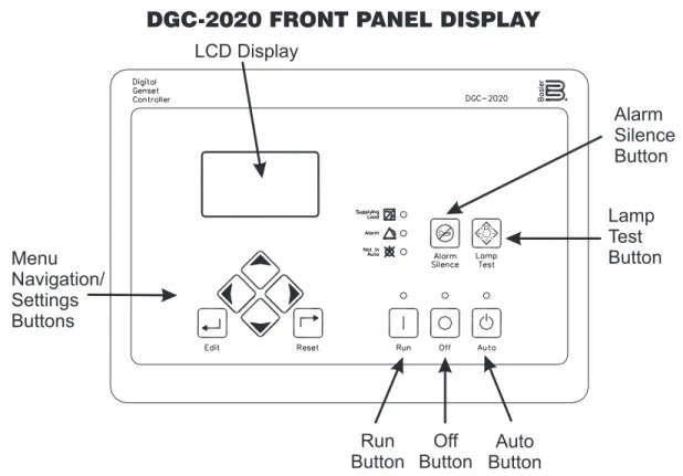
Figure 1 - Front Panel HMI (Human Machine Interface)
DGC-2020 FRONT PANEL DISPLAY
FRONT PANEL LED INDICATORS
Run: Green - Indicates the DGC is in the RUN mode. Off: Red - Indicates the DC is in the OFF mode.
Auto: Green - Indicates the unit is in the AUTO mode of operation.
Supplying Load: Green - Indicates the system is supplying current to a connected load.
Alarm: Red - Indicates an alarm situation by continuous illumination. Indicates a Pre-alarm by flashing. Not in Auto: Red - Indicates unit is not in the AUTO mode.
PACKAGING
DGC-2020 offers a complete system of environmental hardening. Its design utilizes advanced engineering and design techniques to allow it to operate in the harshest environments. The DGC-2020 uses encapsulated construction that has been successfully proven on hundreds of thousands of voltage regulators built by Basler. We have included an inte-grated gasket to seal the front panel to an IP54 rating, and we included a protective cover on the rear of the DGC-2020.
SPECIFICATIONS, continued
over a temperature range of -80°C to +90°C). Please notethat the vibration and temperature extremes noted here are specific to HALT testing and do not reflect recommended operation level.
Agency Approvals
UL/CSA Approvals
"cURus" approved to UL 508 R and CSA C22.2 No.14 NFPA Compliance
Complies with NFPA Standard 110, Standard for Emergency and Standby Power.
CE Compliance
This product complies with the requirements of the following EC Directives:
• Low Voltage Directive (LVD) - 73/23/EEC as amended by 93/68/EEC
• Electromagnetic Compatibility (EMC) - 89/336/EEC as amended by 92/31/EEC and 93/68/EEC
• EN 50178:1997 - Electronic Equipment for use in Power Installations
• EN 61000-6-4:2001 - Electromagnetic Compatibility (EMC), Generic Standards, Emission Standard for Industrial Environments
• EN 61000-6-2:2001 - Electromagnetic Compatibility (EMC), Generic Standards, Immunity for Industrial Environments
Physical
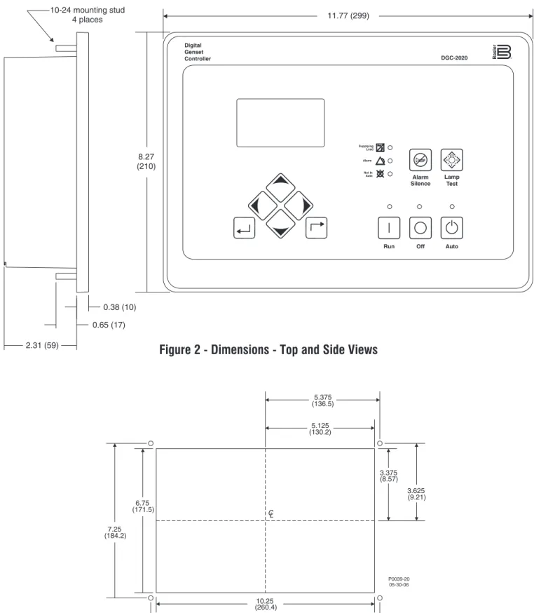
DIMENSIONS
Figure 2 - Dimensions - Top and Side Views
Figure 3 - Panel Cutting and Drilling Dimensions
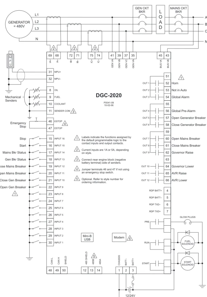
NOTES: 1. Dimensions in parentheses are in millimeters.Figure 4 - DGC-2020 Typical Connections
CONNECTIONS
OPTIONAL FEATURES
ORDERING INFORMATION
STYLE CHART
Route 143, Box 269, Highland, Illinois U.S.A. 62249 Tel +1 618.654.2341 Fax +1 618.654.2351
e-mail: [email protected]
No. 1300 North Zhongshan Road, Wujiang Economic Development Zone Suzhou, Jiangsu Province - P.R. China 215200
Tel +86(0)512 6346 1730 Fax +86(0)512 6346 1760 P.A.E. Les Pins, 67319 Wasselonne Cedex FRANCE
Tel +33 3.88.87.1010 Fax +33 3.88.87.0808 e-mail: [email protected]
The DGC-2020 has been designed to provide maximum functionality at a minimum price. You only need to buy what you need. We have selected options to help maximize the value provided by the DGC-2020.
Additional Contact Outputs
For those applications where more output contacts are needed, the DGC-2020 can be adapted to include 8 additional 2 Adc rated dry contact outputs. These are real contacts and not the solid-state type that require additional external circuitry to properly operate. These contacts are fully programmable via the easy-to-use BESTCOMSPlus PC software and can be assigned for numerous user-defined functions.
RS-485 Communications
When the RS-485 option is selected, the user can send and receive information from the DGC-2020 via the RS-485 commu-nications port and Modbus protocol. This feature allows the DGC-2020 controlled genset to be fully integrated into the building management system. Please see the Instruction Manual for the Modbus register list.
Battery Backup for Real Time Clock
A ten-year (typical life) lithium battery is used to provide long-term maintenance of the real time clock setting. This battery is serviceable by removing the rear cover. Please note that the settings, programming, and event records are saved in non-volatile memory and do not require battery backup.
Internal Modem
The DGC-2020 can provide long distance communications by including an internal modem. There are two modems available, one for U.S. and one for European telephone systems. When a modem is selected, the user can access the DGC-2020 from virtually anywhere via a telephone line. The user can control and monitor the genset as if standing right next to it. The DGC-2020 can also dial out for pre-programmed circumstances to alert the user of selected conditions.
Enhanced Generator Protection
In addition to the standard generator protection (27, 59, 81O, 81U), the DGC-2020 also can be equipped with a more sophisticated generator protection system. This option provides an overcurrent element (51) with 17 selectable time current characteristic curves and a voltage phase balance protection function (47).
Auto-Synchronizer
When the DGC-2020 is configured with this option, the user can select between two types of autosynchronizer, phase lock or anticipatory style. In both methods, the DGC-2020 adjusts generator frequency and voltage to match that of the bus (mains) via contact outputs, then connects the generator to the bus by closing the connecting breaker.
LCD Heater
The standard DGC-2020 is fully functional down to -40