Avaya Solution & Interoperability Test Lab
Configuring Avaya Media Servers as Local Survivable
Processors for Avaya Media Gateways and Standard Local
Survivability on Avaya G250 Media Gateway – Issue 1.0
Abstract
These Application Notes describe how to configure Avaya Media Servers as Local Survivable Processors (LSPs) for Avaya Media Gateways. This includes the configuration required for the Avaya S8300 Media Server as an LSP on Avaya G700 Media Gateway, and the Avaya S8500 Media Server as an LSP for an Avaya G350 Media Gateway. These Application Notes also describe how to configure Standard Local Survivability on the Avaya G250 Media Gateway. The Solution Assurance Credit Card and Banking configuration was used, and these
Application Notes were written at the request of a customer.
WH; Reviewed: PV 4/13/06
Solution & Interoperability Test Lab Application Notes © 2006 Avaya Inc. All Rights Reserved.
1 of 34 lsp-sls.doc
1. Introduction
These Application Notes describe how to configure Avaya Media Servers as Local Survivable Processors (LSPs) for Avaya Media Gateways. This includes the configuration required for the Avaya S8300 Media Server as an LSP on Avaya G700 Media Gateway, and the Avaya S8500 Media Server as an LSP for an Avaya G350 Media Gateway. The Solution Assurance Credit Card and Banking configuration was used to verify these Application Notes.
1.1. Avaya Media Gateway with Local Survivable Processor Overview
The telephone services on the Avaya Media Gateway are controlled by the Media Gateway Controller (MGC). An Avaya G250, G350, or G700 Media Gateway can be administered with an MGC list holding up to four IP addresses. If a media gateway is configured to register to an LSP for network outage protection, the IP address of the LSP is entered at the end of the MGC list. During the network outage, if the media gateway can not communicate to the primary call controllers, the Media Gateway registers to the LSP. The LSP takes over the service to allow the Media Gateway, endpoints, and application servers to continue their operations.
In this sample configuration, there are two Local Survivable Processors, an S8300 Media Server configured as an LSP residing in the Avaya G700 Media Gateway located at Branch 3, and an S8500 Media Server configured as an LSP for the Avaya G350 Media Gateway located at Branch 4. If network communication failure occurs such that the Media Gateways can no longer communicate with the primary call controllers, the S8300 LSP assumes control of the G700 Media Gateway and the S8500 LSP takes over the G350 Media Gateway services. The Media Gateways are configured to automatically return to the primary MGC, when the network communication failure is recovered.
MGC Entry
IP Address Location 1 10.1.2.21 (C-LAN) Main office 2 10.1.2.25 (C-LAN) Main office 3 10.2.2.21 (C-LAN) Branch 2 4 10.13.2.10 (LSP) Branch 3 Table 1: G700 Media Gateway MGC list
MGC Entry
IP Address Location 1 10.1.2.21 (C-LAN) Main office 2 10.1.2.25 (C-LAN) Main office 3 10.2.2.21 (C-LAN) Branch 2 4 10.14.2.9 (LSP) Branch 4 Table 2: G350 Media Gateway MGC list
WH; Reviewed: PV 4/13/06
Solution & Interoperability Test Lab Application Notes © 2006 Avaya Inc. All Rights Reserved.
3 of 34 lsp-sls.doc
1.2. Avaya G250 Media Gateway with Standard Local Survivability
Overview
On a G250 Media Gateway, Standard Local Survivability (SLS) can be enabled to provide limited call processing in survival mode. When SLS is enabled, the G250 Media Gateway will add an IP address on the fifth entry of the MGC list called survivable-call-engine. This entry is always past the transition point.
In the sample configuration, the G250 Media Gateway located at Branch 5 is configured with Standard Local Survivability. When the G250 Media Gateway can not communicate to the active Avaya Communication Manager, SLS is activated. When SLS is active, the G250 Media
Gateway can perform only basic PBX functions. These functions include: • Call capability for analog, DCP, and IP phones
• Outbound dialing through the local PSTN
• Inbound calls from each trunk to pre-configured local analog or IP phones that have registered
• Direct Inward Dialing • Multiple call appearances • Hold and call transfer functions • Contact closure feature
• Local call progress tones (dial tones, busy, etc.)
• Emergency Transfer Relay (ETR) in case of power loss • Automatic return to primary MGC
• IP station registration
1.3. Test Configuration
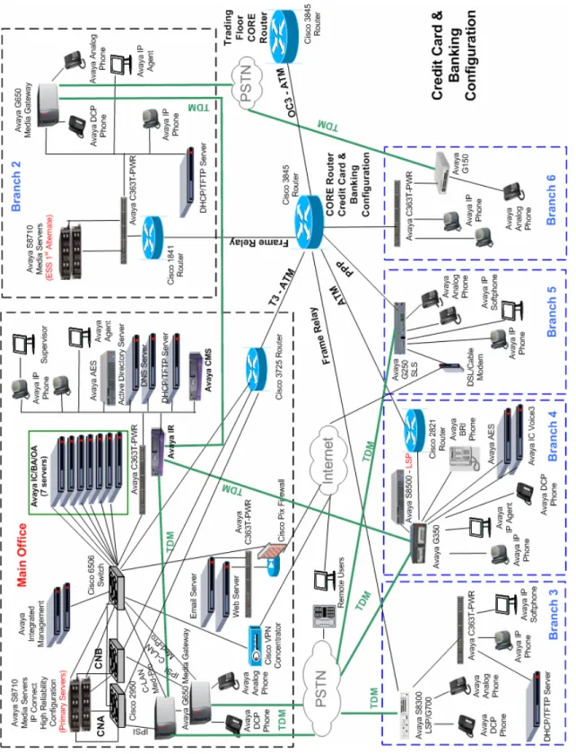
Figure 1 illustrates the Solution Assurance Credit Card and Banking Configuration used to verify these Application Notes. The reference configuration represents a typical financial customer. This is a hub and spoke architecture where the Main Office consists of Avaya S8710 Media Servers with two Avaya G650 Media Gateway carriers in an IP Connect High Reliability configuration. The Branch Offices register to C-LANs in the Avaya G650 Media Gateway at the Main Office. The Branch Offices also have local survivability options. This includes an Avaya S8300 Media Server licensed as an LSP in an Avaya G700 Media Gateway at Branch 3, an Avaya S8500 Media Server also licensed as an LSP at Branch 4, and Standard Local
Survivability mode configured for the Avaya G250 Media Gateway at Branch 5. Each office has trunks to the Public Switched Telephone Network (PSTN). The Main Office also has the Avaya Call Management System, which is used for contact center administration and reporting for all offices. All IP telephones at all offices register to Avaya Communication Manager running on the Avaya S8710 Media Servers at the Main Office.
Figure 1
–
WH; Reviewed: PV 4/13/06
Solution & Interoperability Test Lab Application Notes © 2006 Avaya Inc. All Rights Reserved.
5 of 34 lsp-sls.doc Note: These Application Notes assume that the Avaya Solution Assurance Credit Card and Banking Configuration Release 3.1 reference configuration depicted in Figure 1 is already in place, including Avaya Communication Manager, Avaya Call Management System, Avaya Media Gateways, routers, and switches. Please consult the appropriate documentation listed in the References section of this document for more information on how to set up these
components.
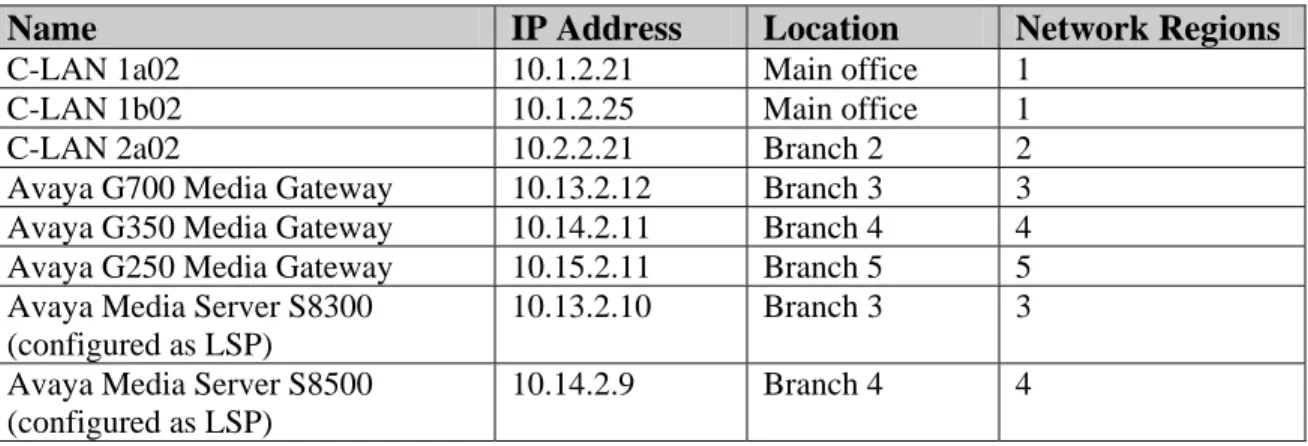
Name IP Address Location Network Regions
C-LAN 1a02 10.1.2.21 Main office 1
C-LAN 1b02 10.1.2.25 Main office 1
C-LAN 2a02 10.2.2.21 Branch 2 2
Avaya G700 Media Gateway 10.13.2.12 Branch 3 3 Avaya G350 Media Gateway 10.14.2.11 Branch 4 4 Avaya G250 Media Gateway 10.15.2.11 Branch 5 5 Avaya Media Server S8300
(configured as LSP)
10.13.2.10 Branch 3 3
Avaya Media Server S8500 (configured as LSP)
10.14.2.9 Branch 4 4
Table 3: IP Address Table
2. Equipment and Software Validated
The following equipment and software were used for the sample configuration provided:
Equipment Software
Avaya Communication Manager
Avaya S8710 Media Server
Avaya S8500 Local Survivable Processor Avaya S8300 Local Survivable Processor
Release 3.1
3.1 (R013x.01.0.628.6) 3.1 (R013x.01.0.628.6) 3.1 (R013x.01.0.628.6) Avaya G650 Media gateway
IPSI (TN2312BP) C-LAN (TN799DP) MEDPRO (TN2602AP) FW 030 FW 017 FW 021
Avaya G700 Media Gateway 25.22.0
Avaya G350 Media Gateway 25.22.0
Avaya G250 Media Gateway 25.22.0
Avaya 4610SW IP Telephone 2.3
Avaya 4620SW IP Telephone 2.3
Avaya 4621SW IP Telephone 2.3
Avaya 4622SW IP Telephone 2.3
3. Configure Local Survivable Processor
3.1. Configure S8500 LSP Server Identity for G350 Media Gateway
This section describes the server configuration steps for the S8500 Local Survivable Processor using the web interface. Launch an Internet browser, and enter the LSP IP address in the address field of the browser:
http://<IP address of the S8500 LSP>
Step Description
Step Description
2. Verify that the LSP has a valid license file installed.
Click on Launch Maintenance Web Interface. The Maintenance Web Pages screen appears. Click on License File, the License File screen appears. Verify the following information:
CommunicaMgr License Mode is Normal.
Network used for License displays the correct Media Gateway address, for example 10.14.2.11.
License Serial Number shows correct Media Gateway serial number.
WH; Reviewed: PV 4/13/06
Solution & Interoperability Test Lab Application Notes © 2006 Avaya Inc. All Rights Reserved.
7 of 34 lsp-sls.doc
Step Description
3. Click on Configure Server. Follow the online instructions and navigate to the Set Identities step. Enter the following values:
Host Name: The LSP host name, for example br4-elsp.
ID : 1
Control Network A: Select Ethernet 0 from the drop down list.
Services Port: Ethernet 1.
Control Network B: UNUSED.
Corporate LAN: Ethernet 0.
Assign the Processor Ethernet to an Interface: Click on Corporate LAN. Click Continue.
WH; Reviewed: PV 4/13/06
Solution & Interoperability Test Lab Application Notes © 2006 Avaya Inc. All Rights Reserved.
9 of 34 lsp-sls.doc Step Description
4. In the Configure Interfaces step, enter the following values:
IP address server1 (br4-lsp): The IP address of the LSP, for example 10.14.2.9.
Gateway: The gateway address, for example 10.14.2.11.
Subnet mask: 255.255.255.0
Speed: Select AUTO SENSE from the drop down list. Click Change.
Step Description
5. In the Configure LSP or ESS step, click on This is a local survivable processor (LSP). Enter the following values:
Registration address at the main server: The C-LAN IP address at the Main office, for example enter 10.1.2.21.
File Synchronization address at the main cluster: The IP addresses of the active and standby media servers at the Main office, for example 10.1.2.11, 10.1.2.12.
3.2. Configure S8300 LSP Server Identity for G700 Media Gateway
This section describes the server configuration steps for the S8300 Local Survivable Processor using the web interface. Launch an Internet browser, and enter the LSP IP address in the address field of the browser:
http://<IP address of the S8300 LSP>
Step Description
1. Log in to the LSP using proper credentials.
WH; Reviewed: PV 4/13/06
Solution & Interoperability Test Lab Application Notes © 2006 Avaya Inc. All Rights Reserved.
11 of 34 lsp-sls.doc
Step Description
2. Verify that the LSP has a valid license file installed.
Click on Launch Maintenance Web Interface. The Maintenance Web Pages screen appears. Click on License File, the License File screen appears. Verify the following information:
CommunicaMgr License Mode is Normal.
Network used for License: MGP.
Step Description
3. Click on Configure Server. Follow the online instructions and navigate to the Set Identities step. Enter the following value:
Host Name: The LSP host name, for example br3-lsp. Click Continue.
WH; Reviewed: PV 4/13/06
Solution & Interoperability Test Lab Application Notes © 2006 Avaya Inc. All Rights Reserved.
13 of 34 lsp-sls.doc
Step Description
4. In the Configure Interfaces step, enter the following values:
IP address server1 (br3-lsp): The IP address of the LSP, for example 10.13.2.10.
Gateway: The gateway address, for example 10.13.2.1.
Subnet mask: 255.255.255.0 Click Change.
Step Description
5. In the Configure LSP step, click on This is a local survivable processor (LSP). Enter the following values:
Registration address at the main server: The C-LAN IP address at the Main office, for example enter 10.1.2.21.
File Synchronization address at the main cluster: The IP addresses of the active and standby media servers at the Main office, for example 10.1.2.11, 10.1.2.12.
Click Change.
WH; Reviewed: PV 4/13/06
Solution & Interoperability Test Lab Application Notes © 2006 Avaya Inc. All Rights Reserved.
15 of 34 lsp-sls.doc
3.3. Configure Avaya Communication Manager for LSP
This section details the administration on Avaya Communication Manager to configure the Local Survivable Processors. The following commands were issued from Avaya Communication Manager SAT screen on the S8710 Media Server at the Main office.
Note: These Application Notes assume that the G700 and G350 Avaya Media Gateways were already configured and registered to the primary MGC.
Step Description
1. Issue the display system-parameters customer-options command and navigate to Page 4. Verify that Local Survivable Processor is set to “y”.
display system-parameters customer-options Page 4 of 11
OPTIONAL FEATURES
Emergency Access to Attendant? y IP Stations? y Enable 'dadmin' Login? y Internet Protocol (IP) PNC? y Enhanced Conferencing? y ISDN Feature Plus? y Enhanced EC500? n ISDN Network Call Redirection? y Enterprise Survivable Server? n ISDN-BRI Trunks? y Enterprise Wide Licensing? n ISDN-PRI? y
ESS Administration? y Local Survivable Processor? y
Extended Cvg/Fwd Admin? n Malicious Call Trace? y External Device Alarm Admin? n Media Encryption Over IP? y Five Port Networks Max Per MCC? n Mode Code for Centralized Voice Mail? n Flexible Billing? n
Forced Entry of Account Codes? n Multifrequency Signaling? y Global Call Classification? n Multimedia Appl. Server Interface (MASI)? n Hospitality (Basic)? y Multimedia Call Handling (Basic)? y Hospitality (G3V3 Enhancements)? y Multimedia Call Handling (Enhanced)? y IP Trunks? y
IP Attendant Consoles? y
Step Description
2. Add entries for the LSPs in the IP NODE NAMES form. Issue the change node-names ip command, and enter the node names for the G700 Media Gateway and G350 Media gateway LSPs and the corresponding IP addresses.
Name and IP Address: Enter the node name br3-lsp with IP address 10.13.2.10 administered in Section 3.2.
Name and IP Address: Enter the node name br4-elsp with IP address 10.14.2.9 administered in Section 3.1.
Submit the changes.
change node-names ip Page 1 of 1
IP NODE NAMES
Name IP Address Name IP Address BO6 10 .16 .2 .10 . . . G250-BR5 10 .15 .2 .11 . . . aesserver 10 .1 .1 .50 br3-lsp 10 .13 .2 .10 . . . . . . br4-elsp 10 .14 .2 .9 . . . br5 10 .15 .2 .10 . . . cc-ess1 10 .2 .2 .11 . . . cc-ess2 10 .2 .2 .12 . . . cf-1a03 10 .1 .2 .15 . . . cf-1b03 10 .1 .2 .17 . . . clan-1a02 10 .1 .2 .21 . . . clan-1a04 10 .1 .2 .23 . . . clan-1b02 10 .1 .2 .25 . . . clan-2a02 10 .2 .2 .21 . . . default 0 .0 .0 .0 . . . WH; Reviewed: PV 4/13/06
Solution & Interoperability Test Lab Application Notes © 2006 Avaya Inc. All Rights Reserved.
17 of 34 lsp-sls.doc
3. To add an LSP, issue the add survivable-processor <xx> command, where <xx> is a node name of an LSP added in Step 2. On Page 1 enter the following value:
Network Region: 3 (As described in Table 3.) Submit the change.
add survivable-processor br3-lsp Page 1 of 3
SURVIVABLE PROCESSOR - PROCESSOR ETHERNET Node Name: br3-lsp
IP Address: 10 .13 .2 .10 Type: LSP
Step Description
4. Repeat Step 3 to add the LSP with node name br4-elsp and Network Region 4 as shown below.
5. Change the gateway automatic recovery rule. Issue the change system-parameters mg-recovery-rule <xx> command, where <xx> is the number of the recovery rule, for example 1. Enter the following value:
Migrate H.248 MG to primary: Enter the MG migration criteria, for example 0-active-calls.
Submit the change.
Note: Depending on the customer recovery requirement, the recovery rule can vary.
change system-parameters mg-recovery-rule 1 Page 1 of 1
SYSTEM PARAMETERS MEDIA GATEWAY AUTOMATIC RECOVERY RULE Recovery Rule Number: 1
Rule Name:
Migrate H.248 MG to primary: 0-active-calls
Minimum time of network stability: 3
WARNING: The MG shall only be migrated when there are no active calls.
add survivable-processor br4-elsp Page 1 of 3
SURVIVABLE PROCESSOR - PROCESSOR ETHERNET Node Name: br4-elsp
IP Address: 10 .14 .2 .9 Type: LSP
Network Region: 4
WH; Reviewed: PV 4/13/06
Solution & Interoperability Test Lab Application Notes © 2006 Avaya Inc. All Rights Reserved.
19 of 34 lsp-sls.doc
Step Description
6. Add a recovery rule on the G700 Media Gateway. Issue the change media-gateway <xx> command, where <xx> is the number of the G700 Media Gateway. Enter the following value:
Recovery Rule: 1 (Rule 1 is defined in Step 5.). Submit the change.
7. Add a recovery rule on the G350 Media Gateway. Issue the change media-gateway <xx> command, where <xx> is the number of the G350 Media Gateway. Enter the following value:
Recovery Rule: 1 (Rule 1 is defined in Step 5.). Submit the change.
change media-gateway 4 Page 1 of 1
MEDIA GATEWAY
Number: 4 IP Address: 10 .14 .2 .11 Type: g350 FW Version/HW Vintage: 25 .22 .0 /1 Name: br4 MAC Address: 00:04:0d:2a:03:d5 Serial No: 05IS37686650 Encrypt Link? y
Network Region: 4 Location: 4
Registered? y Controller IP Address: 10 .1 .2 .21
Recovery Rule: 1 Site Data:
Slot Module Type Name V1: S8300 ICC MM V2: MM712 DCP MM V3: MM710 DS1 MM V4: MM710 DS1 MM V5: MM720 BRI MM V6: MM314 ETH 24P MM V7: 1T+2L-Integ-Analog ANA IMM V8:
V9: gateway-announcements ANN VMM
change media-gateway 3 Page 1 of 1
MEDIA GATEWAY
Number: 3 IP Address: 10 .13 .2 .12 Type: g700 FW Version/HW Vintage: 25 .22 .0 /4 Name: br3 MAC Address: 00:04:0d:8e:74:7d Serial No: 051629400577 Encrypt Link? y
Network Region: 3 Location: 3
Registered? y Controller IP Address: 10 .1 .2 .21
Recovery Rule: 1 Site Data:
Slot Module Type Name V1: S8300 ICC MM V2: MM712 DCP MM V3: MM711 ANA MM V4: MM710 DS1 MM V8: V9: gateway-announcements ANN VMM
3.4. Configure Avaya Media Gateway for LSP
This section details the administration on the Avaya Media Gateways that must be performed to configure the LSP. The Avaya Media Gateways can be accessed via telnet.
Step Description
1. From the PC Windows command prompt enter: telnet <xxxx> where <xxxx> is the IP address of the G350 Media Gateway address, for example 10.14.2.11. Log in to the G350 Media Gateway using the proper credentials.
2. To add the LSP IP address to the MGC list, type set mgc list <LSP IP Address>, as shown below, then press Enter.
Note: The MGC list can be viewed by typing show mgc list.
G350-004(super)# set mgc list 10.14.2.9
Done!
G350-004(super)# show mgc list
CONFIGURED MGC HOST --- 10.1.2.21 10.1.2.25 10.2.2.21 10.14.2.9
Product type: Avaya G350 Media Gateway Release 25.22.0
Login: **** Password: ****
Password accepted (NOTE: You must logoff & login to effect the
permission changes.)
WH; Reviewed: PV 4/13/06
Solution & Interoperability Test Lab Application Notes © 2006 Avaya Inc. All Rights Reserved.
21 of 34 lsp-sls.doc
Step Description
3. The primary search timer is used to search the primary controller. In the sample
configuration, when the main media servers are out of service, it will take about 4 minutes for the G650 Media Gateways to register to the ESS media server. To prevent G350 Media Gateway from registering pre-maturely to the LSP, the primary search timer should set to 5 minutes or more. Type set reset-times primary-search 5 as shown below, and press Enter. Note: The recovery times can be viewed by typing show recovery.
4. From the PC Windows command prompt enter: telnet <xxxx>, where <xxxx> is the IP address of the G700 Media Gateway address, for example 10.13.2.12. Log in to the G700 Media Gateway using the proper credentials.
G350-004(super)# set reset-times primary-search 5
G350-004(super)# show recovery RECOVERY TIMES ---Primary Search : 5 --- Total Search : 30 Transition Point: 3
Product type: Avaya G700 Media Gateway Release 25.22.0
Login: **** Password: ****
Password accepted (NOTE: You must logoff & login to effect the
WH; Reviewed: PV 4/13/06
Solution & Interoperability Test Lab Application Notes © 2006 Avaya Inc. All Rights Reserved.
23 of 34 lsp-sls.doc
Step Description
5. To add the LSP IP address to the MGC list, type set mgc list <LSP IP Address>, as shown below, then press Enter.
Note: The MGC list can be viewed by typing show mgc list.
6. Repeat Step 3 to set primary search timer as shown below.
Note: The recovery times can be viewed by typing show mgp recovery.
cc-g700-003-1(configure)# set mgc list 10.13.2.10
Done!
cc-g700-003-1(configure)# show mgc list
CONFIGURED MGC HOST --- 10.1.2.21 10.1.2.25 10.2.2.21 10.13.2.10 cc-g700-003-1(super)# configure
cc-g700-003-1(configure)# set mgp reset-times primary-search 5
cc-g700-003-1(super)# show mgp recovery
MGP RECOVERY TIMES
---
Primary Search : 5
Total Search : 30 Transition Point: 3
4. Configure Standard Local Survivability (SLS) for Avaya
G250 Media Gateway
4.1. Configure SLS on Avaya Communication Manager
This section details the administration on Avaya Communication Manager which must be performed to configure the Standard Local Survivability (SLS). The following commands were issued at the Avaya System Access Terminal (SAT) screen on the S8710 Media Server at the Main office.
Step Description
1. Add an entry for the G250 Media Gateway in the IP NODE NAMES form. Issue the change node-names ip command, and enter the following values:
Name: The G250 Media Gateway node name, for example G250-BR5
IP Address: The G250 Media Gateway IP address, for example 10.15.2.11. Submit the changes.
change node-names ip Page 1 of 1
IP NODE NAMES
Name IP Address Name IP Address BO6 10 .16 .2 .10 G250-BR5 10 .15 .2 .11 . . . . . . aesserver 10 .1 .1 .50 . . . br3-lsp 10 .13 .2 .10 . . . br4-elsp 10 .14 .2 .9 . . . br5 10 .15 .2 .10 . . . cc-ess1 10 .2 .2 .11 . . . cc-ess2 10 .2 .2 .12 . . . cf-1a03 10 .1 .2 .15 . . . cf-1b03 10 .1 .2 .17 . . . clan-1a02 10 .1 .2 .21 . . . clan-1a04 10 .1 .2 .23 . . . clan-1b02 10 .1 .2 .25 . . . clan-2a02 10 .2 .2 .21 . . . default 0 .0 .0 .0 . . .
WH; Reviewed: PV 4/13/06
Solution & Interoperability Test Lab Application Notes © 2006 Avaya Inc. All Rights Reserved.
25 of 34 lsp-sls.doc
Step Description
2. Gatekeeper information needs to be administered for all IP stations on the G250 Media Gateway. Issue the change station <xxxx> command, where <xxxx> is the extension number of the IP station, for example 25002. Enter the following value:
Survivable GK Node Name: Enter the node name, defined in Step 1, G250-BR5. Submit the change.
change station 25002 Page 1 of 4
STATION
Extension: 25002 Lock Messages? n BCC: 0 Type: 4625 Security Code: * TN: 1 Port: S00014 Coverage Path 1: COR: 1 Name: BO5 AGENT 2 Coverage Path 2: COS: 1 Hunt-to Station:
STATION OPTIONS
Loss Group: 19 Personalized Ringing Pattern: 1 Message Lamp Ext: 25002 Speakerphone: 2-way Mute Button Enabled? y Display Language: english Expansion Module? n
Survivable GK Node Name: G250-BR5
Survivable COR: unrestricted Media Complex Ext: Survivable Trunk Dest? y IP SoftPhone? n
Customizable Labels? y
4.2. Configure Standard Local Survivability for Avaya G250 Media
Gateway
This section details the administration on the Avaya G250 Media Gateway that are performed to configure the Standard Local Survivability (SLS). The following commands are issued at the Avaya G250 Media Gateway using the Command Line Interface (CLI). The Avaya G250 Media Gateway can be accessed via telnet.
Step Description
1. From the PC Windows command prompt enter: telnet <xxxx> where <xxxx> is the IP address of the G250 Media Gateway address, for example 10.15.2.11. Log in to G250 Media Gateway using the proper credential.
2. To enable survivable call engine, type the set survivable-call-engine enable command, as shown below. Press Enter.
3. To enter the survivable-call-engine configuration mode, type survivable-call-engine, as shown below. Press Enter.
4. To add a new IP station, type station <xxxx> <class>, where <xxxx> is the station
extension, and <class> is the type of the phone. For this example, the G250 Media Gateway only supports analog and IP stations. Type station 25001 ip. Press Enter. The prompt is at the level two Command Line Interface, as shown below.
G250-005(super-survivable-call-engine)# station 25001 ip
Done!
G250-005(super-survivable-call-engine/station 25001)#
G250-005(super)# set survivable-call-engine
Survivable Call Engine is enabled
G250-005(super)# survivable-call-engine
G250-005(super-survivable-call-engine)#
Product type: Avaya G250 Media Gateway Release 25.22.0
Login: **** Password: ****
Password accepted (NOTE: You must logoff & login to effect the
WH; Reviewed: PV 4/13/06
Solution & Interoperability Test Lab Application Notes © 2006 Avaya Inc. All Rights Reserved.
27 of 34 lsp-sls.doc
Step Description
5. Issue the following station sub-commands to set the IP station parameters. Press Enter after each sub-command.
set cor <xx>, where <xx> is the class of restriction, for example unrestricted.
set password <****>, where <****> is the password of the IP station.
set trunk-destination yes. This allows the station to receive analog loop-start trunk calls.
set type <xx>, where <xx> is the phone type, for example ip4620sw.
When finished with all sub-commands, type exit and then press Enter to return to the level one Command Line Interface. The result is displayed as shown below:
6. Repeat Steps 4 and 5 to add the remaining IP stations. The results can be viewed by typing show extension as shown below:
G250-005(super-survivable-call-engine)# show extension
Extension Type Port Cor Trk-Des Exp-Mod Flash Passwd
--- - --- --- --- --- - --- ---
25001 ip4620sw 255.255.255.255 unrestricted yes no - ******
25002 ip4625sw 255.255.255.255 unrestricted yes no - ******
25004 ip4620sw 255.255.255.255 unrestricted yes no - ******
G250-005(super-survivable-call-engine)# show ext
Extension Type Port Cor Trk-Des Exp-Mod Flash Passwd --- --- --- --- --- --- --- ---
25001 ip4620sw 255.255.255.255 unrestricted yes no - ******
Step Description
7. Repeat Step 4 to add an analog station. Type station 25011 analog, and press Enter. Issue the following analog station sub-commands to set the analog station parameters. Press Enter after each sub-command.
set cor <xx>, where <xx> is the class of restriction, for example unrestricted.
set port <vxxx>, where <vxxx> is the physical port on the analog module, for example v305.
set trunk-destination yes.
set flash yes. (If switch hook flash signal is required.)
When finished with all sub-commands, type exit and then press Enter to return to the level one Command Line Interface. The result can be viewed by typing show extension as shown below:
8. Repeat Step 7 to add the remaining analog stations. The result can be viewed by typing show extension as shown below:
G250-005(super-survivable-call-engine)# show extension
Extension Type Port Cor Trk-Des Exp-Mod Flash Passwd --- --- --- --- --- --- --- --- 25001 ip4620sw 255.255.255.255 unrestricted yes no - ****** 25002 ip4620sw 255.255.255.255 unrestricted yes no - ****** 25004 ip4620sw 255.255.255.255 unrestricted yes no - ******
25011 analog2500 v305 unrestricted yes - yes
25012 analog2500 v306 unrestricted yes - yes
-G250-005(super-survivable-call-engine)# show extension
Extension Type Port Cor Trk-Des Exp-Mod Flash Passwd --- --- --- --- --- --- --- --- 25001 ip4620sw 255.255.255.255 unrestricted yes no - ****** 25002 ip4620sw 255.255.255.255 unrestricted yes no - ****** 25004 ip4620sw 255.255.255.255 unrestricted yes no - ******
25011 analog2500 v305 unrestricted yes - yes -
WH; Reviewed: PV 4/13/06
Solution & Interoperability Test Lab Application Notes © 2006 Avaya Inc. All Rights Reserved.
29 of 34 lsp-sls.doc
Step Description
9. To add a trunk group, type trunk-group <id> <type>, where
<id> The unique identifier of the trunk group, for example 3.
<type> The trunk-group type, for example loop-start. Press Enter.
10. Issue the following trunk-group sub-commands to set the trunk-group parameters. Press Enter after each sub-command.
add port <xx>, where <xx> is the trunk-group port number, for example v303.
set dial <rotary | dtmf>. Sets how the trunks in the current trunk group dial.
set tac <xx>, where <xx> is the trunk access code, for example 5003.
When finished with all sub-commands, type exit and then press Enter to return to the first level Command Line Interface.
The sequence of commands is shown below.
G250-005(super-survivable-call-engine/trunk-group 3)# add port v303
Done!
G250-005(super-survivable-call-engine/trunk-group 3)# set dial dtmf
Done!
G250-005(super-survivable-call-engine/trunk-group 3)# set tac 5003
Done!
G250-005(super-survivable-call-engine/trunk-group 3)# exit
Done!
G250-005(super-survivable-call-engine)#
G250-005(super-survivable-call-engine)# trunk-group 3 loop-start
Step Description
11. Repeat Steps 9 and 10 to add all remaining trunk groups. The results can be viewed by typing show trunk-group as shown below:
12. Configure the dial pattern by typing set dial-pattern <dialed_string> <length> <type> <deny> <trunk_grp>, where
<dialed string>: dialed string, for example 6.
<length>: length of the dialed string, for example 5.
<type>: locl
<deny>: false
<trunk_grp>: trunk group number, for example 1. Press Enter.
The screen is displayed as shown below.
13. To configure an IP codec set within the SLS data set, type set ip-codec-set <codec>, where
Codec: is the codec type, for example g.711mu. Press Enter.
G250-005(super-survivable-call-engine)# set ip-codec-set g.711mu
G250-005(super-survivable-call-engine)# set dial-pattern 6 5 locl false 1
G250-005(super-survivable-call-engine)# show trunk-group
Group Type Dial Tac Ports Supervision Treat Insert --- --- --- ---- --- --- --- ---
1 loop-start dtmf 5001 v301 - - -
2 loop-start dtmf 5002 v302 - - -
3 loop-start dtmf 5003 v303 - - -
WH; Reviewed: PV 4/13/06
Solution & Interoperability Test Lab Application Notes © 2006 Avaya Inc. All Rights Reserved.
31 of 34 lsp-sls.doc
Step Description
14. Feature Access Codes (FAC) need to be programmed on the G250 Media Gateway. These include ars1, ars2, hold, contact-open, contact-close, and contact-pulse (Detailed
information can be found in [2]). The FAC for hold is shown below.
To set the Feature Access Code, type set fac <feature> <fac>, where
<feature>: hold
<fac>: is the feature access code, for example *3. Press Enter.
The screen is displayed as shown below.
Note: When in SLS mode, a user can press switch-hook flash and dial *3 to place the analog station on the hard hold state.
15. Repeat Step 14 to add the other FACs.
16. To set the maximum number of IP phones that can be registered, type set max-ip-registrations <xx>, where
<xx> is the maximum number of IP registrations allowed, for example 6.
Note: The default number of registrations is 8. The maximum number of max-ip-registrations is 12.
G250-005(super-survivable-call-engine)# set fac hold *3
5. Verification Steps
Step Description1. Issue the list survivable-processor command on the main media server. • Verify that both LSPs are registered to the Main Media Server. • Verify that LSP translations are updated.
2. Disconnect the network Ethernet cables from the Main and ESS Media Servers. • Verify that the LSPs become active.
• Verify that the G700 Media Gateway at Branch 3 is registered to the S8300 LSP and the G350 Media Gateway at Branch 4 is registered to the S8500 LSP.
• Verify that IP phones are registered to the proper LSP.
• Verify that intra Media Gateway calls can be placed between the different types of phones.
• Verify that conference calls can be established within an office. 3. Reconnect the network Ethernet cables to the Main Media Server.
• Verify that the Media Gateways automatically return to the Main Media Server when there are no active calls and the network has been stabilized for more than 3 minutes (The recovery rule 1 was defined in Section 3.3 Step 5).
• Verify that the LSPs are registered to the Main Media Server.
4. Disconnect the Branch 5 Ethernet cable which is connected to the Cisco router 3845. • Verify that SLS becomes active after primary search timeout.
• Verify that the IP phones on Branch 5 are registered after SLS activated. • Verify that IP/analog station to station calls have two-way talk path. • Verify that IP/analog station to station calls can be transferred. • Verify that IP/analog station calls can be held and un-held.
• Verify that IP/analog phones can call and receive calls to/from the PSTN and have two way talk path.
5. Reconnect the Ethernet cable to Branch 5.
• Verify that the Media Gateways does not auto fallback to Main Media Server, since there is no recovery rule added on the G250 Media Gateway.
Add a recovery rule to the G250 Media Gateway as described in Section 3.3 Step 7.
• Verify that the G250 Media Gateway can automatically fallback to the Main Media Server after network failure recovery.
list survivable-processor
SURVIVABLE PROCESSORS
Name Type IP Address Reg LSP Translations Net Act Updated Rgn
br3-lsp LSP 10 .13 .2 .10 y n 13:20 2/15/2006 3
cc-ess1 ESS 10 .2 .2 .11 y 22:00 2/14/2006 1 cc-ess2 ESS 10 .2 .2 .12 n 22:00 2/14/2006 1
WH; Reviewed: PV 4/13/06
Solution & Interoperability Test Lab Application Notes © 2006 Avaya Inc. All Rights Reserved.
33 of 34 lsp-sls.doc
6. Conclusion
These Application Notes demonstrate how to provision Local Survivable Processors for Avaya Media Gateways. In addition, these Application Notes also describe the steps required to configure Standard Local Survivability on an Avaya G250 Media Gateway.
7. Additional References
The following documents can be found at http://support.avaya.com:
[1] Administrator’s Guide for Avaya Communication Manager, Issue 2, February 2006; Doc
ID: 03-300509
[2] “Avaya G250 and Avaya G350 CLI Reference”, Issue 2, February 2006; Doc ID: 03-300437.
[3] “Administration for the Avaya G250 and Avaya G350 Media Gateways”, Issue 2, February 2006; Doc ID: 03-300436.
©2006 Avaya Inc. All Rights Reserved.
Avaya and the Avaya Logo are trademarks of Avaya Inc. All trademarks identified by ® and ™ are registered trademarks or trademarks, respectively, of Avaya Inc. All other trademarks are the property of their respective owners. The information provided in these Application Notes is subject to change without notice. The configurations, technical data, and recommendations provided in these Application Notes are believed to be accurate and dependable, but are
presented without express or implied warranty. Users are responsible for their application of any products specified in these Application Notes.
Please e-mail any questions or comments pertaining to these Application Notes along with the full title name and filename, located in the lower right corner, directly to the Avaya Solution & Interoperability Test Lab at [email protected]