Shaft Design under Fatigue Loading By Using Modified Goodman
Method
R. A. Gujar
1, S. V. Bhaskar
21, 2 (Department of Mechanical Engineering, Pune University, Maharashtra
ABSTRACT
In this paper, shaft employed in an Inertia dynamometer rotated at 1000rpm is studied. Considering the system, forces, torque acting on a shaft is used to calculate the stresses induced. Stress analysis also carried out by using FEA and the results are compared with the calculated values. Shaft is having varying cross sections due to this stress concentration is occurred at the stepped, keyways ,shoulders, sharp corners etc. caused fatigue failure of shaft. So, calculated stress concentration factor from which fatigue stress concentration factor is calculated. Endurance limit using Modified Goodman Method, fatigue factor of safety and theoretical number cycles sustained by the shaft before failure is estimated and compared results with FEA.
Keywords
–
Dynamometer, Factor of Safety, Fatigue, FEA Goodman, Stress Concentration.I.
Introduction
A shaft is a rotating member, usually of circular cross-section for transmitting power. It is supported by bearings and supports two flywheels. It is subjected to torsion, and bending in combination. Generally shafts are not of uniform diameter but are stepped, keyways, sharp corners etc. The stress on the shaft at a particular point varies with rotation of shaft there by introducing fatigue. Even a perfect component when repeatedly subjected to loads of sufficient magnitude, will eventually propagate a fatigue crack in some highly stressed region, normally at the surface, until final fracture occurs. Extensive work has been carried out by failure analysis research community investigating the nature of fatigue failures using analytical, FEA and experimental methods [1]. According to Osgood all machine and structural designs are problems in fatigue [2]. Failure of an elevator shaft due torsion-bending fatigue was given in [3]. The failure of a shaft due improper fastening of support was explained in [4]. Accurate stress concentration factors for shoulder fillet in round and flat bars for different loading conditions are given in [5]. Failure analysis of a locomotive turbocharger main-shaft and rear axle of an automobile was discussed in [6,7]. Celalettin Karaagac and M.Evren Toygar considered an agitator shaft with a circumferential groove for
which the fatigue life has been estimated [8]. Michele Zappalorto, Filippo Berto and Paolo Lazzarin predicted the notch stress concentration factors of round bars under torsion [9].
II. Theory
Inertia dynamometer is operated to generate necessary inertia/torque is used to check performance characteristics of engine. Here, shaft is simply supported in bearing at two ends with subjected load of two flywheels fixed & removable and self weight of shaft as shown in Fig.1 and the specifications in Table1.
Figure.1 Free body diagram of inertia dynamometer
Table.1 Specifications of Inertia Dynamometer RA
Reaction at Bearing on other
side point A. (kg) 5013
RB
Reaction at Bearing on the
Motor Side point B.( kg) 6427
W Weight of Shaft (kg) 3100
W1 Weight of Fixed Flywheel(kg) 1340
W2 Weight of Removable
Flywheel(kg) 7000
Tmax Maximum Torque on Shaft
(kg-m) 1800
Tmin Minimum Torque on Shaft
(kg-m) 449
N Rotational Speed(rpm) 1000
d Minimum shaft diameter (mm) 330
2.1Selection and Use of Failure Theory
Here select the Distortion energy theory for fatigue failure analysis to find maximum stress values because there is combined loading of bending and torsion. Distortion energy theory is used when the factor of safety is to be held in close limits and the
cause of failure of the component is being investigated. This theory predicts failure most accurately for ductile material. But design calculations involved in this theory are slightly complicated as compared with other theories of failure. The below equation (1-2) is for design of shaft for fluctuating load (Case-II reversed bending with reversed torsion) calculated von-Mises stress. According to the distortion energy theory,
(1)
From, Design of safety,
(2) Where, h (MPa) = factor of Safety.
2.2 Modified Goodman Method
The modifying endurance limit of the shaft is found using Modified Goodman equation by taking mean stress ( in to account. Modified Goodman curve is a plot between the mean stress along X-axis and amplitude stress along Y-axis as shown in fig.2 and The equation (3) is represented as below
Figure.2 Fatigue diagram showing various criteria of failure.
By Modified Goodman Equation, +
= 1 (3)
Factor of safety is calculated for High cycle Fatigue applications from above eqn (3).
We know that;
fatigue failure safety is,
factor of safety < 1 Design is fail
factor of safety > 1 Design is safe. (4) where,
Yield tensile strength (MPa)
2.3 Fluctuating Stresses-Design for Finite and Infinite Life
There are two types of problems in fatigue design-(i) components subjected to completely reversed stresses, and (ii) components subjected to
fluctuating stresses. the mean stress is zero in case of completely reversed stresses. But, in case of fluctuating stresses, there is always a mean stress and the stresses can be purely tensile, purely compressive or mixed depending upon the magnitude of the mean stress. Such a problems are solved by Modified Goodman diagram, which will be discussed in section 2.2.The design problems for fluctuating stresses are further divided into two groups-(i) design for infinite life, and (ii) design for finite life.
2.3.1 Design for Infinite Life
When the component is to be designed for infinite life, the endurance limit becomes the criteria of failure. The amplitude stress induced in such components should be lower than the endurance limit in order to withstand the infinite number of cycles. Such a components are designed with the help of following equation (5):
The S-N curve as shown in fig.3.The curve is valid for steels
Figure.3 S-N curve for steel.
2.4 Material Properties
The CAD model of the shaft with its components is shown in fig.4.The material of the shaft under consideration is Fe410W-A (EN10025)-IS2062.Mechanical properties are shown in Table.2. The Material S-N curve shown in the fig.5. From material curve it is seen that at certain stress range the curve becomes straight, this means that material is having infinite life below that stress. Also, validate design stresses to compare alternating / mean stress value [log10 ( of material
through graph with induced stresses of inertia dynamometer. The stresses should be within limit than stress value of material by this it is concluding in further section whether induced / working stresses are safe or not.
Figure.4 CAD model of inertia dynamometer
Figure.5 Material Curve for EN10025 Table.2 Material Properties of Shaft Physical Properties Values
Ultimate Strength ( ) 410 Mpa (N/mm2)
Yield Strength ( ) 230 Mpa (N/mm2) Young’s Modulus (E) 2.1x10⁵ N/mm2 Poisson’s Ratio 0.3
Density 7850 kg/ m3
III.
3. Fatigue Analysis by Analytical
Approach
In this section, calculated the von-Mises (equivalent) stress ( , factor of safety ( ),
Number of cycles(N) resp.
Initially, calculated Maximum and minimum bending moments at different points,
Maximum Bending Moment at D = 57.84 x 10⁶ N-mm
Minimum Bending Moment at E = 35.11 x 10⁶ N-mm.
(Mb)Max=57.84 x 10⁶ N-mm.
(Mb)Min= 35.11 x 10⁶ N-mm. Then,
I.To find Mean & Amplitude Stresses.
(Mb)m= ( (Mb)max + (Mb)min ) (6) (Mb)m= 46.475 X 10 6 N-mm. (Mb) a = ( (Mb)max - (Mb)min ) (7) (Mb) a = 22.73 X10⁶ N-mm. (Mt) max = 1800 kg-m = 18 X 106 N-mm (given) (Mt) min = 449 kg-m = 4.49 X 10⁶ N-mm (given) σxm= (8) σxm = 13.17 N/mm2 σxa = (9) σxa = 6.44 N/mm2 = (10) = 2.24 N/mm2 = (11) = 0.636 N/mm2 = √ + 3 (12)
Also, calculate log stress values, log ( ) log( Pa (13) = +3 (14) log ( ) log ( Pa (15) Since,
So, we can say that,
The von-Mises/equivalent stresses are38.26N/mm2
tan = & also, tan θ = (16) tan θ =0.483
tan θ =0.4877
II.To find Endurance Strength ‘ ,
= X X X Ktemp X Kreliability X Kd X Kstress concentration X (17) But, = 0.5 (18) = 0.5 (410) = 205 N/mm2 , , Ktemp= 1 for T≤ 450 = 4.51(410)0.265= 0.92 , Kreliability =90 % =0.897, Kd= = =0.35. = 1*0.75*0.92*1*0.897*0.35*205 By Modified Goodman Equation,
= 38.26 N/mm2
(15)
= 44.4082 N/mm2
= 38.26 N/mm2=38.26*
+
= 1
(19)Put above values,
+
= 1
=65.23 N/ =31.81 N/FOS=
Step III : To find Number of Cycles from S-N Construction = = 0.9 =0.9(410) = 369 Mpa log10(0.9 = 2.5670 log10( = 1.6474 log10( = 1.3090 log10(N
=
log10(N)Since, Infinite number of cycles more than 1x 10⁶ cycles.
IV.
Fatigue Analysis by FEA Approach
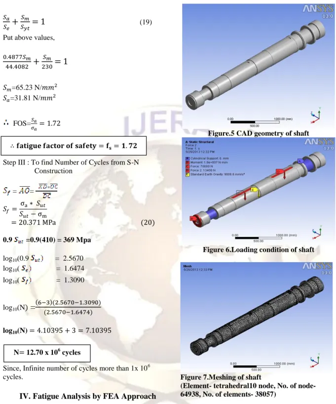
Figure.5 CAD geometry of shaft
Figure 6.Loading condition of shaft
Figure 7.Meshing of shaft
(Element- tetrahedral10 node, No. of node- 64938, No. of elements- 38057)
Figure 8.Equivalent / von-mises stresses of shaft
Figure 9. Fatigue factor of safety
Figure 10. Number of fatigue life cycles
V.
Results and Discussion
Table.3 Comparison of Analytical and FEA
Analytical Approach FEA Approach
= 1.72 = 2.59
Infinite Life Infinite Life
From above Table.3 it is clear that, the fatigue analysis of Inertia Dynamometer shaft gives close results by Analytical and FEA approach. From optimization point of view the FEA analysis is very useful tool. Also, to change the material having low
value of then to reduced the value of fatigue
factor of safety up to 1.5 for saving cost of material. Software used for fatigue analysis CATIA V5, ANSYS13 which gives moderate results.
VI.
Conclusion
The fatigue life prediction is performed based on finite element analysis and analytical method. Using the constant amplitude loading, the fatigue life of the dynamometer shaft has been predicted. This study will help to understand more the behavior of the dynamometer shaft and give information for the manufacturer to improve the fatigue life of the dynamometer shaft using FEA tools. It can help to reduce cost, critical speed and times in research and development of new product. From eqn (13) & (15), logarithmic alternating / mean stress values 7.2 Pa & 7.5 Pa which are less than material alternating stress value of 7.94 Pa from fig.(5). So, conclude that, the working alternating / mean stress within limit value and increased fatigue strength for infinite life below material endurance strength limit.
Also, it is clear from above results, Von-Mises stress value by analytical approach 38.26
N/mm2 which are nearly same by using FEA approach having difference of 10% in both results which is acceptable range.
The fatigue factor of safety calculated from eqn(19) is 1.72 & by FEA approach 2.59 again these values are approximately same.The number of life cycles are calculated by using modified Goodman method from S-N construction are 12.70 * cycles and by using FEA it will show safely run at 1* cycles.So,it will show infinite life cycle checked at High cycle fatigue.
VII.
Acknowledgement
I wish to express my sincere thanks to Prof. A.G. Thakur (HOD of Mechanical Department) for their technical support and helpful attitude gave us high moral support without which it would have been impossible for me to present and complete this work successfully.
Finally, I specially wish to thank my Father and Mother, wife Kirti and sweet daughter Sanskriti and all those who gave me valuable inputs directly or indirectly in making this work a success.
R
EFERENCESJournal Papers:
[1] Rice RC, Fatigue design handbook,3rd ed. York: SAE;1997.
[2] Osgood CC, Fatigue design, Oxford: Pergamon press;1982.
[3] A.Goksenli, I.B. Eryurek, Failure analysis of an elevator drive shaft, Engineering failure analysis 16 (2009) 1011-1019
[4] S.Cicero, R.Cicero, R.Lacalle, G.Diaz, D.Ferreno,Failure analysis of a lift gear shaft: application of the FITNET FFS procedure fatigue module, Engineering fracture analysis 15 (2008) 970-980. [5] Nao-Aki Noda, Yasushi Takase and Keiji
Monda,Stressconcentration factors for shoulder fillets in round and flat bars under various loads,Int. J. fatigue vol19 no.1, pp. 75-84,1997
[6] Xu Xiaolei, Yu Zhiwei,Failure analysis of a locomotive turbo-charger main-shaft,Engineering fracture analysis16 (2009) 495-502.
[7] Osman Asi,Fatigue failure of a rear axle shaft of an Automobile,Engineering failure analysis 13 (2006) 1293-1302.
[8] Celalettin Karaagac, M.Evren Toygar,Fracture and fatigue analysis of an agitator shaft with a circumferential notch,Engineering fracture mechanics 73 (2006) 2034-2052
[9] Michele Zappalorto, Filippo Berto, Paolo Lazzarin,Practical expressions for the notch stress concentration factors of round bars under torsion, International fatigue journal 33 (2011) 382-395
[10] Deepan Marudachalam M.G,K.Kanthavel, R.Krishnaraj, Optimization of shaft design under fatigue loading using Goodman method, International Journal of Scientific & Engineering Research, Volume 2, Issue 8, August-2011.
Books:
[11] V.B.Bhandari, Design of Machine Element, (Tata McGraw-Hill Publication. New
Delhi.2004)
[12] Budynas−Nisbett,Shigley’sMechanical Engineering Design,(McGraw−Hill Primis, Eighth Edition,New Delhi,2008)
Thesis:
[13]Celalettin KARAAĞAÇ, Fracture and fatigue analysis of an agitator shaft with a cicumferential notch, doctoral diss., Graduate School of Natural and Applied Sciences,Dokuz Eylül University 2002.