Vocia MS-1 Network Considerations for VoIP
Vocia software rev. 1.4 or higher requiredVocia MS-1 and Network Port Configuration
The Vocia Message Server 1 (MS-1) has a number of roles in a Vocia Paging System. It is able to be used for storage and delivery of Pre-Recorded messages, Email reporting, Message Scheduling, Inter-World communications, system logging ,serving Device Configuration automatically and as an Interface to third party control. An MS-1 also allows Control communication between devices in a Vocia World and a PC using Vocia control software and has a built in VoIP interface for User Recorded Live Pages or Pre Recorded Paging. There are a number of Call Manager specific Technical Notes can be reviewed for more details of connection settings.
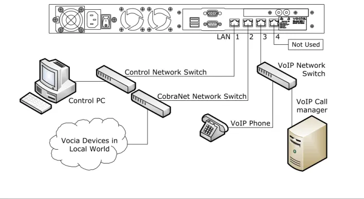
To facilitate the features of the MS-1 is fitted with four RJ45 Ethernet ports to accommodate multiple network topologies. Looking at the rear of the unit these ports are:
- LAN-1: Control - LAN-2: CobraNet - LAN-3: VoIP - LAN-4: Not Used
This document outlines the requirements for configuring the MS-1 IP Control network and VoIP interface and will be focusing on the role of the LAN-1 and LAN-3 ports.
LAN-2 is used for connection to a CobraNet network to allow sharing of control and audio data to other Vocia devices. This is a layer 2 protocol that does not use logical addressing and is not routable. For more information on CobraNet refer to the separate CobraNet Technical Note.
It is recommended that each of the MS-1 LAN ports be connected to separate networks as shown in figure 1.
VoIP Call manager Control PC CobraNet Network Switch
Vocia Devices in Local World
VoIP Network Switch Control Network Switch
3 2 1
LAN 4
Not Used
VoIP Phone
VoIP and Control on different networks, single VoIP network
This is the recommended method to configure a Vocia system that requires VoIP paging. This example assumes a valid IP connection is configured between the MS-1 and the control computer and that the Vocia software is online.
The MS-1 supports segregating traffic to separate networks. In this configuration the LAN-1 Control Port and LAN-3 VoIP port are on different physical network segments. The VoIP port must be configured to use different IP and Gateway settings to the Control network. All the VoIP phones that communicate to the MS-1 are on the same network as the Call Manager and the MS-1 VoIP port.
MS-1 IP: 192.168.1.101
Switch Call Manager IP: 10.10.1.50 Control PC
IP: 192.168.1.110
Switch
VoIP IP: 10.10.1.100
LAN-1 LAN-3
Figure 2- Setup for Control and VoIP on different networks. No VoIP Static Routes required.
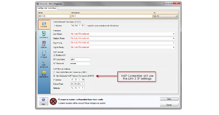
Using the Vocia Software, in the MS-1 Properties dialog > VoIP General section, Enable VoIP and confirm the VoIP Network Settings Radio button is set to Use Dedicated VoIP Network Connection (LAN-3). The examples will show LAN-1 using the default MS-1 IP address of 192.168.1.101 while LAN 3 will use the IP address of 10.10.1.100 and 10.10.1.1 gateway.
VoIP and Control on different networks, multiple VoIP subnets
In facilities that utilize a more advanced VoIP configuration, there may be a requirement for a VoIP network that spans multiple networks. Two topologies are supported. If the requirement is that multiple subnets are required this can either be facilitated by defining multiple routes within a single router. Please see figure 4. Alternatively, multiple routers can also be supported as additional VoIP routes to each gateway can be defined in the MS-1. Please see figure 5.
Multiple VoIP networks with single gateway
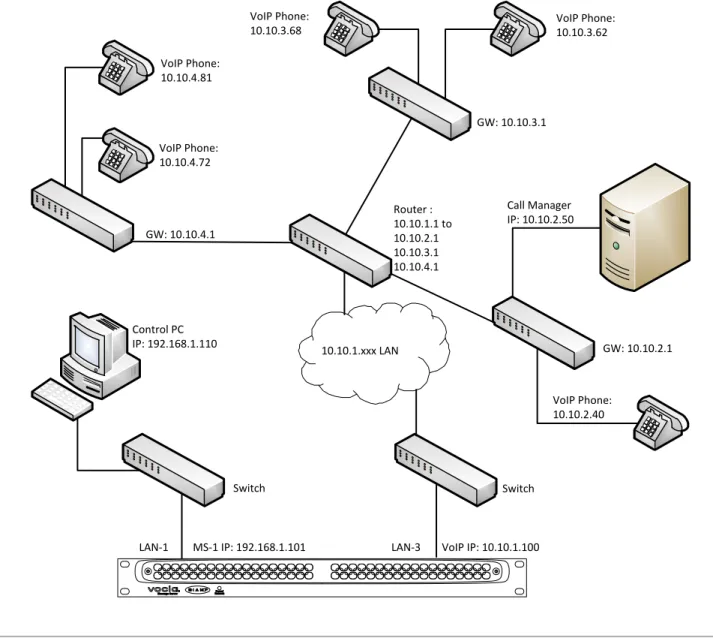
A local router can be configured to route from the local VoIP network to multiple destination gateways. This would be a function of the network router as the MS-1 VoIP interface is only required to reach the local 10.10.1.1 gateway. The following diagram shows a common example where VoIP phones, the Call Manager and the MS-1 are on different networks. In this case there are three additional gateways defined in the network router so that the default 10.10.1.1 gateway routes to destinations 10.10.2.1, 10.10.3.1 and 10.10.4.1 .
Switch Control PC
IP: 192.168.1.110
Switch
Call Manager IP: 10.10.2.50 GW: 10.10.3.1
GW: 10.10.4.1
VoIP Phone: 10.10.3.62
VoIP Phone: 10.10.4.72 VoIP Phone: 10.10.4.81
VoIP Phone: 10.10.3.68
MS-1 IP: 192.168.1.101 VoIP IP: 10.10.1.100
VoIP Phone: 10.10.2.40
LAN-1 LAN-3
Router : 10.10.1.1 to 10.10.2.1 10.10.3.1 10.10.4.1
10.10.1.xxx LAN GW: 10.10.2.1
Figure 4 - Setup for Control and VoIP on different networks with single gateway. Additional routes will be required to allow communication between Network Segments.
Multiple VoIP networks with multiple gateway
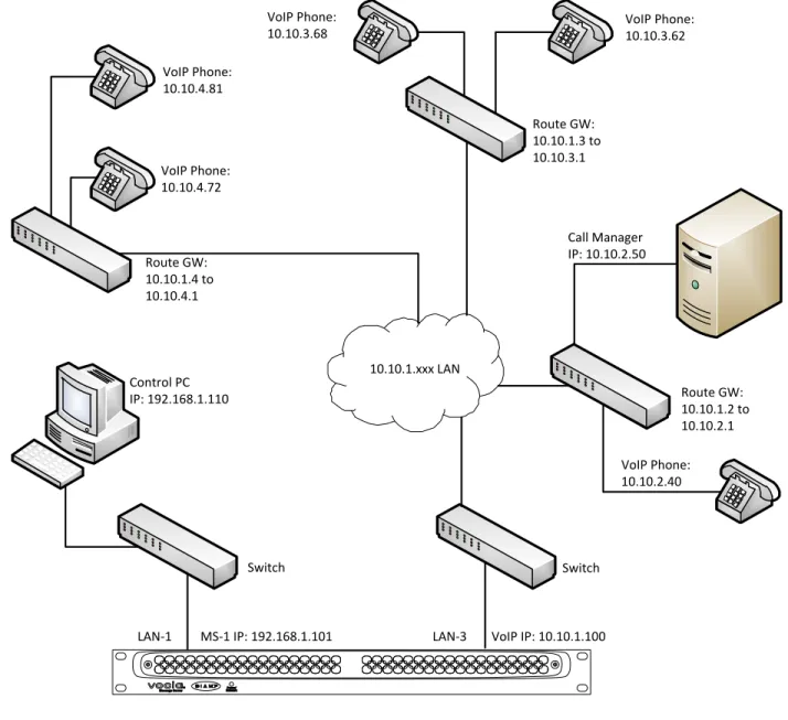
The MS-1 has the ability to specify static VoIP Routes to facilitate connecting multiple gateways with the MS-1 VoIP interface. The following diagram shows a common example where VoIP phones, the Call Manager and the MS-1 are on different networks. In this case there are four gateways employed on the network – 10.10.1.1 (MS-1 default), 10.10.1.2, 10.10.1.3 and 10.10.1.4 . The destination network routes are required to be defined in the MS-1 VoIP Options dialog so that all packets are directed to the default 10.10.1.1 VoIP gateway. Please see figures 5 and 6.
Switch Control PC
IP: 192.168.1.110
Switch
Call Manager IP: 10.10.2.50 Route GW: 10.10.1.3 to 10.10.3.1
Route GW: 10.10.1.4 to 10.10.4.1
VoIP Phone: 10.10.3.62
VoIP Phone: 10.10.4.72
VoIP Phone: 10.10.4.81
VoIP Phone: 10.10.3.68
MS-1 IP: 192.168.1.101 VoIP IP: 10.10.1.100
VoIP Phone: 10.10.2.40
LAN-1 LAN-3
10.10.1.xxx LAN
Route GW: 10.10.1.2 to 10.10.2.1
Figure 5 - Setup for Control and VoIP on different networks with multiple gateways. VoIP routes will be required to allow
In the Vocia software, the MS-1 Properties dialog > VoIP Options dialog allows additional VoIP routes to be specified when multiple gateways are employed. These will determine which networks and devices can reach the MS-1 as well as the communication path to the Call Manager.
Figure 6- VoIP Options dialog with Additional VoIP Routes defined
The first setting in the Additional VoIP Routes dialog (see figure 6) is establishing communication with the 10.10.2.0 Destination Network using the 10.10.1.2 gateway. This would be required to communicate with the Call Manager and would also allow phones on the local 10.10.1.xxx or destination 10.10.2.xxx subnet to reach the MS-1. The Vocia software allows the creation of multiple VoIP routes depending on the needs of the system. The following table gives an example of options available for the diagram shown in figure 6.
Network Subnet Mask Gateway Result
10.10.2.0 255.255.255.0 10.10.1.2 Needed to establish communication with the proxy. All phones in 10.10.2.xxx and 10.10.1.xxx subnet will communicate with the MS-1 10.10.2.0
10.10.4.0
255.255.255.0 255.255.255.0
10.10.1.2 10.10.1.4
Same as above plus all phones in the 10.10.4 subnet will communicate with the MS-1
10.10.2.0 10.10.3.0 10.10.4.0
255.255.255.0 255.255.255.0 255.255.255.0
10.10.1.2 10.10.1.3 10.10.1.4
IP Control and VoIP on the same Subnet
If the Control and VoIP ports are only able to coexist on the same network the MS-1 can be configured so that the Control and VoIP LAN share the same IP and Gateway settings. When configured in this way the LAN-1 port is used and the LAN-3 port is disabled. While supported, this configuration is only to be considered if a small number of VoIP lines are required or there is a physical networking reason limiting the connections to the MS-1. Separating the IP control and VoIP ports as outlined in the previous examples is the preferred connection method. Please refer to figures 7 and 8 below which use the default MS-1 IP address.
LAN-1 IP & VoIP 192.168.1.101 Switch
Call Manager IP: 192.168.1.50 Control PC
IP: 192.168.1.110
( LAN-3 Not Used )
Figure 7 - Setup for VoIP and Control on the same network
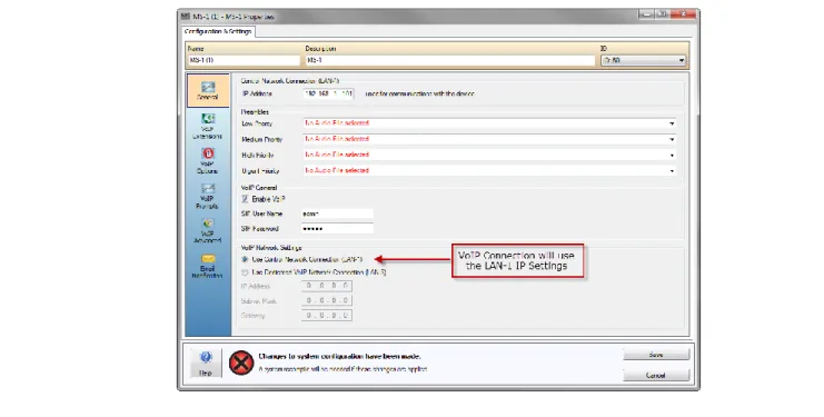
Using the Vocia Software, in the MS-1 Properties dialog > VoIP General section, Enable VoIP and confirm the VoIP Network Settings Radio button is set to Use Control Network Connection (LAN-1).
Figure 8 - IP settings for Control and VoIP on same network
If this application note did not answer your questions on the topic of “Vocia MS-1 Network considerations for VoIP”, please contact