*Corresponding author LIU Ju-bao
Email: [email protected] Tel: +86 1394 6946485 Fax: +86 0459 6507998
Article history
Received: April 15, 2015
Received in revised form: September 19, 2015 Accepted: December 14, 2015
Available online: October 20, 2016
The Analytic Technique and Experimental Research Methods of
Post-buckling about Slender Rod Strings in Wellbore
Yue Qian Bei, Liu Ju‐bao*,andFu Mao‐qing
College Mechanical Science Engineering, Northeast Petroleum University, Hei Long-Jiang, Daqing,China
ABSTRACT
The buckling behavior of rod strings in wellbore is one of the key issues in petroleum engineering. The
slender rod strings in vertical wellbore were selected as research objects. Based on the energy method,
the critical load formulas of sinusoidal and helical buckling were derived for the string with the bottom
of the wellbore pressure. According to the sinusoidal and helical buckling’s geometry of the pressurized
column, the contact friction state of post‐buckling between the rod strings and the wellbore was
considered. This paper adopted Lagrange multiplier method to describe sliding displacement boundary
conditions of wellbore and introduced gravitational potential energy and friction resistance dissipated
energy in the energy method. The contact forces and friction resistances between the rod string and
wellbore were derived in vertical wells. The post buckling experimental apparatus was also developed in
this paper. The sinusoidal and helical buckling critical loads and friction resistances were derived under
different loads. The experimental results are consistent with the theoretical results. Therefore, this
article would provide an effective method for buckling column such as drilling and coiled tubing.
Keywords
: Sinusoidal Buckling, Helical Buckling, Friction Resistance Dissipated Energy, ContactForce, Friction Resistance
INTRODUCTION
The buckling problem of slender rod string within
the wellbore has many adverse effects for
petroleum engineering jobs, particularly in drilling
and workover jobs. Because of the friction forces
surge after bucking the weight of rod string cannot
be added to the drill bit, which will cause the
failure of drill and workover jobs. Thus, it will limit
the application of coiled tubing and the drill depth
for large displacement wells [1, 2]. The buckling
behavior of slender rod string in wellbore has been
a hot topic of concern by researchers at home and
abroad. There are several typical research
methods: the classical differential equation
method [3, 4], the finite element method [5, 6], the
energy method, and so on, among which the
energy method is more used to solve the buckling
problems of rod strings. While in traditional energy
method the gravitational potential energy as well
as friction resistance dissipated energy are not
considered for buckling behavior impact [7‐9], this
paper selects the slender rod strings in vertical
wellbore as the research object. Energy method
based on slender rod strings later buckling behavior
is used to perform research. The formulas of the
critical loads, contact forces, and friction resistances
for sinusoidal and helical buckling are established
for slender rod string in wellbore. The results of this
application of coiled tubing for drilling and
workover jobs and reach horizontal well technology.
(a) Initial position (b) sine (c) helix
Figure 1: The buckling shape of slender rod string in vertical wells.
(a) Initial position (b) sine
(c) Helix
Figure 2: The geometric relationships of buckling for a slender rod string in vertical wells.
The Geometric Relationships of Sinusoidal and Helical Buckling about Slender Rod in Wellbore
In vertical wells, the initial position of the slender rod
is shown in Figure 1 (a). The destabilization of the
string occurs under axial pressure and fluid pressure
of the bottom. The wellbore will lose axial strength
without constraints, and, because of cylinder
constraints, it will make the rod string generate
sinusoidal buckling along cylinder with the increase
of the axial pressure, as shown in Figure 1 (b). When
the axial load continues to increase, the lateral
deformation of the rod string sinusoidal buckling
configuration will increase. When the load reaches
a certain critical value, the buckling configuration of
the string will become helical, and it maintains
continuous contact with the inner wall of cylinder,
as depicted in Figure 1 (c).
According to the geometry of sinusoidal and
helical buckling occurred by a slender rod string
(shown in Figure 2), the geometric relationships
were established in Equations 1 and 2 respectively.
2 s in
0
z
x r
p y
z z
(1)
where x and y stand for the transverse displacement
of the column in the coordinate system; z is the axial
displacement; p is the wavelength of sinusoidal, and r
represents the annular clearance.
c o s s i n 2
x r
y r
z p
(2)
where p is the screw pitch of helical buckling,
and θ is the angle from the initial position of
strings; the rest letters have the same meaning
as in Equation 1.
The following assumptions are used: (1) the
boundary conditions of slender rod string do not wellbore wellbore
wellbore
wellbore
rod string
rod string
rod string rod string
z
z z
y
y
y
y x
x
x
x
F
affect the relationship between force and
wavelength; (2) the deformation of the string is
small; (3) the cross section of the wellbore is circular
and rigid body; (4) the effect of fluid action is not
considered; and (5) the dynamic effects are
neglected.
The Energy Method for Sinusoidal Buckling Critical Load of Slender Rod Column in Vertical Well
When the slender rod string buckling occurs, the
total potential energy includes the bending
deformation energy Ub, the power generated by
bottom hole pressure ΩF, and the gravitational
potential energy W; the related correlation is
shown as follows:
W Ω U
V b F (3)
Assuming
d
is the compression displacementgenerated by bending deformation occurred by dz
part of the rod string, the expression is given by:
' 2 2 2
2 2
( )
1 2
d dz dz dz dz dy dx
dx dy dz dz dz
(4)
Thus the deformation of
dz
section of the rodstring is:
'2 '2
1 2
d x y dz
(5)
For vertical wells, because of y=0, its deformation
for
dz
segment can be expressed as:dz x d 2 2 1
(6)
According to the assumption of small deformation,
the bending deformation energy Ub of the rod
strings is defined by:
2 0 1 2 L b
U
EIx dz(7)
where E is the elastic modulus of the rod string; I
represents the moment of inertia, and L stands
for the total length.
The power of bottom hole pressure is:
L F Fx dz
Ω
0 2
2 1
(8)
The gravitational potential energy W is:
Lwzx dz
W
0 2
2 1
(9)
The first and the second derivatives of x with
respect to z are substituted in the expression of Ub, ΩF, W and through a series of mathematical
integration are shown as follows:
4 2 3 2
4 3
2 2 2 2
2 2 2 2 4 4 sin 4 sin 4
1 4 1 4 1
sin cos
2 4 8 8
b
F
r EIL r EI L
U
p p p
r L r L
Ω F
p p p
r w L L L
W
p p p
(10)
Substitute Equation 10 into Equation 3, the total
potential energy of vertical wells is obtained by:
4 2 3 2 2 2 2
4 3 2
2 2 2 2
4 4 4
sin sin
4
1 4 1 4 1
sin cos
2 4 8 8
r EIL r EI L r L r L
V F
p p p p p p
r w L L L
p p p
(11)
Considering the system energy conservation,
assign V=0, so that
2 2 2 2 2 2 4 4 sin
1sin4 4
1 4 1 4 1
sin cos
2 4 8 8
4 sin 4
b
L L
EI p p
F
L L
p
p p
w L L L
p p p
L L
p p p
2 2 2 EI wL F L
(13)
Assigning 0
p Fb
, then one obtain p=2L;
substituting p into Equation 12, the critical load of
sinusoidal buckling of the rod strings in vertical wells
is shown as follows:
2 2 EI F L
(14)
In the total potential energy, without considering
the gravitational potential energy, the critical load
of sinusoidal buckling is:
If 0
k b k F p
(k=1, 2, 3 …), then one may obtain:
2 2 1 k p L k
(15)
Substituting pk into Equation 12, the K‐order
critical load of sinusoidal buckling is defined by:
2 22
2 1
2 2
k
k EI wL
F
L
,of (k=1, 2, 3 …) (16)
Without considering the gravitational potential
energy, the K‐order critical load of sinusoidal
buckling is given by:
2 22 2 1 2 k k EI F L
,of (k=1, 2, 3 …) (17)
The Energy Method for Helical Buckling Critical Load of Slender Rod Column in Vertical Well
Substituting the first and the second derivatives of
θ into Equation 3, the formula of the total
potential energy is obtained for slender rod string
in helical buckling.
4 2 2 2 0 0 2 2 0 2 2 2 4 2 4 L L b L
E Ir r
V d z F d z
p p
r
w L d z
p
The above equation is simplified to:
4 2 2
2 2 2
2
2 2 2
2 4 b 4
EIr r r
V L F L w L
p p p
(18)
Considering the system energy conservation, the
critical load of helical buckling for strings in
vertical wells is given by:
2 2 2 2 b w L
F E I
p
(19)
The Analysis of Sinusoidal Buckling Contact Force of Slender Rod String in Wellbore
Adopting Lagrange multiplier method, the
contact force and frictional resistance between
string and wellbore are analyzed for sinusoidal
buckling. Considering the gravitational potential
energy and friction resistance dissipated energy,
the total potential energy of the system is
obtained for strings.
f F
b Ω W Ω Ω
U
V (20)
where the expressions of Ub, ΩF, and W are seen in
Equation 10. The
is the contact constraints ofthe wellbore to rod string. The f is the friction
resistance dissipated energy generated by
sinusoidal buckling. The formulas are shown in
Equations 21 and 22 respectively.
‐
0
,
L
g x y dz
(21)where
is the contact force between string andwellbore per unit length; g(x,y) x2 y2 r
is constraint function.
2 2 0 1 [( ) ( ) ] 2 L
f f z x y dz
(22)where, f is the friction coefficient between string
and the wellbore.
energy of system can be expressed as:
0 ( , , , ) 0 ( , )
L L
m
V
f z x x x dz
g x y dz (23)where the first term is the sum of potential
energy and friction resistance dissipated energy,
which can be expressed as:
2
2
2
2, , ,
2 2 2 2
EI F wz fz
f z x x x x x x x
Taking Equation 23 into a step variation:
2 2
0[ ( ) ( ) ]
l m
df d df d df g
V xdz
dx dz dx dz dx x
(24)According to the principle of minimum potential
energy we have
V
m
0
, so the governingdifferential equations of pipe string are expressed
as follows:
2
2
( ) ( ) 0
df d df d df g
dx dz dx dz dx x
(25)
Substitute the derivatives of function f with respect
to x and z into Equation 25,one may obtain:
2
02
EIx
dz d x fz x wz x F dz d (26)
Having substituted the first two derivatives of x
with respect to z into the above equation, the
formula of contact force per unit length is obtained
in vertical wells for strings with sinusoidal buckling.
2
2
4
2
2 2 2
c o s sin
2 2 2
c o s sin 1
2 s in 2
2 2 2
c o s sin 1
w z F w z r z
p p p
f z r f z z
p p p
E I r z
p p
f z r f z z
p p p
(27)
In the calculation of contact force with Lagrange
multiplier method, without considering
gravitational potential energy and friction
resistance dissipated energy, the formula of
contact force per unit length for columns with
sinusoidal buckling in vertical wells is defined by:
2 4
2 sin 2 2 cos 2
F r z EI r z
p p p p
(28)
The Analysis of Helical Buckling Contact Force of Slender Rod Column in Wellbore
In the analysis of helical buckling for slender rod
string, substituting 2pz 、
p
' 2, and
0
''
into Equation 27, the formula of contactforce per unit length for strings with helical
buckling in vertical wells is obtained by:
4 2 2 2 2 2 1
EIr F w z r
p p frz p
(29)
Without considering gravitational potential
energy and friction resistance dissipated energy,
the formula of contact force per unit length of
strings with helical buckling in vertical wells is
expressed as follows:
4 2 2 2 EIr Fr p p
(30)
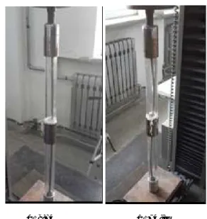
Example Calculation and Experimental Verification
Figure 3: The buckling experimental device of slender string.
Testing machine CMT5105
Axial pressure
The longitudinal strain gauge
Data collected by the strain Organic glass tube Stainless steel
In order to verify the accuracy of the critical load
and friction resistance for sinusoidal and helical
buckling, the bucking indoor tests are designed
for slender column within an organic glass tube.
In this experiment, the stainless steel tube as
the slender rod is used to simulate the pipe
column. The size of the stainless steel tube is as
follows: outer diameter= 6 mm; thickness= 1 mm;
and length= 790 mm. The organic glass tube is
used to simulate the wellbore. The size of the organic
glass tube is as follows: outer diameter= 30 mm;
thickness= 3 mm; and length= 800 mm. An electronic
universal tensile testing machine CMT5105 was
used to provide axial pressure. A dynamic signal
measurement JM5930 was also used to measure
the bottom strain of the organic glass tube at
different axial pressures. The experimental apparatus
is shown in Figure 3.
The Comparison Results of Critical Load with Experimental and Theoretical Calculation of Slender Strings with Buckling
The 1‐10 group specimens of stainless steel tube
were used to carry out a lot of buckling experiments.
The sinusoidal and helical buckling shape occurred
is shown in Figure 4.
(a) sine (b) helix Figure 4: The slender string with helical buckling.
The critical loads of sinusoidal and helical buckling
are obtained for the 10 groups of specimens. At the
same time, Equations 8 and 13 are used to calculate
the critical load. The contrasting results are shown
in Tables 1 and 2 respectively.
Table 1: The comparison result of theoretical and experimental critical load about stainless steel pipe with sinusoidal buckling.
Specimens 1 2 3 4 5
Experimental value (N) 150 160 155 150 150
Theoretical value (N)= 169.5 Deviation (%) ‐11.5 ‐5.6 ‐8.5 ‐11.5 ‐11.5
Specimens 6 7 8 9 10
Experimental value (N) 160 150 160 170 150
Theoretical value (N)= 169.5 Deviation (%) ‐5.6 ‐11.5 ‐5.6 0.3 ‐11.5
Table 2: The comparison result of theoretical and experimental critical load about stainless steel pipe with helical buckling.
Specimens 1 2 3 4 5
Experimental value (N) 1800 1900 1850 2000 1950
Theoretical value (N)= 1945 Deviation (%) 8.1 2.4 5.1 2.8 0.3
Specimens 6 7 8 9 10
Experimental value (N) 1925 1950 2000 1800 1950
Journal of Petroleum Science and Technology 2016, 6(2), 22‐29 http://jpst.ripi.ir
From Table 1, the energy method is used to
calculate the critical load for stainless steel pipe
in this article. When considering the power
applied by gravity, the critical load of sinusoidal
buckling is 169.5 N. Without considering it, the
value is 169.2 N. The difference between two
results is very small. Therefore, the influence of
gravity can be ignored in the calculation of
critical buckling load. As can be seen in the
above table,the error in the theoretical and
experimental critical load is less than 15% in 10
specimens with sinusoidal buckling. From Table 2,
the error in the theoretical and experimental
critical load is less than 10% in 10 specimens
with helical buckling.
The Comparison Results of Friction Resistance with Experimental and Theoretical Calculation for Slender Columns with Buckling
In this paper, the frictional resistances are
calculated for 1‐10 group specimens with
sinusoidal and helical buckling. The values are
compared with the experimental values. The
results are shown in Tables 3 and 4 respectively.
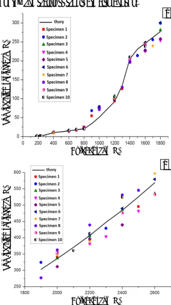
The contrast curve is shown in Figure 5.
From Table 3, Table 4, and Figure 5 (a), the
measurement point for sinusoidal buckling is 92
in 10 group specimens of stainless steel. For 90
points, the error is less than 15%. The error in
only two measuring points is greater than 20%.
It is obvious from Table 3, Table 4, and Figure 5
(b) that the measurement points for helical
buckling is 36 in 10 group specimens of stainless
steel. The error in all measuring points is less
than 10%. The experimental and theoretical
values coincide with each other. To sum up,
Equations 21 and 23 can describe the friction
resistance value for the slender rod string with
sinusoidal and helical buckling well.
In order to compare the impact of gravitational
potential energy and friction resistance dissipated
energy, the stainless steels are also chosen.
Figure 5: The comparison curve of theoretical and experimental frictional force about stainless steel pipe with helical buckling; (a) sine, (b) helix.
An axial pressure of 1.5 kN was applied to the
bottom of the string. The coefficient is 0.5
between the stainless steel pipe and the organic
glass tube. The stainless steel tubes with the
length of 10 m, 20 m, 30 m, 40 m, 50 m, 70 m, and
100 m are calculated respectively. The calculation
results are shown in Table 5.
As it can be seen from Table 5, when the gravitational
potential energy and friction resistance dissipated
energy are considered, the friction resistance value
gradually increases with the length of pipe, and its
value increased from 1.82 kN to 32.03 kN. While the
The
fractio
n
re
sista
n
ce
(N
)
The
fractio
n
re
sista
n
ce
(N
)
Axial Forces (N) Axial Forces (N)
a
gravitational potential energy and friction resistance
dissipated energy are neglected, the trend of
friction resistance value is the same, but its value
increased from 1.75 kN to 18.53 kN. Thus, the
friction resistance values increase rapidly when
one considers gravitational potential energy and
friction resistance dissipated energy. Therefore,
the gravitational potential energy and friction
resistance dissipated energy must be taken into
account in the calculation of friction resistance for
slender rod string in wellbore.
CONCLUSIONS
According to the results obtained the following
conclusions can be drawn:
1.The slender rod string is selected as a research
object in vertical wells. The critical load of sinusoidal
buckling and helical buckling with bottom hole
pressure was derived based on the energy method.
2.According to the geometry of sinusoidal and
helical buckling, the gravitational potential energy
and friction damping dissipation were introduced in
Lagrange multiplier method. The calculation
method of contact force and friction resistance was
established for slender rod string in the article.
3.Aiming the problem of sinusoidal and helical
buckling, the specialized experimental device was
developed for column buckling. The change rules of
sinusoidal and helical buckling were obtained for
columns under different loads, and the theoretical
results coincided with the theoretical ones.
ACKNOWLEDGMENTS
This work was supported by the specialized research
fund for the doctoral program of higher education
(20132322110003) and the project of national
science fund (11272085).
REFERENCES
[1] Tan M. L., Gan L. F., and Wang X. W.,
“Nonlinear Helical Buckling of Drill‐ Strings in
Inclined Wellbore,” Engineering Mechanics,
2007, 24, 199‐202.
[2] Mitchell R. F., “Buckling of tubing inside
casing,” SPE 150613, IADC/SPE Drilling
Conference and Exhibition, San Diego,
California, USA, 2012, 1‐13.
[3] Xiu‐gen W., Bai‐lin Z., and Peng‐fei H., “Study
on Post‐buckling of Constrained Bar,” Journal
of Tongji University (Natural Science), 2009,
37, 26‐31.
[4] Gao G. and Miska S., “Effects of Friction on
Post‐buckling Behavior and Axial Load
Transfer in a Horizontal Well,” SPF Journal,
SPE 120084, 2010, 15, 1104‐1118.
[5] Gao G. and Di Q., Miska S., “Stability Analysis
of Pipe with Connectors in Horizontal Wells,”
SPF Journal SPE 146959, 2012, 17, 931‐941.
[6] Jubao L., Xiuwen W., and Qianbei Y., “The
Buckling Deformation and Contact with Inner
Rod and Outer Casing for Compressional
Tubing,” Mechanics in Engineering, 2011, 33,
25‐29.
[7] Tan M. and Gan L., “Equilibrium Equations
for Nonlinear Buckling Analysis of Drill‐
strings in 3D Curved Wellbores,” Science in
China Series E: Technological Sciences, 2009,
52, 590‐595.
[8] Mitchell R. F., “Tubing Buckling: the State of
The Art,” SPE Drilling & Completion, SPE
104267, 2008, 23, 361 ‐ 370.
[9] Mitchell R. F. and Weltzin T., “Lateral
Buckling: the Key to Lockup,” SPE 139824,