DEVELOPMENT AND PRECLINICAL EVALUATION OF A COMPACT IMAGE-GUIDED MICROBEAM RADIATION THERAPY SYSTEM
Lei Zhang
A dissertation submitted to the faculty at the University of North Carolina at Chapel Hill in partial fulfillment of the requirements for the degree of Doctor of Philosophy in the
Department of Applied Physical Sciences.
Chapel Hill 2016
ii © 2016 Lei Zhang
iii
ABSTRACT
LEI ZHANG: Development and Preclinical Evaluation of a Compact Image-guided Microbeam Radiation Therapy System
(Under the direction of Otto Zhou)
Microbeam radiation therapy (MRT) is a novel and experimental cancer treatment modality. It has received increasing emphasis worldwide in recent years due to the demonstrated high therapeutic ratio in preclinical studies. MRT uses arrays of quasi-parallel radiation beams that are up to a few hundred microns wide and separated by several times of its beamwidth. Extensive preclinical experiments conducted at European Synchrotron Radiation Facility and several other national synchrotron facilities have shown that microbeams with doses of several hundreds of grays are well tolerated by healthy brain tissues while causing preferential damage in tumors. As the effort now moves towards large animal and clinical trials, there are eminent needs to develop compact and economically-viable microbeam irradiators for MRT radiobiology research and clinical installation eventually.
iv
the CNT source array technology. The unique nature of CNT X-ray cathode allows for optimization of the anode focal spot shape and size, and therefore overcomes the obstacles of producing high flux microbeam radiation with conventional X-ray tubes. Preliminary studies have shown that the CNT-based MRT prototype is capable of generating orthovoltage radiation with all essential dosimetric characteristics of microbeam radiation therapy. The goals of this dissertation are to characterize and to optimize the system performance, to implement image guidance for dose delivery, and to evaluate the treatment efficacy in preclinical studies.
Characterization of radiation source and dosimetric parameters was performed and described in detail. An on-board imaging system was constructed and integrated with the microbeam irradiating system. Dedicated image-guidance protocols were developed for high accuracy microbeam delivery in small animal models. Therapeutic assessment of brain tumor bearing mice was conducted with the CNT-MRT prototype. Preliminary results included encouraging treatment effects in terms of tumor local control and mean survival time extension. MRT radiobiological evaluations were carried out, for the first time, using a non-synchrotron-based compact radiation source. Additionally, feasibility of delivering multi-arrays of microbeams cross-firing geometry at the brain tumor target was successfully demonstrated facilitated by multi-modality 3D image guidance.
v
vii
ACKNOWLEDGEMENTS
First and foremost, I would like to express my sincere gratitude to my advisor, Dr. Otto Zhou, for his guidance through my graduate studies. He is truly a great mentor and has inspired me in so many ways in my professional growth. His insights, expertise, and
dedication to research and the advancement of medical technologies have been a great source of motivation through these years. It has been a privilege to work with him and conduct research under his supervision. I would like to thank Dr. Jianping Lu for his direction and help in addressing the challenges and obstacles in completing this work. Beyond that, I must thank both Dr. Lu and Dr. Zhou for their kindness and patience in helping me build up confidence. I’m deeply grateful to Dr. Sha Chang, who has guided me into the field of medical physics. I admire her vision in this field, and every discussion with her was
viii
I would like to thank the amazing members in our group, past and present: Christy Inscoe, Pavel Chtcheprov, Soha Bazyar, Jabari Calliste, Allison Hartman, Gongting Wu, Yueh Lee, Emily Gidcumb, Laurel Burk, Mike Hadsell, Andrew Tucker, Marci Potuzko, Jing Shan, Rachel Ger, Xin Qian, and Sigen Wang. Specially, I must thank Christy who I have been working closely on this project for the past three years. She has been so kind and supportive, and has taught me so many things over these years. This work would not have been completed without her. Thanks to all my friends for being here while I’m here, during joyful moments and struggling time. They all have made these years so much more colorful.
This project was funded through the National Cancer Institute and the Carolina Center of Cancer Nanotechnology Excellence. I would also like to thank the generous support from the Royster Society of Fellows and The Ross and Charlotte Johnson Family Dissertation Fellowship in completing this thesis.
Last but not least, I thank my dearest parents. They are the greatest source of
motivation and support throughout years of education. Thanks for teaching me to be grateful for what I have been given, and for teaching me to make dreams come true through my own efforts. I’m proud to be the daughter of yours.
ix
x
TABLE OF CONTENTS
LIST OF TABLES ... XV LIST OF FIGURES ... XVI LIST OF ABBREVIATIONS ... XXV
INTRODUCTION ... 1
CHAPTER 1: Radiotherapy for Cancer Management ... 1
1.1 Microbeam Radiation Therapy – Roots, Status, and Prospects ... 5
1.2 History and inspiration ... 5
1.2.1 Synchrotron-based microbeam radiation therapy ... 8
1.2.2 Experimental characteristics ... 8
1.2.2.1 Biological features ... 11
1.2.2.2 Overview ... 11
Bystander effects ... 13
Vasculature responses ... 14
Compact microbeam delivery systems – challenges and efforts ... 16
1.2.3 The Scope of This Work ... 17
1.3 References ... 20
CARBON NANOTUBE FIELD EMISSION SOURCE ARRAYS ... 28
CHAPTER 2: Overview ... 28
2.1 Structures and Physical Properties of Carbon Nanotubes ... 28
xi
Fundamentals of field emission theory ... 30 2.3.1
Carbon nanotubes as field emitters ... 33 2.3.2
Carbon nanotube field emission X-ray technology ... 35 2.3.3
Carbon nanotube source array based medical devices ... 37 2.3.4
Diagnostic imaging devices ... 38 2.3.4.1
Radiotherapy systems for preclinical studies ... 45 2.3.4.2
Cellular irradiator and multi-pixel micro-radiotherapy system ... 45 Image-guided microbeam radiation therapy system ... 45 References ... 47
DEVELPING A COMPACT MICROBEAM IRRADIATOR USING THE CHAPTER 3:
CARBON NANOTUBE FIELD EMISSION SOURCE ARRAY ... 52 Overview ... 52 3.1
The First-generation Prototype ... 55 3.2
Main components ... 56 3.2.1
Source characteristics... 60 3.2.2
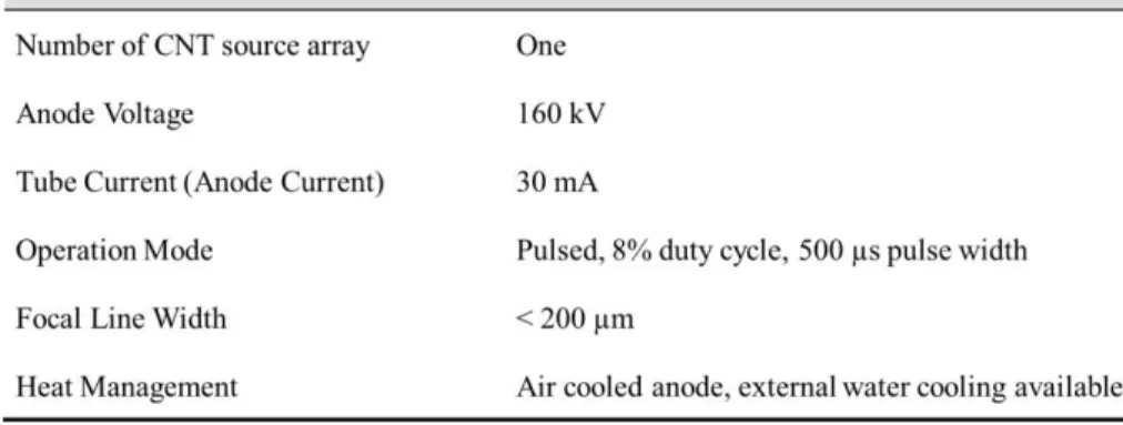
Tube specifications in standard mode of operation (full power) ... 61 3.2.2.1
Photon energy spectrum ... 62 3.2.2.2
Focal line size ... 62 3.2.2.3
Dosimetric Characteristics ... 63 3.3
Film dosimetry with Gafchromic EBT2/EBT3 films ... 64 3.3.1
Half value layer (HVL) ... 69 3.3.2
Dose rate ... 71 3.3.3
Distance correction ... 72 3.3.4
xii
Tissue maximum ratio (TMR) ... 76 3.3.6
Challenges and Remedies ... 79 3.4
Microbeam collimator alignment ... 79 3.4.1
Anode rotation ... 84 3.4.2
References ... 89 IMAGE GUIDANCE FOR MICROBEAM RADIATION THERAPY ... 91 CHAPTER 4:
Motivation ... 91 4.1
Implementing Image Guidance for Microbeam Delivery ... 92 4.2
Construction of the imaging system ... 92 4.2.1
Integration of the IGMRT system ... 95 4.2.2
Design of the animal positioning device ... 96 4.2.3
Peripheral components ... 99 4.2.4
System calibration and testing ... 100 4.2.5
References ... 101 IMAGE-GUIDED MICROBEAM DELIVERY IN SMALL ANIMALS ... 102 CHAPTER 5:
Motivation ... 102 5.1
Delivery of Single Array Microbeams in Mouse Brain with 2D Image Guidance .. 104 5.2
Methods... 104 5.2.1
Tumor cell and animal preparation ... 105 5.2.1.1
Imaging and beam planning ... 106 5.2.1.2
Image processing and registration ... 108 5.2.1.3
Microbeam alignment and irradiation ... 109 5.2.1.4
Beam verification using immunohistological staining ... 111 5.2.1.5
xiii
Dose verification ... 112 5.2.2.1
Immunohistological staining ... 114 5.2.2.2
Discussion ... 116 5.2.3
Multi-array Microbeam Irradiation in Brain Tumor Bearing Mice ... 119 5.3
Upgrade in animal positioning device ... 120 5.3.1
Image guidance protocols ... 123 5.3.2
Two-view planar image guidance with 2D image registration ... 123 5.3.2.1
MRI/CT guidance with 3D image registration ... 126 5.3.2.2
References ... 134 PRECLINICAL EVALUATION OF MRT THERAPEUTIC EFFICACY USING CHAPTER 6:
THE COMPACT IRRADIATOR ... 136 Introduction ... 136 6.1
Methods and Materials ... 137 6.2
Brain tumor bearing mouse model ... 137 6.2.1
Image guidance ... 138 6.2.2
Unidirectional microbeam array ... 138 6.2.2.1
Crossbeam MRT ... 139 6.2.2.2
Radiation treatment ... 139 6.2.3
Microbeam radiation therapy ... 139 6.2.3.1
Broad-beam radiation treatment ... 140 6.2.3.2
Survival & statistical analysis ... 141 6.2.4
Immunohistological analysis ... 141 6.2.5
Characterize DNA damage with γ-H2AX staining ... 143 6.2.5.1
xiv
Characterize cell proliferation using Ki-67 immunofluorescence staining 144 6.2.5.3
Results ... 144 6.3
Verification of dose delivery ... 144 6.3.1
Microbeam effects on the mean survival time ... 146 6.3.2
Microbeam effects on tumor local control ... 146 6.3.3
Microbeam radiation induced DNA damage and its dynamics ... 148 6.3.4
Microbeam effects on apoptosis and cell proliferation ... 149 6.3.5
Preliminary results with MRT delivered in orthogonal arrays ... 154 6.3.6
Discussion ... 155 6.4
References ... 161 CONCLUSIONS AND PROSPECTS ... 163 CHAPTER 7:
Summary of This Work ... 163 7.1
High-power Compact MRT System ... 165 7.2
The second-generation prototype ... 165 7.2.1
Design for human MRT with multiple beam arrays ... 166 7.2.2
Future Directions ... 167 7.3
xv
LIST OF TABLES
Table 2.1 Selected physical properties of carbon nanotubes [3, 6] ... 30 Table 3.1 Selected parameters for full power operation of the first CNT-MRT prototype ... 61 Table 4.1 Characteristics of the three cathodes in the micro-focused tube of the CT scanner ... 93 Table 5.1 A flow chart illustrating the procedure of multi-modality image-guided microbeam radiation therapy in brain tumor bearing mouse models. ... 105 Table 5.2 Summary of the uncertainties in beam targeting using the 2D image-guided MRT protocol. Pictures are reprinted with permission from Zhang et al. Physics in Medicine and Biology 59, 1283-1303 (2014) [1]. ... 116
Table 5.3 Summary of the results from the MRI/CT image guided MRT
delivered in orthogonal arrays. ... 130 Table 6.1 Summary of the biological studies carried out with the CNT-MRT system ... 137 Table 7.1 Comparison of the system specifications of the first and second generation
xvi
LIST OF FIGURES
Figure 1.1 The radiation biology flow chart (Lecture handout for Radiation biology at UNC Chapel Hill. Reprinted with permission from Dr. Elaine Zeman, UNC Department of Radiation Oncology) ... 2 Figure 1.2 Histopathologic evidence of different radiobiological effects caused by microscopic versus millimeter-sized deuteron beam on the visual cortex of the mouse brain, which is a direct proof of the dose-volume effect. Adapted from Zeman W. et al.,
Radiation Research 15, 4 (1961) ... 7 Figure 1.3 A photo of the sample positioning stage in the MRT experiment room at
ESRF Biomedical Beamline ID17 ... 10 Figure 2.1 Electronic density of states for two zigzag carbon nanotubes, a metallic (9, 0) one on the left, and a semiconducting (10, 0) one on the right. Reprinted from Saito et al. Applied Physics Letters 60(18), 1992 [5] ... 30 Figure 2.2 A schematic illustration of the potential energy of electron U(x) (in eV) as a function of the distance x from the metal surface in an external static electric field. The effective energy barrier is sufficiently narrowed that the electrons could tunnel through. Horizontal dotted line illustrates the energy barrier width for electrons at Fermi level to tunnel through. ... 31 Figure 2.3 The configuration of an X-ray tube with the CNT field emission cathode. G represents the gate mesh where the electrostatic potential is applied for electron extraction. F1 and F2 are focusing electrodes for customizing the shape of the electron beam as well as the resultant focal spot on the anode. High voltages (kV) are applied between the cathode and anode for electron acceleration and X-ray generation. All parts are sealed inside an evacuated housing with a thin layer of window material as X-ray exit port. Electronic control circuit is now shown here for simplicity purpose. ... 36 Figure 2.4 A schematic illustration (left) of a multi-beam x-ray source with five individually controlled CNT emitting pixels [53]; and examples of CNT-based X-ray tubes with multiple sources and in linear (middle) or square (right) geometries,
xvii
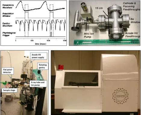
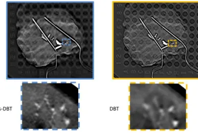
Selenia Dimensions scanner; right: a photo of the s-DBT prototype installed at North Carolina Cancer Hospital (Chapel Hill, NC) for clinical trial [68]. ... 42 Figure 2.7 Comparison of the reconstructed images from s-DBT and DBT in human specimen study. Photos adapted from Tucker et al. Proc. of SPIE Vol. 9033, 903316
Medical Imaging 2014 [70] ... 43 Figure 2.8 The s-DCT prototype installed at the Cystic Fibrosis and Pulmonary Diseases
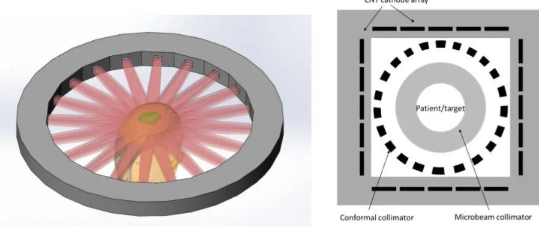
Research and Treatment Center, at UNC Marsico Lung Institute for clinical trials... 44 Figure 3.1 Schematic drawing illustrating the difference of point focus and line-focusing X-ray sources, the microbeam collimator needed for each source, and the resultant dose profiles. ... 52 Figure 3.2 Schematic drawings of the design concept of compact high-flux microbeam delivery systems with multiple arrays of CNT generated microbeams arranged in a ring (left) or a square (right) configuration around the target to achieve dose conformality physically. Customized MRT treatment can be delivered by electronically programming the on-and-off status of
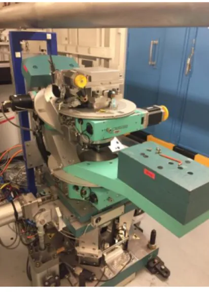
individual cathode segments. ... 54 Figure 3.3 A photograph of the CNT-MRT first prototype constructed on an optical table inside a shielded enclosure in our lab at UNC Chapel Hill. Some of the main external components are indicated. Secondary shielding panels are also installed surrounding the MRT tube on the optical table during operation. As can be seen, a CNT-based micro-CT scanner is built on the same optical table to provide image guidance. ... 55 Figure 3.4 Illustration of the main components of the CNT-MRT system including the photon production structures enclosed in the vacuum chamber, and the microbeam collimator
underneath the X-ray window. ... 56 Figure 3.5 Top left: a photograph of the CNT cathode. The area in black is the deposited layer of CNT emitters. Top right: SolidWorks drawings (trimetric view) of the cathode assembly. Bottom: cross-sectional view. Main structures are labeled, including the cathode (CNT emitters deposited on molybdenum substrate), gate mesh, and two focusing electrodes. ... 58 Figure 3.6 SolidWorks drawings of the microbeam collimator assembly. ... 60 Figure 3.7 The measured photon energy spectrum measured using AmpTek XR-100T-CeTd X-ray detector (top), and the simulated spectrum using SpekCalc (bottom). ... 63 Figure 3.8 Illustration of the different layer configurations of
Gafchromic EBT2 (left) and EBT3 (right) films [13]. ... 65 Figure 3.9 Top: Illustration of the side-by-side setup of EBT3 film and an ion chamber in the cross-calibration process. A piece of EBT3 film was placed between two thin layers of plastic, with the plane of EBT3 film aligned with the central plane of the ion chamber. Bottom:
Illustration of the sectional view of an ion chamber,
xviii
xix
parallel position with respect to the focal line on the anode, as shown on the left. The one on the right indicates a parallel-aligned slit and focal track. Middle row: images acquired by the
detector shown in ImageJ. Bottom row: illustrations of the relative locations of the collimator slit and the anode focal line when not-aligned (left) and aligned (right) corresponding to the beam profiles as shown in the top and middle row. Dimensions are not drawn to scale. ... 83 Figure 3.22 Comparison of the beam profiles before (right) and after (left) collimator alignment. Notice the change in the beam shape and peak dose rate. ... 84 Figure 3.23 Left: Non-tilted (in both vertical and horizontal directions) anode as originally installed. Right: the rotated anode with further end from the plane of the paper drifted towards the cathode assembly, while the closer end moved towards the back wall of the chamber. ... 85 Figure 3.24 Left: SolidWorks drawing highlighting the cylinder that connects the anode to the HV feedthrough with two threaded joints on both ends. Right: two setscrews were added
subsequently after the anode rotation was found, to prevent any rotation that might have occurred at the joints on the cylinder from the side towards the back wall of the vacuum chamber. ... 86 Figure 3.25 SolidWorks drawing and a photograph (bottom view) of the anode assembly
highlighting the two setscrews at the bottom of the anode. ... 87 Figure 3.26 Left: original design of the anode assembly. Right: modified
design of the L-bracket to avoid anode rotation. ... 88 Figure 4.1 SolidWorks design of a compact system for micro-CT guided
microbeam radiation therapy. ... 92 Figure 4.2 Left: A photograph of the micro-CT scanner built on the side of the microbeam irradiator, with key components indicated with red arrows. The gantry stands on top of the optical table, facing the back side of the turbo pump on the microbeam irradiator. Right: control console for the micro-CT outside the shielded enclosure. ... 94 Figure 4.3 Illustration of the changes made to the turbo pump support (highlighted in blue color) in the microbeam irradiator, and the extended tube stand. Drawing on the left is the original design, while the one on the right demonstrates the modification. ... 95 Figure 4.4 SolidWorks drawing of the home-made mouse holder. The design includes two parts, i.e. the main body of the holder and a nosecone holder attached on top. [7]. ... 97 Figure 4.5 A photo of a nude mouse positioned on the mouse holder under anesthesia. ... 98 Figure 4.6 SolidWorks drawings of the modified mouse holder for
P12 mouse pups (left); and the double-stage (right). ... 98 Figure 4.7 A photo of the anesthesia setup equipped to the CNT-MRT system
xx
Figure 4.8 A photograph of the CNT-based image-guided microbeam radiation therapy system constructed on an optical table in our lab at the University of North Carolina at Chapel Hill. .. 100 Figure 5.1 Illustration of a single array of microbeams irradiating the mouse brain. The relative locations of target, landmarks, and radiation field are defined by
a Cartesian coordinate system as indicated. ... 104 Figure 5.2 Top row: on the left is a picture of animal immobilized on the customized mouse holder under anesthesia, while on the right is a picture showing the setup of double-mouse imaging. Bottom row: illustrations of two mice imaged by the micro-CT scanner one after the other, in the image-and-shift manner. Pictures are reprinted with permission from Zhang et al. Physics in Medicine and Biology 59, 1283-1303 (2014) [1]. ... 106
Figure 5.3 Left: MR image of the mouse brain with the targeted tumour circled. Middle: X-ray projection of the same animal showing the landmark ear bars and skull features. Right: X-ray projection registered with MR image showing the relative position of the tumour and ear bars. Pictures are reprinted with permission from Zhang et al.
Physics in Medicine and Biology 59, 1283-1303 (2014) [1]. ... 108
Figure 5.4 Diagram showing the geometric relations between the targeted tumor, landmark, and microbeam locations. The z-direction is perpendicular to the paper plane. The microbeam plane is in the y-z plane. Δx1 is the distance from the tumor to the ear bars measured in the registered image, Δx2 is the distance of translation from the MRT chamber to the micro-CT, and Δx3 is the distance between the center of the ear bar and the alignment microbeam track measured during microbeam alignment. The mouse holder with the Gafchromic film was first irradiated for beam alignment, as shown on the left, and then translated to the right, followed by mouse positioning and X-ray imaging. Pictures are reprinted with permission from Zhang et al.
Physics in Medicine and Biology 59, 1283-1303 (2014) [1]. ... 109
xxi
about 280 microns, and 380 microns at the exit plane. The PVDRs recorded for this animal were roughly 16 at the entrance plane, and 15 at the exit plane. Pictures are reprinted with permission from Zhang et al. Physics in Medicine and Biology 59, 1283-1303 (2014) [1]. ... 113 Figure 5.8 Fluorescence images of -H2AX stained mouse brain tissue slices after microbeam irradiation. The -H2AX foci-positive cells, shown as pink strips, correspond to the microbeam pattern. Areas circled in yellow are tumour targets. The images correspond to animal ID 1087 (left) that was treated with two microbeams with 109 Gy/beam, and 1089 (right) which received a single microbeam radiation with 138 Gy entrance dose. In both cases, microbeams were delivered right on target as planned. Pictures are reprinted with permission from Zhang et al. Physics in Medicine and Biology 59, 1283-1303 (2014) [1]. ... 114
Figure 5.9 Comparison of the -H2AX stained mouse brain tissue slices from animal ID 1152 and ID 1149 both treated with three microbeams with 48 Gy/beam entrance dose. As labeled in the images, three planned microbeams were delivered on target for the case on left, while for the one right, two out of the planned three microbeams were delivered off-target. Pictures are reprinted with permission from Zhang et al.
Physics in Medicine and Biology 59, 1283-1303 (2014) [1]. ... 115
Figure 5.10 -H2AX stained, sagittal image registered with MR projection for the same slice of tissue, from two animals (Left: ID 1152 and right: ID 1145) irradiated with three microbeams of 48 Gy/beam. Microbeam tracks are the pink strips through the higher contrast tumour region, demarcated by the yellow circle. The targeting error was measured from the microbeam location to the targeted tumour center. Pictures are reprinted with permission from Zhang et al. Physics in Medicine and Biology 59, 1283-1303 (2014) [1]... 115
Figure 5.11 Illustration of two orthogonal arrays of microbeams
traversing through the mouse brain... 120 Figure 5.12 Photographs of the setup for delivery two perpendicular arrays of microbeams in the cross-beam configuration. A mouse phantom is placed on the mouse holder, and the green lines demonstrate the microbeam entrance location on the mouse head. ... 122 Figure 5.13 SolidWorks drawings of the modified sample stage and mouse holder. The three mounting positions are indicated with dash lines (top right),
xxii
Animal euthanization was performed 4 hours after radiation was
completed for tissue collection and fixation. ... 125 Figure 5.16 Top: screenshot of the user interface of PLUNC, clinical treatment planning software developed at UNC Department of Radiation Oncology. A special edition was installed on the desktop computer for micro-CT operation. Bottom: a screenshot showing 3D registration (sagittal view) of a MR scan and CT scan of a mouse in PLUNC. Soft tissue contrast in MR image (shown in red) and the contrast in bony structures presented in CT (shown in green) can be adjusted individually. Translation and rotation are performed in
three anatomical planes (coronal, sagittal, and axial). ... 127 Figure 5.17 Image registration in three anatomical planes using PLUNC. Tumor target is shown with hyper-intense signal from MR images (in green) with
the center of volume indicated with a cross mark. ... 128 Figure 5.18 Photographs of the new mouse holder designed for crossbeam MRT. A metal bb (Aluminum, 0.79 mm in diameter) is embedded on the ear bar pillar as indicated. The picture on left is from a phantom study to test the reposition consistency of the sample stage, and the picture on right is from U87 bearing mouse irradiated with crossbeam MRT. ... 129 Figure 5.19 γ-H2AX stained tissue slices and the corresponding MR slices from animal ID 1293 (top row) and 1300 (bottom row). Tumor targets are indicated with yellow arrows in the
xxiii
Figure 6.4 A: T2 weighted MR images of the mouse brains before and after different treatment. Tumor targets were contoured with white dash lines. B and C: absolute and relative tumor volumes growth calculated from the MR images. Reprinted with permission from Yuan et al. Radiation Research 184, 322-333 (2015) [3]. ... 147
Figure 6.5 γ-H2AX stained normal mouse brain tissue and brain tumor tissue after microbeam treatment. A: changes of γ-H2AX positive signal at different times post-irradiation. Microbeam paths were clearly distinguishable from the background in both tumor region and normal tissue at 1h and 24h post-irradiation. The beam tracks blurred out in tumor at 48h and 7 days after
radiation, which was not observed in normal tissue in contrast. B and C: quantification of the γ-H2AX expression. The expression decreased over time after treatment, indicating the cell repair process. Reprinted with permission from Yuan et al.
Radiation Research 184, 322-333 (2015) [3]. ... 149
Figure 6.6 Immunofluorescence staining of cleaved caspase-3 as cell apoptosis assay. Cleaved caspase-3 signal is shown in red, while DAPI counterstaining of the nuclei is shown in blue. A and B: Levels of apoptosis in tumor at 1h and 7d after MRT. Reprinted with permission from Yuan et al. Radiation Research 184, 322-333 (2015). ... 150 Figure 6.7 Immunofluorescence staining of Ki-67 on tumor as biomarker for cell proliferation 1h (A) and 48h (B) after MRT. Ki-67 positive cells are shown in red,, while DAPI counterstaining of the nuclei are shown in blue. White arrows indicate the microbeam radiation paths on the tumor. Ratios of proliferation staining to non-irradiated control are plotted (C) over time for both the peak and valley regions. Proliferation rate continuously decreased from 1h to 48 h, but bounced back at day 7 after MRT. Reprinted with permission from Yuan et al.
Radiation Research 184, 322-333 (2015). ... 151
Figure 6.8 Apoptosis in normal mouse brain tissue after MRT. Reprinted with permission from Yuan et al. Radiation Research 184, 322-333 (2015). ... 151 Figure 6.9 Quantification of cell proliferation using Ki-67 immunohistological staining on the contralateral normal mouse brain tissue after MRT and BRT. A significantly higher number of proliferation cells were found in the MRT treated mice, but not in the BRT treated mice at 24h or 48h post-irradiation (* P <0.05, compared to BRT). Reprinted with permission from Yuan et al. Radiation Research 184, 322-333 (2015). ... 152
Figure 6.10 F4/80 immunostaining on normal mouse bran tissue at 24 hours and 30 days after MRT. No positively stained macrophages or microglia cells were found at either time point. No other morphological brain tissue damage was detected. Reprinted with permission from Yuan et al. Radiation Research 184, 322-333 (2015). ... 153
Figure 6.11 Tumor progression monitored by MRI following different treatments. Tumor volume was shown as relative to the volume one day prior to treatment. Adapted from Zhang et al. in Expert Review of Anticancer Therapy 14 (12), 1411 – 1418 (2014) [4]. ... 154
xxiv
width can be generated simultaneously. Bottom row: a photograph of the three-line cathode assembly is shown on left; on right shows a photograph of the vacuum chamber of the second-generation system... 166 Figure 7.2 Schematic illustration of the CNT-based human MRT system in a circular design. Microbeam are generated from distributed CNT source arrays from multiple directions and directed towards the treatment target simultaneously. Each beam array contains multiple
xxv
LIST OF ABBREVIATIONS
BNL Brookhaven National Laboratory BRIC Biomedical Research Imaging Center
BRT Broad-beam radiation treatment / Broad-beam radiation therapy
CLS Canadian light source
CNT Carbon nanotubes
COST Cooperation in Science and Technology
CT Computed tomography
CTV Clinical target volume C-T-C Center-to-center
DNA Deoxyribonucleic acid
DR Dose rate
EBL Electron beam lithography
ECG Electrocardiogram
EPD Electrophoretic deposition
ESRF European Synchrotron Radiation Facility
FE Field emission
FED Field emission display
FNTD Fluorescence nuclear track detector
FWHM Full-width-at-half maximum
GBM Glioblastoma multiforme
GJIC Gap junction intercellular communication
xxvi
HVL Half value layer
ICS Inverse Compton Scattering
IGMRT Image-guided microbeam radiation therapy IGRT Image-guided radiation therapy
IMRT Intensity-modulated radiation therapy
LINAC Linear Accelerators
MRI Magnetic resonance imaging MRT Microbeam radiation therapy
MST Median survival time
MTF Modulation Transfer Function
MWNT Multi-walled carbon nanotube
NSLS National Synchrotron Light Source PASS Patient Safety System
PDD Percentage depth dose
PVDR Peak-to-valley-dose-ratio
RGA Residual gas analyzer
RIBE Radiation-induced bystander effect
RT Radiation therapy
s-DBT Stationary digital breast tomosynthesis s-DCT Stationary digital chest tomosynthesis s-IOT Stationary intra-oral digital tomosynthesis SEM Standard error of the mean
xxvii SRT Stereotactic radiotherapy
SR Synchrotron radiation
SS Specific Surfaces
SWNT Single-walled carbon nanotube
TMR Tissue maximum ratio
TPL Translational Pathology Lab
TPR Tissue phantom ratio
TR Transmission rate
1
INTRODUCTION CHAPTER 1:
Radiotherapy for Cancer Management
1.1
The human body is a complicated ecosystem whose individual members are cells that are organized into collaborative assemblies of tissues. Its integrity and stability are synergetic effects of “regulatory systems” composed of hierarchical components, from the chromosome in an individual cell to the whole body immune regulations. Only certain types of cells have the capability of dividing and proliferating, and errors occur during these processes due to internal instability or environmental influences. Some of the errors are fatal to the cells, and some can be reinstituted by the gene repair mechanisms. The failure of proper repair of deoxyribonucleic acid (DNA) damage often results in cell death in most cases and mutagenesis that could lead to
innocuous cell survival. Very rarely malignancies occur if mutated cells escape the restraints of replicative senescence and the guard of the human immune system, and persist to divide, invade and colonize territories normally reserved for other cells (Figure 1.1). About 90% of human cancers are carcinomas, perhaps because most of the cell proliferation in the body occurs in epithelia, or because epithelial tissues are most frequently exposed to the external damages that stimulated the form of cancer [1].
2
usually takes years. Clinical data have shown clearly that for most cancers the treatment outcome is significantly better when the cancers are diagnosed at earlier than late stages. The limited capability of available technologies today to detect early stage, small, in situ tumors is the main challenge in cancer management, and the main cause of the high mortality.
Figure 1.1 The radiation biology flow chart (Lecture handout for Radiation biology at UNC Chapel Hill. Reprinted with permission from Dr. Elaine Zeman, UNC Department of Radiation Oncology)
3
damage compared to those in the normal tissue. This opens up the therapeutic window in radiation therapy. However, the amount of the radiation dose and the treatment volume required for complete tumor cell sterilization often unavoidably lead to radiation dose to nearby normal structure that exceeds their tolerance, and hence increases the risk of severe normal tissue
complications. Radiation-induced normal tissue complications remain as the major concern and a great challenge in RT. The risk of serious damage in normal tissue increases with radiation dose, as does the probability of local tumor control. The rapid rate of tumor regeneration and
metastasis further complicates the treatment strategy. Improving the therapeutic ratio, i.e. maximizing the local or locoregional tumor control by permanently inactivating all cancer cells while minimizing the normal tissue damage, is the goal in radiotherapy [3]. In the last decade, new technologies in image guidance, treatment planning, as well as dose delivery have
developed greatly and contributed substantially to the optimization in the clinical practice and treatment outcome of radiation therapy. One main way to improve the therapeutic efficacy is to achieve physical dose conformality in the clinical target volume (CTV) discerned by image guidance and decrease the volume of normal tissue irradiated and therefore the probability of normal tissue complications. In terms of external beam radiation therapy for instance, 3D
4
procedure is called SRT if multiple dose fractions are delivered. A high degree of dose conformity is a hallmark of SRS, which is generally achieved by using appropriate circular beams to fit the lesion, optimizing arc angles and weights and using multiple isocenters or dynamically shaping the field during arc rotation with mini (or micro) multileaf collimators [4].
The effectiveness of tumor control using radiation therapy, as well as with other types of cancer treatments is not completely known yet. The treatment outcome is often largely dependent on various factors including the type of the cancer, the stage and progression, and the sites of the malignancies etc. Malignant brain cancer is one of the most aggressive cancers nowadays with minimum breakthrough made in terms of extending the patients lifespan using modern treatment technologies. The risk of losing major neurological functions often limits the extent and effect of surgical resection. Chemotherapy alone is often not effective for brain cancer management due to the blood-brain barrier which prevents a high dose uptake in the brain tumor. Radiation therapy plays an important role in the curative and palliative treatment of patients with primary and metastatic brain tumors. Existing SRS techniques including CyberKnife and Gamma Knife are able to achieve effective tumor control with minimum treatment toxicity for small lesions (<3 cm in diameter) at non-eloquent areas. The field size of gamma knife is limited to a maximum of 18 mm in diameter [4]. However, glioblastoma multiforme (GBM), the most common and
malignant brain tumor, is highly aggressive and infiltrative in nature. These tumor cells are fast proliferating and tend to invade into the surrounding normal tissue, rendering a large and not well-defined lesion site surrounded by critical brain structures. The clinical target volume needs to be typically large in order to completely sterilize the primary tumor mass as well as the cancer cells that interdigitate with the surrounding normal brain tissue. For these reasons, severe
5
technologies, and tumor recurrence at the primary site happens in 90% of the cases [5]. The acute and late effects of RT on the brain are common and represent a significant source of morbidity. Primary brain cancer is also the second most prevalent cancer type in children, accounting for 22% of tumors in those < 18 years of age [6]. Radiation toxicity is even more of an issue for pediatric brain tumor patients as their developing central nervous system tissues can be more sensitive to chronic radiation damage. Over the last 50 years the survival extension has improved minimally for brain cancer patients. The median survival time in those with GBM is merely 15 months after diagnosis even when aggressive multi-modality treatments are applied [5, 7, 8].
Microbeam Radiation Therapy – Roots, Status, and Prospects
1.2
History and inspiration
1.2.1
6
normal cells that acted as the healing centers around the irradiated areas. This method was later recognized as spatially fractionated radiation therapy, or more commonly known as GRID therapy, and was routinely performed in orthovoltage beam RT in the 1950s to avoid prohibitive skin and subcutaneous tissue toxicity when treating deep-seated tumors [12, 13]. Nowadays, the advantage of GRID therapy has been largely overshadowed by the widely employed
megavoltage beams RT with linear accelerators which achieve natural dose buildup underneath the skin entrance and deep penetration to reach internal tumors. GRID is mainly utilized as a palliative treatment for advanced bulky tumors using LINAC with new development in the grid design in recent years [14-16]. GRID therapy represents the very first successful clinical
adaptation of the later formulated radiation dose-volume effect in the form of
spatial-fractionation. The dose-volume effect describes the inverse relationship between the threshold of tolerable radiation dose in normal tissue and the irradiated macroscopic tissue volume [17]. As a common radiotherapeutic perception today, the radiation dose-volume effect is established based on accumulating preclinical and clinical experience, and has guided the development of modern radiotherapy in many ways [18, 19].
7
were largely preserved; neither was there permanent damage to the vessels. It was assumed then that the microscopic radiation beams only caused localized and predominantly direct injuries without much additional indirect effect such as interference with blood supply as seen in the broader beam irradiations. These encouraging findings correlated well with the macroscopic radiation dose-volume effect [17], but also led to the further exploration of using microbeam radiation for brain cancer treatment starting in the 1990s at both BNL National Synchrotron Light Source (NSLS) in Upton, New York and the European Synchrotron Radiation Facility (ESRF) in Grenoble, France [25-29].
Figure 1.2 Histopathologic evidence of different radiobiological effects caused by microscopic versus millimeter-sized deuteron beam on the visual cortex of the mouse brain, which is a direct proof of the dose-volume effect. Adapted from Zeman W. et al.,
Radiation Research 15, 4 (1961)
As originally proposed, MRT refers to an experimental treatment technique which
employs arrays of quasi-parallel, microscopically thin planar X-ray beams that are separated by a distance several times the beamwidth. Several features stand out in MRT compared to
8
alternating peaks (high dose) regions and valleys (low dose) regions with a signature index named the peak-to-valley-dose-ratios, or PVDR [25, 29]. The total prescribed dose is usually delivered in a single fraction, either from one direction, or multiple ports around the target. The synchrotron generated microbeams are also featured by their ultra-high flux and minimal divergence. As shown in numerous preclinical studies using duck embryos, mice, rats and weanling piglets, MRT allows for administration of a single radiation dose that is two orders of magnitude higher than the total dose delivered in temporal fractionated RT from LINAC in the CTV without causing severe functional damage in normal tissue [26, 28, 35-47]. While existing RT technologies strive to achieve physically localized dose deposition for an optimal therapeutic ratio, MRT provides an alternative with the intrinsic differential radiobiological effects on tumor versus on normal brain tissue.
Synchrotron-based microbeam radiation therapy
1.2.2
Experimental characteristics
1.2.2.1
The original pilot experiments, as well as the majority of MRT preclinical studies in the last two decades were carried out at the NSLS and ESRF. Particularly, the ESRF Biomedical Beamline ID17 is currently the major beamline for MRT biological studies, veterinary trials and the clinical trials that are under preparation [48]. In recent years, increasing efforts have also been made in instrumentation upgrades and development to incorporate MRT studies at several other beamlines worldwide, including the Canadian Light Source (CLS) [49-52], the SPring-8 synchrotron radiation facility in Japan [53, 54], and the Australian Synchrotron facility [55]. As a powerful and valuable tool for a wide variety of research, synchrotron radiation differs
9
storage ring. The high-energy beam is then directed through strong magnetic fields generated by bending magnets or insertion devices (undulators or wigglers). The applied magnetic fields are perpendicular to the beam to deflect the beam trajectory and the synchrotron radiation is thus emitted at the bending points of the beam paths.
Compared to radiation generated through other mechanisms, synchrotron radiation demonstrates following properties [56]:
1. High intensity: the flux of synchrotron radiation is several orders of magnitude higher than that produced using conventional sources. Besides, the extremely high photon intensity is concentrated over a very small spatial and angular distribution, rendering an extreme beam brightness (photon·s-1·mrad-2·mm-2·(0.1% bandwidth)-1);
2. Broad and continuous spectral range from far infrared (<1 meV) to hard X-ray region (~ hundreds of keV) with flexible energy modulation;
3. Natural narrow angular collimation: the emitted radiation beam is highly directional with minimal angular divergence;
4. High degree of polarization; 5. High beam stability.
The unique properties of SR present SR-based MRT with several characteristics. Firstly, the X-ray energy spectrum used in SR-based MRT is within the orthovoltage range. The
10
divergence allows for generation of quasi-parallel ultra-thin microplanar beams using over a large range without redundant collimation. The radiation beam used for MRT experiments at ESRF Biomedical Beamline ID17, has a divergence of 1 mrad horizontally and 0.1 mrad vertically with a maximum dose rate of 16,000 Gy/s [59]. The typical microbeam width is 25 – 100 µm generated by the multislit collimator with little variation resulted from the beam divergence within the treatment volume. Kilovoltage photon energy with minimal beam divergence ensures a highly localized dose deposition in the microscopic scale, yielding a high PVDR and a small beam penumbra which are considered critical for achieving the biological advantages in MRT. The influence of beam divergence as well as polarization on the dose distribution in MRT has also been investigated and reported in detail by Dr. Heidi Nettelbeck et al., and Dr. Stefan Bartzsch et al. separately [60-62]. Besides, the large photon fluence and the resultant high dose rate essentially enable the delivery of high dose radiation within the shortest treatment time window. It could largely reduce the patient motion induced beam blurring and misfiring during the treatment, as well as discomforts of patients caused by long time treatment and immobilization.
11
In the implementation of synchrotron-based MRT preclinical studies as well as future clinical trials, substantial effort has been made in the past two decades through international collaboration of multiple research institutions and facilities. This includes, but not limited to, the design of multi-slit collimators [27, 63, 64], the development of positioning and patient safety system (PASS)[48, 65], developing new dosimeters, dosimetry and dosimeter calibration protocols [66], beam energy related simulations and optimizations [57, 67], image guidance protocols [58, 68], as well as the development of a dedicated treatment planning system [60, 69-71]. In May 2013, an European Union supported consortium of laboratories from 16 countries has launched within the European Cooperation in Science and Technology (COST) action TD1205 (SYRA3), which is dedicated to the Innovative Methods in Radiotherapy and
Radiosurgery using Synchrotron Radiation to treat brain tumors and other diseases of the central nervous system [65]. The COST workgroup coordinates a multidisciplinary group of pioneers to address the challenges and solutions towards the clinical implementation of MRT. Veterinary trials were initiated in late 2013 and are ongoing at ESRF, with the aim to confirm the
therapeutic efficacy and tissue responses in larger animals and further optimize the irradiation geometries and parameters prior to MRT human clinical trials [20, 72].
Biological features
1.2.2.2 Overview
12
been confirmed in various synchrotron-based MRT studies using small animal models, including duck embryos [35], mice [36-38, 40], rats [26, 28, 41-45], and weanling piglets [46, 47] for histopathological response in normal tissue and tumors, tumor local control and survival investigations. Tumor types that have been investigated include 9L gliosarcoma (9LGS), C6 glioma and F98 glioma in rats, EMT-6 mammary carcinoma [36] and squamous cell carcinoma (SCCVII) [37] in mice. Various parameters that are considered directly related to the overall treatment outcome in MRT have been experimentally examined. These include beamwidth and center-to-center (c-t-c-) distance [37, 45, 73], peak and valley doses, and the PVDR, geometry of irradiation [31, 36, 74-77], spectrum and mean beam energy [25, 67, 78], effects of
radiosensitizers [79-83].
Although there is accumulating preclinical evidence of high normal tissue tolerance and tumor ablation in MRT, the underlying biological mechanisms are yet to be revealed. It is believed that the additional biological mechanisms come into play when the spatial fractionation reaches microscopic scale other than the general dose-volume effect. MRT differs from
conventional seamless beam RT in the way of spatial dose modulation with significantly
increased areas of interface between irradiated and non-irradiated tissues. These specific surfaces (SS) are believed to play a key role in the mediation and repair of the heavily damaged tissue induced by the high dose irradiation [84]. Several effects related to the specific surfaces,
13
to be carried out to elucidate the governing theory behind the therapeutic efficacy in MRT, which in turn would benefit the optimization of parameterized treatment planning and the eventual clinical use.
Bystander effects
The bystander effect is a widely discussed phenomenon in the field of gene therapy, toxicology and radiotherapy. It reflects the complex cell-to-cell communications through various pathways in order to govern their behavior for the benefit of the organism as a whole. Within the scope of radiation therapy, bystander effects refer to the presence of signal mediated effects induced by radiation in cells that are in the vicinity of the target volume and are exposed to only very low levels of scatter radiation, if any [87, 88]. These radiation induced signaling effects have been shown to be mediated through direct physical cell contact via gap junction
intercellular communication (GJIC) [89, 90] or through the secretion of diffusible signaling molecules into the surrounding medium [91, 92]. Radiation-induced bystander effects (RIBEs) have been observed in vitro in a variety of cell lines and in vivo in rodent models exposed to both densely ionizing and sparsely ionizing radiations [93-95]. Dilmanian, et al. used a single
14
different bystander responses observed in the normal tissue versus tumor cells that irradiated by high dose microbeams [1].
On the other hand, with the highly localized dose deposition as well as the ability of precise delivery of radiation microbeam radiation has also been a valuable tool in identification and analysis of the signaling factors that mediate the bystander effect [93, 97]. In the studies by Mothersill, et al., an inter-mammal bystander effect has been observed in the cage mates of rats irradiated by high doses of MRT [95]. Our evolving understanding towards the radiobiological responses in RIBE will certainly benefit the elucidation of the therapeutic mechanisms in MRT. Vasculature responses
Blood vessels extend into the tissues to replenish nutrients, protein growth factors and oxygen and meanwhile carrying off waste products, in support of the normal functions and sometimes proliferations of the local organs. Besides, the immune responses as well as certain types of cell communication through secreted signaling molecules rely largely on the
transportation via bloodstream. Fast proliferation in tumors induces angiogenesis with wide spread network of capillaries in response to the high demand of nutrients which thereafter promote further expansion and invasion of tumors into surrounding regions. Evidence however has pointed out the immaturity of tumor vasculatures with profound structural and functional abnormalities compared to the more intact and radioresistant vessels in normal tissue. This gives the chance of cancer cure by attacking the more vulnerable vessels to achieve tumor eradication. Indeed, the different microvasculatures and angiogenesis behaviors have been assumed largely responsible to the tissue specified responses to microbeam irradiation, as supported by
15
radioresistant normal brain vessels contributes to the efficient palliation of 9L gliosarcomas in rats [98]. Sabatasso, et al. used chick chorioallantoic membrane model of an almost pure vascular system with immature vessels to study the microbeam effects and found out that MRT-induced vascular toxicity and physiological effects depend on the stage of capillary maturation [99].
Severe complications such as cerebral edema, hemorrhage, or necrosis that are typically associated with blood vessel damage were not observed in high dose microbeam irradiated normal tissues, indicating the high radioresistance of large mature vessels or the existence of rapid repair effects in damaged microvasculature [39, 43, 100]. Repopulation and migration of unirradiated cells from the valleys into the peak regions through the large area of interfaces (i.e. specific surface) were suggested to have facilitated the replacement of dead cells and the repair the highly damaged microvasculature [26]. A high level of vascular endothelial growth factor (VEGF) expression was also observed in the irradiated normal tissue, which could have
contributed to the rapid repair of the destroyed microvessels and stimulated vascularization [98]. Therefore an adequate blood supply was maintained in microbeam irradiated normal tissue, whereas MRT induced tumor hypoxia in 9L gliosarcoma bearing rats [101-103].
Studies by van der Sanden, et al. have shown that microbeam peak doses under a certain range is able to reduce the clinical risks of long-delayed disruption or occlusion of non-targeted arteries from MRT compared to the corresponding risks from broad-beam radiosurgery [104].
16
Compact microbeam delivery systems – challenges and efforts
1.2.3
In the last half century, synchrotron light source has played a pioneering role in developing and advancing MRT research. The extremely high beam brilliance and low
divergence provide unsurpassed dosimetric characteristics that are customizable for optimizing treatment parameters and probing into the radiobiologies. However, widely accessible, compact radiation sources are desired not only to promote the worldwide research to address the
remaining technical and biological issues associated with the current state-of-the-art MRT, but also to expedite the ultimate clinical applications.
Spatial modulation in the microscopic range with high photon flux and steep dose gradient is the key to achieve therapeutic effect in MRT. Such dosimetric characteristics, however, are challenging to produce with conventional X-ray sources. Flux and collimation are the main problems with thermionic orthovoltage cathodes. Substantial collimation (small
opening and high aspect ratio) has to be applied to the naturally divergent photon beam from the large and isotropic focal spot, in order to keep a small beam penumbra and a low valley dose. Therefore the overall efficiency in microbeam production is extremely low as the majority of x-ray photons are wasted as heat. Although micro-focused orthovoltage X-x-ray tubes are
commercially available, they operate at much lower power and therefore cannot meet the
required photon flux that is needed for treatment. Clinically employed LINAC uses megavoltage radiation that produces a large number of scattered, secondary charged particles. These high-energy charged particles leave a long-range of dose deposition outside the beam path and therefore smear out the microbeam patterns [106].
17
is currently being exploited by several groups around the world, including the French ThomX project [107-109], and the California based Lyncean Technologies Inc (Palo Alto, CA). The first generation ICS based irradiator developed by Lyncean has been installed at the Technische Universität München Institute for Medical Engineering (IMETUM) in Germany. Several limitations with the current ICS technologies exist, including relatively low photon flux and beam energy. The other radiation source being explored for compact MRT is the carbon nanotube (CNT) distributed source array technology [110, 111], which is the enabling X-ray technology for the work presented in this thesis. CNT distributed source array technology demonstrates numerous advantages over conventional X-ray tubes, and provides an attractive alternative and practical solution for generating the specific dosimetric characteristics in MRT in a laboratory-scale device.
The Scope of This Work
1.3
The development of a CNT-based compact MRT system is a continuing long-term effort that requires iterations of system optimization, large amount of systemic preclinical validations from various perspectives, and extensive multi-disciplinary collaborations. It has brought together the expertise of several research groups and pioneers since the beginning, and also inspired related new endeavors both at the University of North Carolina at Chapel Hill, and Duke University. As part the effort in developing a compact microbeam radiation therapy system using carbon nanotube distributed source array technology, my work conducted at the Applied
Nanotechnology Lab that constitutes the bulk of this thesis mainly focused on the following two aspects:
18
2) To initiate the preclinical studies using the first-generation system with the aim to validate the system’s therapeutic performance as a microbeam irradiator, as well as to investigate the radiobiological mechanisms in MRT using small animal models. The first part includes hardware design, construction and conditioning, as well as establishing and validating methodologies and protocols regarding the detailed procedures to demonstrate targeted microbeam delivery in small animal models. These efforts are detailed in chapters 4 and 5.
Demonstrating the treatment efficacy with the specific dosimetric characteristics
produced by the new system is the main topic of the second part. The work completed in this part has involved extensive collaborations with the UNC Biomedical Research Imaging Center
(BRIC) and the kind support from the Translational Pathology Lab (TPL) at UNC Lineberger Comprehensive Cancer Center. Tumor local control, survival time and hispathological analysis have been performed with the aid of several techniques and facilities. This is detailed in chapter 6.
Feasibility of multi-array microbeam delivery to enhance dose deposition in tumor with the CNT-based MRT system has also been explored. Chapters 5 and 6 covered the methodology development, dedicated hardware upgrade, image guidance protocols as well as comparative studies of treatment outcome tested in U87MG bearing mice.
19
remedies identified during the course of my thesis project over the past 5 years using the first-generation prototype.
20
REFERENCES
1. Alberts, B., J. Lewis, and D. Bray, Molecular biology of the cell. 2000: Garland Science. 2. United States Cancer Statistics, Centers for Disease Control and Prevention. Available
from: https://nccd.cdc.gov/uscs/.
3. Holthusen, H., Erfahrungen über die Verträglichkeitsgrenze für Röntgenstrahlen und deren Nutzanwendung zur Verhütung von Schäden. Strahlentherapie, 1936. 57: p. 254-269.
4. Khan, F.M., The physics of radiation therapy. 2010: Lippincott Williams & Wilkins. 5. Jovčevska, I., N. Kočevar, and R. Komel, Glioma and glioblastoma‑how much do we (not)
know? Molecular and clinical oncology, 2013. 1(6): p. 935-941.
6. Lawrence, Y.R., et al., Radiation dose-volume effects in the brain. Int J Radiat Oncol Biol Phys, 2010. 76(3 Suppl): p. S20-7.
7. Stewart, L.A., Chemotherapy in adult high-grade glioma: a systematic review and meta-analysis of individual patient data from 12 randomised trials. Lancet, 2002. 359: p. 1011-1018.
8. Huse, J.T. and E.C. Holland, Targeting brain cancer: advances in the molecular
pathology of malignant glioma and medulloblastoma. Nature reviews cancer, 2010. 10(5): p. 319-331.
9. Köhler, A., Röntgentiefentherapie mit Metallnetzschutz. Strahlentherapie, 1912. 1: p. 121-131.
10. Laissue, J.A., H. Blattmann, and D.N. Slatkin, Alban Kohler (1874-1947): Inventor of grid therapy. Z Med Phys, 2012. 22(2): p. 90-9.
11. Liberson, F., The Value of a Multi-perforated Screen in Deep X-ray Therapy: A Preliminary Report on a New Method of Delivering Multiple Erythema Doses without Permanent Injury to the Skin. Radiology, 1933. 20(3): p. 186-195.
12. Marks, H., A New Approach to the Roentgen Therapy of Cancer with the Use of a Grid (Preliminary Report). J. Mt. Sinai Hosp. NY, 1950. 17.
13. Marks, H., Clinical Experience with Irradiation Through a Grid 1. Radiology, 1952.
58(3): p. 338-342.
14. Mohiuddin, M., et al., High-dose spatially-fractionated radiation (GRID): a new paradigm in the management of advanced cancers. Int J Radiat Oncol Biol Phys, 1999.
45(3): p. 721-7.
21
16. Mohiuddin, M. and H. Park. Spatially Fractionated GRID radiation therapy (SFGRT) using a brass collimator. in American Association of Medical Dosimetrists. 2013.
17. Rodney, W., J.M.G. Taylor, and B. Maciejewski, Treatment volume and tissue tolerance. International Journal of Radiation Oncology*Biology*Physics, 1988. 14(4): p. 751-759. 18. Emami, B., et al., Tolerance of normal tissue to therapeutic irradiation. International
Journal of Radiation Oncology*Biology*Physics, 1991. 21(1): p. 109-122. 19. Hopewell, J.W. and K.-R. Trott, Volume effects in radiobiology as applied to
radiotherapy. Radiotherapy and Oncology, 2000. 56(3): p. 283-288.
20. Brauer-Krisch, E. and R.S.o.b.o.t.s.c.t.c.t.i. MRT. The minipig experiment: a last major milestone prior clinical trials in MRT [unpublished results]. in Medical Applications of Synchrotron Radiation 2015. 2015. Grenoble & Villard de Lans, France.
21. Zeman, W., et al., Tolerance of mouse-brain tissue to high-energy deuterons. Science, 1959. 130(3391): p. 1760-1.
22. Zeman, W., H.J. Curtis, and C.P. Baker, Histopathologic effect of high-energy-particle microbeams on the visual cortex of the mouse brain. Radiat. Res., 1961. 15(4): p. 496-514.
23. Baker, C.P., et al., The design and calibration of a deuteron microbeam for biological studies. Radiat Res, 1961. 15(4): p. 489-95.
24. Curtis, H.J., The Use of a Deuteron Microbeam for Simulating the Biological Effects of Heavy Cosmic-Ray Particles. Radiat. Res. Suppl., 1967. 7: p. 250-257.
25. Slatkin, D.N., et al., Microbeam radiation therapy. Med. Phys., 1992. 19(6): p. 1395-400. 26. Slatkin, D.N., et al., Subacute neuropathological effects of microplanar beams of x-rays
from a synchrotron wiggler. Proc. Natl. Acad. Sci. USA, 1995. 92(19): p. 8783-7. 27. Slatkin, D.N., et al., Design of a Multislit, Variable Width Collimator for Microplanar
Beam Radiotherapy. Review of Scientific Instruments, 1995. 66(2): p. 1459-1460. 28. Laissue, J.A., et al., Neuropathology of ablation of rat gliosarcomas and contiguous
brain tissues using a microplanar beam of synchrotron-wiggler-generated X rays. Int. J. Cancer, 1998. 78(5): p. 654-660.
29. Laissue, J.A., et al. Microbeam radiation therapy. in SPIE. 1999. Denver, CO USA. 30. Dilmanian, F.A., et al., X-ray microbeams: Tumor therapy and central nervous system
research. Nucl. Instrum. Methods Phys. Res. A, 2005. 548(1-2): p. 30-37.
22
32. Anschel, D.J., et al., Evolution of a focal brain lesion produced by interlaced microplanar X-rays. Minim Invasive Neurosurg, 2007. 50(1): p. 43-6.
33. Dilmanian, F.A., et al., X-Ray Microbeam Irradiation of the Contusion-Injured Rat Spinal Cord Temporarily Improves Hind-Limb Function. Radiation Research, 2013.
179(1): p. 76-88.
34. Prezado, Y., et al., Increase of lifespan for glioma-bearing rats by using minibeam radiation therapy. J. Synchrotron Radiat., 2012. 19(Pt 1): p. 60-5.
35. Dilmanian, F.A., et al., Response of avian embryonic brain to spatially segmented x-ray microbeams. Cell Mol Biol (Noisy-le-grand), 2001. 47(3): p. 485-93.
36. Dilmanian, F.A., et al., Murine EMT-6 carcinoma: high therapeutic efficacy of microbeam radiation therapy. Radiat. Res., 2003. 159(5): p. 632-41.
37. Miura, M., et al., Radiosurgical palliation of aggressive murine SCCVII squamous cell carcinomas using synchrotron-generated X-ray microbeams. Br. J. Radiol., 2006.
79(937): p. 71-5.
38. Serduc, R., et al., In vivo two-photon microscopy study of short-term effects of microbeam irradiation on normal mouse brain microvasculature. Int. J. Radiat. Oncol. Biol. Phys., 2006. 64(5): p. 1519-27.
39. Serduc, R., et al., Brain tumor vessel response to synchrotron microbeam radiation therapy: a short-term in vivo study. Phys. Med. Biol., 2008. 53(13): p. 3609-22. 40. Serduc, R., et al., Characterization and quantification of cerebral edema induced by
synchrotron x-ray microbeam radiation therapy. Phys. Med. Biol., 2008. 53(5): p. 1153-66.
41. Laissue, J.A., et al., Response of the rat spinal cord to X-ray microbeams. Radiother. Oncol., 2013. 106(1): p. 106-11.
42. Dilmanian, F.A., et al., Response of rat intracranial 9L gliosarcoma to microbeam radiation therapy. Neuro. Oncol., 2002. 4(1): p. 26-38.
43. Zhong, N., et al., Response of rat skin to high-dose unidirectional x-ray microbeams: a histological study. Radiat. Res., 2003. 160(2): p. 133-42.
44. Smilowitz, H.M., et al., Synergy of gene-mediated immunoprophylaxis and microbeam radiation therapy for advanced intracerebral rat 9L gliosarcomas. J. Neuro-Oncology, 2006. 78(2): p. 135-43.
45. Regnard, P., et al., Irradiation of intracerebral 9L gliosarcoma by a single array of
23
46. Laissue, J.A., et al. Weanling piglet cerebellum: a surrogate for tolerance to MRT (microbeam radiation therapy) in pediatric neuro-oncology. in SPIE. 2001. San Diego, CA USA.
47. Laissue, J.A., et al., Prospects for microbeam radiation therapy of brain tumours in children to reduce neurological sequelae. Dev. Med. Child. Neurol., 2007. 49(8): p. 577-81.
48. Requardt, H., et al., The Clinical Trials Program at the ESRF Biomedical Beamline ID17: Status and Remaining Steps. AIP Conference Proceedings, 2010. 1234(1): p. 161-164. 49. Chapman, D., Biomedical imaging and therapy beamline preliminary design report.
CLSI Document, 2006(26.2): p. 1.2.
50. Wysokinski, T.W., et al., Beamlines of the biomedical imaging and therapy facility at the Canadian light source—Part 1. Nuclear Instruments and Methods in Physics Research Section A: Accelerators, Spectrometers, Detectors and Associated Equipment, 2007.
582(1): p. 73-76.
51. Wysokinski, T.W., et al., Beamlines of the Biomedical Imaging and Therapy Facility at the Canadian Light Source - Part 2. Journal of Physics: Conference Series, 2013. 425(7): p. 072013.
52. Wysokinski, T.W., et al., Beamlines of the biomedical imaging and therapy facility at the Canadian light source - part 3. Nuclear Instruments & Methods in Physics Research Section a-Accelerators Spectrometers Detectors and Associated Equipment, 2015. 775: p. 1-4.
53. SPring-8 http://www.spring8.or.jp/wkg/BL28B2/instrument/lang-en/INS-0000000374/instrument_summary_view.
54. Torikoshi, M., et al., Dosimetry for a microbeam array generated by synchrotron radiation at SPring-8. Eur. J. Radiol., 2008. 68(3 Suppl): p. S114-7.
55. Lewis, R.A., Medical applications of synchrotron radiation in Australia. Nuclear Instruments and Methods in Physics Research Section A: Accelerators, Spectrometers, Detectors and Associated Equipment, 2005. 548(1–2): p. 23-29.
56. Mobilio, S., F. Boscherini, and C. Meneghini, Synchrotron Radiation: Basics, Methods and Applications. 2014: Springer.
57. Siegbahn, E.A., et al., Determination of dosimetrical quantities used in microbeam radiation therapy (MRT) with Monte Carlo simulations. Medical Physics, 2006. 33(9): p. 3248-3259.
24
59. Bräuer-Krisch, E., et al., The preclinical set-up at the ID17 biomedical beamline to achieve high local dose deposition using interlaced microbeams. Journal of Physics: Conference Series, 2013. 425(2): p. 022001.
60. Bartzsch, S., Microbeam Radiation Therapy - Physical and biological aspects of a new cancer therapy and development of a treatment planning system, in Institute of Physics. 2014, University of Heidelberg
61. Bartzsch, S., et al., Influence of polarization and a source model for dose calculation in MRT. Medical Physics, 2014. 41(4): p. -.
62. Nettelbeck, H., et al., Microbeam radiation therapy: a Monte Carlo study of the influence of the source, multislit collimator, and beam divergence on microbeams. Med Phys, 2009.
36(2): p. 447-56.
63. Archer, D.W., Collimator for producing an array of microbeams. 1998, Google Patents. 64. Brauer-Krisch, E., et al., New technology enables high precision multislit collimators for
microbeam radiation therapy. Rev Sci Instrum, 2009. 80(7): p. 074301.
65. Bravin, A., et al., SYRA3 COST Action--Microbeam radiation therapy: Roots and prospects. Phys Med, 2015. 31(6): p. 561-3.
66. Brauer-Krisch, E., et al., Medical physics aspects of the synchrotron radiation therapies: Microbeam radiation therapy (MRT) and synchrotron stereotactic radiotherapy (SSRT). Phys Med, 2015. 31(6): p. 568-83.
67. Crosbie, J.C., et al., Energy spectra considerations for synchrotron radiotherapy trials on the ID17 bio-medical beamline at the European Synchrotron Radiation Facility. J
Synchrotron Radiat, 2015. 22(4): p. 1035-41.
68. Umetani, K. and T. Kondoh. Phase contrast portal imaging for image-guided microbeam radiation therapy. in SPIE. 2014.
69. Martinez-Rovira, I., J. Sempau, and Y. Prezado, Monte Carlo-based treatment planning system calculation engine for microbeam radiation therapy. Med. Phys., 2012. 39(5): p. 2829-38.
70. Martinez-Rovira, I., J. Sempau, and Y. Prezado, Development and commissioning of a Monte Carlo photon beam model for the forthcoming clinical trials in microbeam radiation therapy. Med Phys, 2012. 39(1): p. 119-31.
71. Bartzsch, S. and U. Oelfke, A new concept of pencil beam dose calculation for 40-200 keV photons using analytical dose kernels. Medical Physics, 2013. 40(11): p. 111714. 72. Laissue, J.A., et al. MRT for pet animals: normal organ tolerance of the rabbit nose and