Electronic Communications of the EASST
Volume 50 (2011)
Recent Advances in Multi-paradigm Modeling
(MPM 2011)
Automatic Deployment Space Exploration
Using Refinement Transformations
Joachim Denil, Antonio Cicchetti, Matthias Biehl, Paul De Meulenaere, Romina Eramo, Serge Demeyer and Hans Vangheluwe
13 pages
Guest Editors: Vasco Amaral, C ´ecile Hardebolle, Hans Vangheluwe, L ´aszl ´o Lengyel, Peter Bunus
Managing Editors: Tiziana Margaria, Julia Padberg, Gabriele Taentzer
Automatic Deployment Space Exploration
Using Refinement Transformations
Joachim Denil1,2, Antonio Cicchetti3, Matthias Biehl4, Paul De Meulenaere2, Romina Eramo5, Serge Demeyer1and Hans Vangheluwe1,6
1hJoachim.Denil|Hans.Vangheluwe|Serge.Demeyeri@ua.ac.be
Antwerp Systems and software Modelling group (AnSyMo) University of Antwerp, Belgium
2hJoachim.Denil|Paul.DeMeulenaerei@kdg.be
TERA-Labs
Karel de Grote University College, Belgium
School of Innovation, Design and Engineering M¨alardalen University (MDH), V¨aster˚as, Sweden
Embedded Control Systems
Royal Institute of Technology (KTH), Sweden
Computer Science Department University of L’Aquila, L’Aquila, Italy
Modelling, Simulation and Design Lab McGill University, Montr´eal, Canada
Abstract: To manage the complex engineering information for real-time systems,
the system under development may be modelled in a high-level architecture de-scription language. This high-level information provides a basis for deployment space exploration as it can be used to generate a low-level implementation. During this deployment mapping many platform-dependent choices have to be made whose consequences cannot be easily predicted. In this paper we present an approach to the automatic exploration of the deployment space based on platform-based design. All possible solutions of a deployment step are generated using a refinement trans-formation. Non-conforming deployment alternatives are pruned as early as possible using simulation or analytical methods. We validate the feasibility of our approach by deploying part of an automotive power window optimized for its real-time be-haviour using an AUTOSAR-like representation. First results are promising and show that the optimal solution can indeed be found efficiently with our approach.
1
Introduction
Embedded systems often need to comply with particular requirements such as real-time exe-cution deadlines, reliability and low power consumption. This, while hardware and software platform resources are often limited in performance, memory, number of hardware interfaces, communication bandwidth, and so on, mainly for cost reasons. Building software applications taking these restricted resources into account is hard. The software development process for these kinds of systems needs to take into account these platform restrictions. During application design, the developer needs to make deployment choices respecting the available platform re-sources, even optimizing their usage. Deployment decisions are typically based on engineering experience, on analysis, or on conducted experiments such as simulation or prototyping.
This paper investigates the use of model transformation during the design process, with the goal of (semi-)automatic deployment space exploration. During the deployment process, models are transformed from a high abstraction level down to a complete realization. For deployment optimization, intermediate transformations are often necessary. To guide the search for an opti-mal deployment, models are transformed into models that allow estimation, through simulation or by means of analytical techniques, of the impact of certain resource limitations on a candidate deployment. To illustrate the use of transformations in this process, we use a power window example. This application controls the up- and downward movements of a car window, and in-cludes security issues such as the avoidance of an object being trapped by a closing window. The power window will be optimized for its real-time behaviour.
The rest of the paper is organised as follows: Section 2 gives a small introduction to the AUTOSAR platform and meta-model. Related work is presented in section 3. The essence of our approach is presented in section 4. The feasibility of our method is demonstrated by deploying a part of the power window application in section5. In section 6, our approach is discussed and open issues are identified. Finally, section7concludes and states our future work.
2
Background
The functional model of an AUTOSAR application consists of a set ofatomic software com-ponents. These components can interact with each other through ports. The service or data provided or required by a port are defined by its interface. The interface determines the se-mantics of the transmission and can either be client-server or sender-receiver. Each software component defines its behaviour by means of a set ofrunnables. A runnable is a function that can be executed in response toevents, such as timing events. Figure1 shows the application model of a power window.
AtomicSWC Logic Status_Passenger Status_Driver Direction ChildProtection Contact Load AtomicSWC DC_Motor Direction AtomicSWC Control_Passenger Status AtomicSWC Control_Driver Status ChildProtection Contact AtomicSWC Sensor_Load Load
Figure 1: The software model of a power window application, showing the components and the interfaces for interaction.
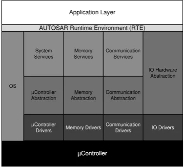
To make software components independent from the hardware which consists of multiple Electronic Control Units (ECUs), the interface to this hardware must be standardized. This is done using the AUTOSAR basic software, shown in Figure2.
µController µController
Application Layer
AUTOSAR Runtime Environment (RTE)
Communication Abstraction Memory Abstraction µController Abstraction Communication Services OS Memory Services System Services IO Hardware Abstraction IO Drivers Communication Drivers Memory Drivers µController Drivers
Figure 2: Structure of the AUTOSAR basic soft-ware, the run-time environment and the applica-tion layer.
This middleware consists of a real-time op-erating system based on the OSEK/VDX stan-dard [OSE05]. The operating system sched-ules tasks in a fixed priority way. Since the concept of a task is not known at the func-tional level, the components must first be mapped to the processors and the runnables must subsequently be mapped onto tasks. The mapping to tasks is not necessarily one-to-one. The rules for mapping runnables to tasks are defined in the Run-Time Environ-ment (RTE) specification, available on the AUTOSAR website. All tasks have to be as-signed a priority to be scheduled by the oper-ating system.
The middleware also contains services for sending and receiving messages on a commu-nication bus. These are composed of signals that originate in the application layer.
property and the message transmission mode, that have an impact on the timing behaviour of the application. More information about the configuration parameters in the communication stack can be found in the AUTOSAR communication specifications available on the AUTOSAR website.
On the communication abstraction and driver layer, the most common automotive buses, such as the Controller Area Network (CAN), are currently supported by the AUTOSAR communi-cation stack. These also have a plethora of configuration parameters that impact the real-time behaviour of the full system, such as the priority of the frames containing the message.
The RTE is used as glue between the functional components and the AUTOSAR basic soft-ware. It is responsible for storing the internal messages using buffers or forwarding the external messages to the communication stack. It also activates the runnables when an event occurs.
It becomes evident that taking into account all the variability illustrated so far results in a com-binatorial number of possible deployments, which has to be typically managed by some domain expert. Such a task would greatly benefit from automation support, especially in determining available deployment alternatives at a given development stage.
3
Related work
Performance analysis is crucial for the deployment of safe and cost-effective software-intensive systems. Balsamo et.al. [BDIS04] present a review of research in the field of model-based per-formance prediction. The techniques are based on simulation models, process algebra, Petri nets and stochastic processes. An example of methods close to our research is architecture-based performance analysis [SG98] where a performance model, based on queuing networks, is de-rived from a system described in UML. For the design and deployment of software components, Palladio [BKR09] offers a meta-model with annotations to describe extra-functional properties. The model can be transformed into both an analytical and a simulation model. Kugele et al. [KHTW09] use a similar approach by annotating a component-based meta-model with extra-functional properties. Part of the deployment is automated using an integer linear programming approach.
Platform-based design [KNRS00, SM01] introduces clear abstraction levels and allows for separation of concerns between the refinement of the functional architecture specification and the abstractions of possible implementations. Di Natale and Sangiovanni-Vincentelli [SD07] adapted the platform-based technique to the development of automotive embedded systems. The definitions of the models and architecture solutions, involved in the AUTOSAR process, are isolated from the details while still allowing enough information for the accurate prediction of the implementation’s properties. The process is driven by a what-if analysis.
Popovici et al. developed an exploration technique based on platform-based design for the deployment of multimedia applications on MPSoC architectures [PGR+08]. The technique al-lows software code generation, software development platform generation and simulation model generation. This allows easy experimentation with different mappings of the software on the architecture. Different levels of abstraction are defined at which the generation, simulation and validation of the software components can take place.
DECOS architecture enables the transition from a federated to a more integrated distributed ar-chitecture, integrating multiple subsystems on a single platform. As a consequence, the platform choices are less open and depend on a time-triggered communication bus. The developer is as-sisted during the deployment by a commercial tool, TTTech toolsuite, for schedulability analysis. In addition to the above performance analysis methods and deployment space exploration tech-niques there are some other automatic methods for local optimization. These methods optimize a certain part of the deployment space. Some use heuristic search methods, such as simulated annealing [PEP02], genetic algorithms [Sin07], or use linear programming [ZZDS07] or SAT-solving [MH06].
Sch¨atz et al. developed a rule-based transformation technique [SHL10] based on Prolog to generate the full deployment space of an embedded system.
Finally, The DESERT tool-suite [NSKB03] provides a framework for design space explo-ration. It allows an automated search for designs that meet structural requirements. Possible solutions are represented in a binary encoding that can generate all possibilities. A pruning tool is used to allow the user to select the designs that meet the requirements. These can then be reconstructed by decoding the selected design.
Our technique incorporates platform-based design by introducing clear abstraction layers for deployment space exploration. At every abstraction level validation methods exist where the configuration can be checked. The exploration is done automatically by generating the full de-ployment space, at that level of abstraction, using transformations.
4
Incremental refinement of deployment decisions
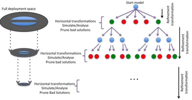
Full$deployment$space$ Horizontal$transforma5ons$ Simulate/Analyse$ Prune$bad$solu5ons$
…
Horizontal$transforma5ons$ Simulate/Analyse$ Prune$bad$solu5ons$ Horizontal$transforma5ons$ Simulate/Analyse$ Prune$Bad$Solu5ons$ Re fin em en t$ $tr an sf or m a5 on $ Re fin em en t$ $tr an sf or m a5 on $ Start$model$ Re fin em en t$ $tr an sf or m a5 on $Figure 3: Automatic Deployment Space Exploration Approach.
formal-ism(s) [VDM02]. For this purpose two types of transformations are used:
• Refinement Transformations: Deployment can be viewed as a set of transformations since we iteratively add knowledge about the platform to the model. By using these transfor-mations we can generate all possible solutions allowed within the syntactic constraints imposed by the meta-model. Every transformation may yield multiple solutions, which causes an explosion of the search space. Therefore, it is important that non-conforming solutions are pruned as early as possible. To achieve this, multiple layers of abstraction are defined where high-level estimators can be found to check the generated partial solutions. • Horizontal Transformations: The model is transformed to another formalism at the same abstraction level making it amenable to evaluation of its suitability using simulation or analytical techniques.
The solution space is reduced with every abstraction layer since the pruned branches are not further explored. The choice of analysis method needs to match the system properties that are optimized. Here, we are interested in the performance of the system. For the deployment ex-ploration in the context of real-time behaviour we identified three abstraction levels. The levels are pragmatically chosen so they correspond to the analytical and simulation methods currently available in the automotive industry. For each of these levels we describe what information has to be available and what method is used to obtain the high-level estimator.
The first defined level abstracts thesystem architecture. Here, the software components of the application are mapped to a specific hardware component. In case of multiple components, a bus connects these components. Since all information about timing of the triggers and execution time is known at this point, we can use a simple bin packing check to ensure that no single component or bus is overused at this level of abstraction.
The next abstraction level concentrates on theservicesprovided by the communication stack and operating system. The runnables are grouped into tasks and they are given a priority. The same is done for the signals that are to be transmitted on the bus. These are grouped into messages and given a priority for the arbitration on the bus. Furthermore, signals and messages are given their transmission mode and property. At this abstraction level all information for schedulability analysis is present. This means that solutions that cannot meet their end-to-end deadlines are automatically pruned.
Finally, the application is fully mapped to the hardware platform by defininghardware buffers
for the reception and transmission of messages. The drivers and interfaces of the communica-tion stack are configured and software buffers are defined. Some hardware-specific opcommunica-tions are also configured. The solutions are checked for their real-time behaviour under the influence of buffering. We use a DEVS simulation model presented in [DVR+11] for this purpose. Solutions that have lost messages and/or that cannot make their end-to-end deadlines under the influence of buffering are pruned in this step.
It is important to note that the evaluation cost increases with every refinement step. The bin packing check is cheap in terms of computation while running a simulation is very expensive.
4.1 Refinement transformations
Programming (ASP) [GL88]. The transformation engine is based on a generation mechanism that first expands the set of possible solutions based on mapping rules and then refines such a set by applying constraints on the derived target models, such as meta-model conformance rules and additional desired characteristics1. In our case, solution space exploration can be reduced to an endogenous model transformation (the AUTOSAR meta-model spans all the abstraction levels), where the source and target models both conform to the same meta-model. Then, starting from a certain source model containing an incomplete deployment at a given development stage, it is possible to derive target models representing available deployment alternatives for the next abstraction level. For instance, it is possible to specify that if a boolean flag is present in the source model, then two different target models will be generated, one for the flag set to true and one for flag set to false. Similarly, it is possible to generate multiple assignment possibilities of hardware buffers to handlers.
4.2 Horizontal transformations and pruning
It is our goal to pick the deployment configuration that promises desirable extra-functional be-haviour. For each possible configuration that was calculated in the previous step, we predict and analyse the behaviour of the system.
5
Case study
To show that the proposed technique is feasible, we apply it to part of the deployment of an automotive power window. In our case study, the first two abstraction levels in the process have been used to prune the search space and we start with models abstracted at the service level.
5.1 The power window
The software model of our power window case study is based on [PM04]. The application controls the window on the passenger side, though both passenger and driver are allowed to open or close the window. When an object is present while closing the window, this will be detected and the window will be lowered.
Figure 1 shows the application model of the power window application.
Runnables and states in runnables
Control Driver 8.96µs Control Passenger 5.01µs Sensor Load 81.2µs
Logic 39.7µs
DC Motor 2.0µs
Table 1: Execution times of the power window components.
The functional model of an AUTOSAR based power window consists of 5 atomic software components. All components contain a sin-gle runnable except for the Driver component containing 3 runnables, each for reading a sin-gle sensor. The runnables are triggered us-ing a timus-ing event every millisecond. Table
1shows the execution timings of the different components on a 32-bit platform.
For the case study we implemented an
AU-TOSAR like meta-model with annotations for execution timing using the EMF Ecore framework
1JTL has a number of interesting features that go far beyond the scope of this paper. The interested reader can start
[SBPM08]. We generate all possible solutions starting from a single model that has been checked by schedulability analysis. The model’s variation points contain:
• Transmit and Receive buffers: The number of hardware buffers in the CAN controller are bounded. Therefore they must be distributed between transmission and reception buffers. Once they are partitioned, the frames need to be assigned to a hardware buffer. Hardware buffers can be overwritten if a message has not been transmitted yet. This makes this a crucial parameter in the real-time behaviour of the whole system.
• CAN interface module software buffering: This flag enables or disables the use of software buffers in the CAN interface basic software module. If software buffering is allowed, the message can be stored in software when the hardware buffer is full.
• CAN Transmit Cancellation: The transmit cancellation flag enables the cancellation of a message inside the CAN hardware buffer when a higher priority message is available. This could impact the real-time behaviour of the system as messages may be transmitted in a different order than they are received in.
• CAN Multiplexing: The CAN hardware normally checks the buffers in a linear fashion, transmitting the first buffer that is not empty. By allowing multiplexing, the buffers of CAN become a priority queue. It will always transmit the highest priority message first.
5.2 Implementation of the refinement operations
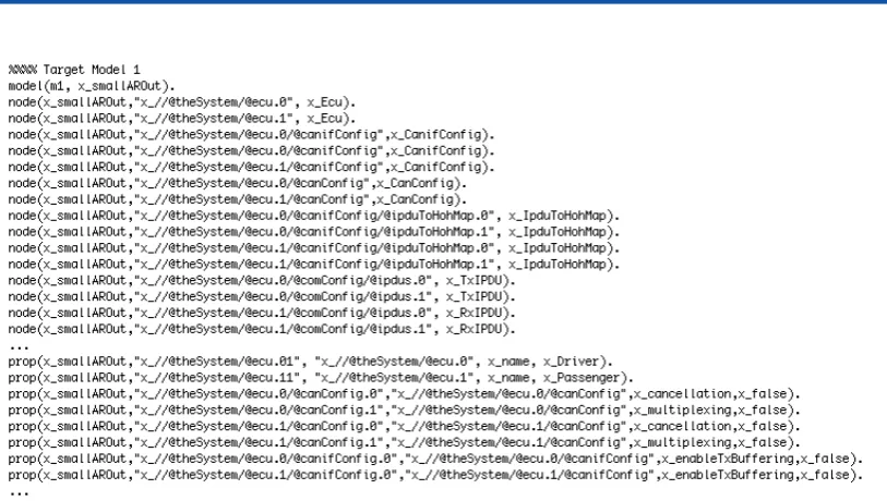
Based on the variabilities described above, a first transformation has been written that explores the solution space without any additional constraints. Given the number of variables and the corresponding possible evaluations, the execution yielded 192 solutions. However, as previously discussed, it is possible to add some domain knowledge in the form of new constraints to the JTL transformation to narrow down the solution space. For instance, ECUs not transmitting any frames make the CAN cancellation, multiplexing, and software buffering flags obsolete. Therefore, the transformation specification has been enriched with such domain knowledge. As the source model contains an ECU transmitting no frames (i.e., the Passenger), the solution space has been reduced to 24 possible solutions. In Figure 4, an excerpt of the deployment alternatives generated by the JTL transformation is shown2. In particular, it is possible to see a generated configuration as conforming to the abstract syntax exploited by JTL.
5.3 Implementation of the horizontal transformations
The solutions generated from the refinement transformation are transformed into a DEVS simu-lation model, as described in [DVR+11]. This model is a parametrized simulation model written in Python. All control units, tasks, messages, buffers and their properties need to be specified and are executed by the pyDEVS simulation engine.
We use the MOF Model to Text Language (MTL) [OMG08] defined by the OMG to transform the configuration model into Python source code for the DEVS simulation. MTL is a template-based transformation language, allowing us to output Python code and inject the configuration
2The details of the JTL transformation for alternatives exploration can not be put in this paper due to space
Figure 4: An excerpt of deployment alternatives generated by the JTL transformation.
parameters from the model. The result of this transformation is customized Python code for the DEVS simulation of the chosen configuration.
5.4 Results
The simulation calculates a metric based on the end-to-end latencies of the application, the re-sponse times of the tasks and the idle-time of the processors. If messages were lost, the score was reduced to zero. Figure5shows the results of the 24 variants. Our method found 8 optimal
12# 12.5# 13# 13.5# 14# 14.5# 15#
1# 2# 3# 4# 5# 6# 7# 8# 9# 10# 11# 12# 13# 14# 15# 16# 17# 18# 19# 20# 21# 22# 23# 24# Real%&me(behaviour(of(the(PWC(variants(
Series1#
Figure 5: Real-time behaviour of the powerwindow case study (higher score is better). On the X-axis: the 24 solutions, on the Y-axis: the score.
solutions while four solutions did not make the deadline since there were messages lost during execution.
6
Lessons learned and open issues
One general issue of exploration techniques is the explosion of the search space. We can ap-proach these problems by parallel computation, as the branches are independent. Each alterna-tive can be simulated and refined independently of the other alternaalterna-tives. Still, any opportunity to prune the search space should be exploited as this space grows exponentially with the number of different deployment choices. Today, the AUTOSAR developer needs to explore the whole solution space manually, or apply best practices. Manual exploration is only possible for ex-tremely small configuration spaces and best practices might miss the optimal combinations of deployment choices. Our approach, grouping the deployment choices in different abstraction layers, allows domain experts to focus on concepts closer to their expertise.
Our current approach targets the optimization of one system property, performance. The method allows for multi-objective optimization, allowing us to optimize for safety, performance and cost. It will be necessary to combine several parameter evaluations at the same level of ab-straction, entailing trade-off computations. The developers must then choose between all Pareto optimal solutions.
A variety of optimizations can be added to our approach. If at a given point the solution fails, that branch is not explored further. There could be conditions for which further pruning of the solution space can be applied, tracking the set of choices back in the search tree. Other optimizations could be added by domain experts, as we did. They can define extra constraints to the exploration of the branches resulting in fewer solutions.
7
Conclusions and future directions
This paper proposed anautomatic deployment exploration techniquebased onrefinement trans-formations and platform-based design. We have shown that the techniques involved in the method are feasible with currently available tools. To illustrate the automatic exploration, we applied it to part of an automotive power window. The solution is optimized for its real-time behaviour using an AUTOSAR-like meta-model. First results are promising and show that the optimal solution can be found with our approach.
We will continue this work in multiple directions: (a) We will extend the transformations to include the three defined levels so a complete optimization of the power window can be done; (b) Other trade-offs can be included in the process, for example memory and safety requirements; (c) The power window is too small to verify whether the method is feasible for a real subsystem in the automotive domain. Therefore, larger case studies will be done to investigate this; (d) By doing empirical research with this method, more domain knowledge could be discovered and included in the method so more non-optimal solutions can be pruned earlier on (cfr. sensitivity analysis).
Bibliography
[AUT08] AUTOSAR. AUTOSAR methodology, 1.2.1. 2008. online:www.autosar.org.
[BDIS04] S. Balsamo, A. Di Marco, P. Inverardi, M. Simeoni. Model-based performance pre-diction in software development: a survey.IEEE Transactions on Software Engineer-ing30(5):295–310, May 2004.
[BKR09] S. Becker, H. Koziolek, R. Reussner. The Palladio component model for model-driven performance prediction. Journal of Systems and Software 82(1):3–22, Jan. 2009.
[CDEP11] A. Cicchetti, D. Di Ruscio, R. Eramo, A. Pierantonio. JTL: A Bidirectional and Change Propagating Transformation Language. In Malloy et al. (eds.),Software Lan-guage Engineering - 3rd Int. Conf., SLE 2010, Eindhoven, The Netherlands, Octo-ber 12-13, 2010, Revised Selected Papers. Lecture Notes in Computer Science 6563, pp. 183–202. Springer, 2011.
[CFJ+08] P. Cuenot, P. Frey, R. Johansson, H. L¨onn, M. Reiser, D. Servat, R. Koligari, D. Chen. Developing automotive products using the EAST-ADL2, and Autosar compliant architecture description language. In Embedded Real-Time Software Conference, Toulouse, France. Pp. 1–10. 2008.
[DVR+11] J. Denil, H. Vangheluwe, P. Ramaekers, P. De Meulenaere, S. Demeyer. DEVS for AUTOSAR Platform Modelling. InSpring Simulation Multiconference. Pp. 67 – 74. Society for Computer Simulation International (SCS), April 2011. Boston, USA.
[GL88] M. Gelfond, V. Lifschitz. The Stable Model Semantics for Logic Programming. In Kowalski and Bowen (eds.),Proceedings of the Fifth Int. Conf. on Logic Program-ming. Pp. 1070–1080. The MIT Press, Cambridge, Massachusetts, 1988.
[HSS+07] W. Herzner, R. Schlick, M. Schlager, B. Leiner, B. Huber, A. Balogh, G. Csertan, A. Le Guennec, T. Le Sergent, N. Suri, S. Islam. Model-Based Development of Dis-tributed Embedded Real-Time Systems with the DECOS Tool-Chain. In Procs. of 2007 SAE AeroTech Congress & Exhibition. Citeseer, 2007.
[KHTW09] S. Kugele, W. Haberl, M. Tautschnig, M. Wechs. Optimizing Automatic De-ployment Using Non-functional Requirement Annotations. In Margaria and Stef-fen (eds.),Leveraging Applications of Formal Methods, Verification and Validation. Communications in Computer and Information Science 17, pp. 400–414. Springer, 2009.
[MH06] A. Metzner, C. Herde. RTSAT An Optimal and Efficient Approach to the Task Allo-cation Problem in Distributed Architectures. InReal-Time Systems Symposium, 2006. RTSS’06. 27th IEEE International. Pp. 147–158. IEEE, 2006.
[NSKB03] S. Neema, J. Sztipanovits, G. Karsai, K. Butts. Constraint-based design-space explo-ration and model synthesis. InEmbedded Software. Pp. 290–305. Springer, 2003.
[OMG08] OMG. MOF Model to Text Language (MTL). Technical report, OMG, Jan. 2008.
[OPH06] R. Obermaisser, P. Peti, B. Huber. DECOS: an integrated time-triggered architecture.
Elektrotechnik und Informationstechnik123(3):83–95, 2006.
[OSE05] OSEK. OSEK/VDX Specifications of the OS 2.2.3. 2005.
[PEP02] T. Pop, P. Eles, Z. Peng. Holistic scheduling and analysis of mixed time/event-triggered distributed embedded systems. In Proceedings of the tenth international symposium on Hardware/software codesign. Pp. 187–192. 2002.
[PGR+08] K. Popovici, X. Guerin, F. Rousseau, P. S. Paolucci, A. A. Jerraya. Platform-based software design flow for heterogeneous MPSoC.ACM Transactions on Embedded Computing Systems7(4):1–23, July 2008.
[PM04] S. Prabhu, P. Mosterman. Based Design of a Power Window System: Model-ing, Simulation and Validation.Proceedings of IMAC-XXII: A Conference on, 2004.
[SBPM08] D. Steinberg, F. Budinsky, M. Paternostro, E. Merks. EMF: Eclipse Modeling Framework (2nd Edition). Addison-Wesley Professional, 2 edition, Jan. 2008.
[SD07] A. Sangiovanni-Vincentelli, M. Di Natale. Embedded System Design for Automotive Applications.Computer40(10):42–51, Oct. 2007.
[SG98] B. Spitznagel, D. Garlan. Architecture-based performance analysis. In Proceed-ings of the 1998 Conference on Software Engineering and Knowledge Engineering. Pp. 19–20. Citeseer, 1998.
[SHL10] B. Sch¨atz, F. H¨olzl, T. Lundkvist. Design-Space Exploration through Constraint-Based Model-Transformation. In 17th IEEE International Conference and Work-shops on Engineering of Computer-Based Systems. Pp. 173–182. IEEE, 2010.
[Sin07] O. Sinnen.Task scheduling for parallel systems. Wiley-Interscience, 2007.
[SM01] A. Sangiovanni-Vincentelli, G. Martin. Platform-based design and software design methodology for embedded systems.IEEE Design & Test of Computers18(6):23–33, 2001.