TECHNICAL UNIVERSITY OF CLUJ-NAPOCA
ACTA TECHNICA NAPOCENSIS
Series: Applied Mathematics, Mechanics, and Engineering Vol. 60, Issue II, June, 2017
RESEARCH OF NICKEL-ALUMINUM BRAZING
Nicu-Marian TRANDAFIR, George ARGHIR
Abstract: The filler metal Nocolok Sil Flux with 33,3 % silicon is an ideal material for braze some nickel plates with an aluminum plate, in a heat exchanger intended to hybrid vehicles. The Ni/Al brazed joint made with Nocolok Sil Flux has a higher quality compared the Ni/Al brazed joint made with Nocolok Flux. This quality refers especially to: less defects at the Ni/Al interface due the fluidity which silicon confers to the filler metal and due the complete filling of capillary spaces between base metals; uniform thickness; greater mechanical resistance; sustainability and traceability; improve the energy exchange which the heat exchanger must ensure due the better acoustic properties of silicon. Nocolok Sil Flux it is certainly a very good alternative.
Key words: brazing, nickel-aluminum brazing
1. INTRODUCTION
The oil fuel is exhausted in an exponential manner, as it is known. Moreover, this fuel is highly polluting and harmful to the Earth's atmosphere and biosphere, fauna and the entire humankind. In this sense, to reduce the excessive consumption of oil and petroleum products and to eliminate the disastrous effects of their combustion, electric cars are to be used, respectively hybrid vehicles. Such vehicles have in their component a particular type of heat exchanger with cooling fins (cooler), which cool the fluids from the engine.
This article proposes to research the connection of some parts of the cooler, namely the joints between the nickel plates and an aluminum plate. That connection is obtained by brazing, in a horizontal furnace, operating continuously under a nitrogen atmosphere. The inspection of nickel-aluminum brazing is done by a non-destructive method, the best being scanning acoustic microscopy. The inspection is performed using a SAM 301 scanner, which uses the ultrasound waves to create 2D and 3D images. It is possible a detailed inspection, by this method, of the brazed joint at the micrometer level, detection and observation of the defects being carried out
with a high accuracy [1].
2. FACTORS WHICH INFLUENCE THE BRAZING OF Ni/Al. MATERIALS
Brazing is a hot joining process, using a filler (metal) material, different from the starting materials (base metals) [2]. The brazing is performed at a temperature higher than 450 0C,
respectively, around 600 0C, maximum 25
minutes. The factors influencing the brazing of Ni/Al are:
-the physical parameters of the brazing furnace (brazing temperature, brazing time, conveyor speed, flow rate of nitrogen, oxygen level, dew point, etc.);
-mounting devices (device type, the pressure of devices which squeeze the pistons). The gap between base metals must be 0.05-0.08 mm [3]. The base metals used to this brazing are selected according to Unified Numbering System (UNS) of the International Standard and are the following:
- nickel: W2.4068 HV100 (almost pure);
(aluminum), being actually the alloy AlSi10.The filler metals used are:
- Nocolok Flux(KAlF4) (suspension);
- Nocolok Sil Flux (paste).
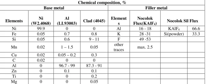
The chemical compositions of base metals and filler metals are shown in Table 1 [4, 5]:
Table 1. Chemical composition of base and filler metals
3. THE INFLUENCE OF THE FILLER METALS ON THE Ni/Al JOINT
It is considered that due to the overlap of two metals, at not more than 40 nm, the two metals form a permanent inter-metallic connection due to basically attractions between the metal atoms. Capillary action promotes a very good brazing when contacted surfaces are wetted by the filler metal, the result of the capillary being the attraction of the fluid atoms to the atoms of the solid, in a small area.
The filler metals must meet the following minimum conditions to ensure brazing of two metals:
-to possess optimal fluidity at the brazing temperature, such that to ensure capillary filling and a uniform distribution in the joint;
-high stability, in order to avoid premature release of some elements, which melt at low temperatures;
-low volatility of its elements at brazing temperature;
-able to wet surfaces of base metals that come into contact with and the ability of the dispersion;
-to avoid possible erosion that may arise between them and base metals within the required limits to make this brazing;
-to be capable of diffusion in the basic metals,
especially if the latter melts at high temperature (nickel);
-the possibility to dissolve the aluminum oxide film on the surface of the base metal and to protect that surface from a new oxidation [6]. The two mentioned Nocolok fillers fulfill all these conditions. However, it will be performed two experiments designed to emphasize the advantages of using one of the two filler metals.
3.1. Utilization of Nocolok Flux filler metal
It was recommended as filler metal, the Nocolok Flux (white) as brazing fluxes. Indeed, this flux is particularly suitable if the base metal is aluminum and is widely used. The fluxing is made in this case, by immersion the components for brazing in a pool, where is a suspension of Nocolok Flux, being equipped with stirrers. The fluxing is followed by drain. Figure 1 shows the contact of base metals (nickel and aluminum) with Nocolok Flux as filler metal:
In this experiment, they were used as base metals: an imprinted nickel plate with thickness of 1 mm and an aluminum plate with a thickness of 2 mm (nickel surface subjected to contact with the aluminum have some punch marks on them in order to high adhesion); base metal surface is 875 mm2 (35x25 mm). A suspension
Chemical composition, %
Base metal Filler metal
Elements Ni
(W2.4068)
Al
(LL93003) Clad (4045)
Element s
Nocolok
Flux(KAlF4) Nocolok Sil Flux
Ni 99.9 0 0 Al 16 - 18 KAlF4 66.6
Fe 0.05 0.7 0.8 K 28 -31 Si(powder) 33.3
Si 0.05 0.6 9 - 11 F 49 -53
Mn 0.02 1 – 1.5 0.05 other
traces max. 2.5
Cu 0.02 0.05 – 0.2 0.3
C 0.02 0 0
Al 0 96.7 - 99 87.3 - 91
Zn 0 0.1 0.1
Ti 0 0 0.2
of Nocolok Flux with a 0.2 mm thickness of the initial layer was used as filler metal.
Fig. 1. The contact between base and filler metal by Nocolok Flux. Digits: 1, 0.2, and 2 are in mm.
The base metals and the filler metals fluxed and mounted are introduced into the furnace. After the transformations that this type of flux supports at the brazing, result hydrofluoric acid (HF) which is released, but even small amounts of potassium and aluminum fluorides; the main component remain the aluminum from the clad
4045 of the base metal (also of aluminum). On leaving the oven, the brazed assembly is cleaned and subjected to an ultrasound control at scanner 301 SAM, in order to detect any defects. The range of transducer on x and y axis is 320 mm: the acoustic waves are generated by a piezoelectric transducer and the signal is sent via a sapphire cylinder to the lens integrated inside of it. This acoustic microscope works with the echo pulse technique. A special
acoustic objective transmits and receives short acoustic pulses of a high repetition rate and after interacting with the object, the reflected acoustic waves are converted into video signals. To compose an image the acoustic objective is
moved over the sample in a meander scan. The intensity and phase of the reflected signals are displayed sequentially in synchronization with the raster dots as a grey value on the high
resolution screen.
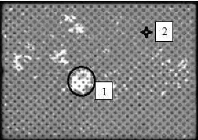
Longitudinal ultrasonic scanning was carried out at exactly nickel-aluminum interface as is illustrated in Figure 2, (C-scan):
Fig. 2. The ultrasound scan at interface Ni/Al (C-scan): 1-bump and 2-brazed joint flawless.
In the scan, Figure 2, grey indicates a brazed joint Ni/Al, but unfortunately there are defects of white color (pores small and large). The defects are dispersed both the middle and in the vicinity edges; they are in number of at least 5. The total percentage of defects is 3.52%; so, 96.48% from the joint is well brazed. Scanner parameters used are located in Table 2 and Table 3.
Tabel 2. Scanner parameters
Tabel 3. Scanner parameters
The areas of the five major defects resulting from ultrasound scan, ranging between 0.85 and 11.62 mm2. Their depths can be detected in the
called B-scan cross section, Figure 3. The biggest defect will be sectioned in the longitudinal scan (C-scan) and transposed into
Fig. 3. Cross section of the biggest defect (B-scan).
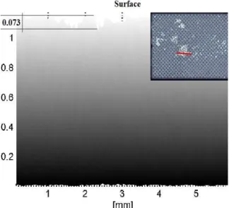
In Figure 4 is viewable the height of the defects in the Ni/Al brazed joint and the highest defect has 0.224 mm to an ideal right plan. Actually, a
bump is inside the joint (Figure 2, point 1).
Both brazed joint and defects have certain amplitude based on time. That amplitude provides information about the size of the defects and how these defects have damaged the brazed joint. To view the amplitude variation over time is required an acoustic histogram of that joint, called A-scan. Subsequently, if the speed of ultrasound in the brazed joint is known, one can calculate the wavelength, acoustic impedance,the coefficient of reflection- transmission, etc. To do this, it must be
considered in Figure 2, two distinct points on the longitudinal scan.
Fig. 4. Height of the defects in 3D at Ni/Al interface.
The first point selected in Figure 2 (surrounded in black) on the white area (1) is the biggest flaw and the second point selected (2), like a little star is the brazed joint flawless. The difference between their signals and their amplitudes is shown in the histogram from Figure 5. In this histogram is displayed on the abscissa the Time-Of-Flight (TOF) and in the ordinate amplitudes of signals; TOF represent a technique for calculating the distance to a target by using the timing of the return echo from target utilizing the speed of sound in the medium between two references points; measured in nanoseconds.
Fig. 5. Histogram of the signals(A-scan). The difference amplitude at the top (∆A)
between brazed joint and defect to a steady state zero is:
∆A(Al)= Adefect - Abrazed,
∆A(Al) = 0.992 V - 0.547 V,
∆A(Al) = 0.445 V,
where: ∆A(Al) – amplitude difference, V;
Adefect – amplitude of defect, V;
Abrazed – amplitude of brazed joint, V;
(approximate 7 dB);
In this case, the amplitude is measured as a voltage signal, because for the acoustic signal is received by pre-amplifier as electrical signal. Similarly, there is a time difference (delay -
∆TOF) as follows:
∆TOF(Al) - tbrazed - tdefect,
∆TOF(Al) = 22850 ns – 22840 ns,
∆TOF(Al) = 10 ns,
where: ∆TOF(Al) - time difference;
tdefect - travel time of longitudinal wave through
defects, ns;
tbrazed = travel time of longitudinal wave through
brazed joint, ns;
The speed of ultrasound in this brazed joint is that of mainly metal in the joint (Al) and namely:
c(Al) = 6374 m/s.
Knowing the speed of ultrasound and the frequency (f = 4.2 kHz) in this combination, it can quickly calculate the longitudinal wavelength which has the formula:
λ(Al) = c(Al)/f; so,
λ(Al) = 6374 m/s/4200 Hz,
λ(Al) = 1.51 mm,
λ(Al) - wavelength, mm;
c(Al)- speed of ultrasound in the brazed joint,
m/s;
f - frequency of the ultrasounds in the brazed joint, kHz.
One of the characteristics of the brazed joint is the acoustic impedance (Z). It is in fact, the
opposition to displacement of its particles by sound and is given by:
Z(Al) = p(Al) x c(Al),
Z(Al) = 2,7kg/cm3 x 6340 m/s,
Z(Al) = 17209.8 kg m-2 s-1.
This measurement unit is equivalent acoustic ohms, respectively, Rayl and is given by:
Z(Al) = 17.209 MRayl, where:
Z(Al) - specific acoustic impedance of the brazed
joint, MRayl;
p(Al) – density of Al, kg/m3;
c(Al) - the speed of ultrasound in the brazed joint,
m/s;
The boundary between two materials of different acoustic impedances is called an acoustic interface. When sound strikes an acoustic interface at normal incident, some amount of sound energy is reflected and some amount is transmitted across the boundary. So if known, the specific acoustic impedance of the brazed joint and acoustic impedance of the first base metal (nickel), it can determine the acoustic reflection coefficient with the formula:
R = Z2 – Z1 / Z1 + Z2, where:
R(Al) = Z(Ni) - Z(Al) / Z(Ni) + Z(Al);
R(Al) - the reflection coefficient of the brazed
joint;
Z(Al) - specific acoustic impedance of the brazed
joint;
Z(Al) = 17.209 Mrayl
Z(Ni) - acoustic impedance of nickel,
Z(Ni) = 51.79 Mrayl
So, R(Al) = 51.79 – 17.209 / 51.79 + 17.209,
R(Al) = 34.581 / 68.999,
R(Al) = 0.5.
That means: 50 % of the energy is reflected and 50 % is transmitted.
3.2. Utilization of Nocolok Sil Flux filler metal
pistol. The composition consists of Nocolok Flux (KAlF4) and 33.3% pure silicon powder.
After brazing, in furnace is released HF and fluorides are formed, as in the first filler metal; consequently, silicon remains the majority in
the brazed joint. Because silicon has a high melting point (14140C) compared to aluminum,
it is less active in this and not form an alloy itself, but rather the inter-metallic phase at temperature of brazing aluminum (600 0C). The
assembly of the base metal with this type of filler metal is shown in Figure 6:
Fig. 6. The contact between base metals and Nocolok Sil Flux filler metal. Digits: 1, 0.2, and 2 are in mm.
All dimensions of base metals and filler metal are similar to the first case; as well, the scanner parameters of the acoustic microscope.
Longitudinal ultrasonic scanning was carried out exactly at the nickel-silicon-aluminum, interfaces and is illustrated in Figure 7 (C-scan).
Fig. 7. The ultrasounds scan at interface Ni/Al (C-scan): 1-cavity and 2- brazed joint flawless.
As it is obvious, pasted portion is much higher; the defects are less (only two). Total percentage of the defects is 0.39%; so 99.61% from the joint is well brazed.
The areas of the two defects resulting from scanning ultrasonic range are between 1.55and 2.48 mm2. The depth of these two defects was
studied in cross section (B-scan), as shown in Figure 8. The biggest flaw depth is 0.041 mm from the surface of Ni/Al interface. The entire brazed joint has of 1.15 mm thickness. To calculate the acoustic parameters (amplitude, TOF, wavelength, acoustic impedance, coefficient of reflection-transmission), must reconsider in Figure 7, two distinct points in the longitudinal scan (C-scan) as follows: one (1) is the biggest flaw and second (2) is brazed flawless joint, symbolized with a little star.
Fig. 8. Cross section of the biggest defect (B-scan).
In Figure 9, right side, it can observe a little
cavity like a black spot, which is in fact, the
biggest defect at Ni/Al interface. This cavity has a depth equal with that found in B-scan, namely: 0.041 mm. This defect is smaller than first and has smaller depth as well.
The difference between the signals, amplitudes and times is shown in Figure 10. This figure is simplified because the incident signals are
identical, the interface Ni/Al being the major concern.
Fig. 10. Histogram of the signals(A-scan).
The difference amplitude at the top (∆A)
between brazed joint and defect to a steady state zero is:
∆A(Si) = Adefect - Abrazed,
∆A(Si) = 0.813 V - 0.508 V,
∆A(Si) = 0.305 V;
Time difference (delay - ∆TOF) is:
∆TOF(Si) = tdefect - tbrazed,
∆TOF(Si) = 22942 ns – 22941 ns,
∆TOF(Si) = 1 ns
The speed of ultrasound in this brazed joint is that of mainly metal in the joint (Si) and namely:
c(Si) = 8430 m/s.
Knowing the speed of ultrasound and the frequency (f = 4.2 kHz) in this combination, it can calculate the longitudinal wavelength which has the formula:
λ(Si) = c(Si)/f;
so, λ(Si) = 8430 m/s/4200 Hz,
λ(Si) = 2 mm.
The acoustic impedance (Z) is:
Z(Si) = p(Si) x c(Si),
Z(Si) = 2,33 kg/cm3 x 8430 m/s,
p(Si) -density of silicon;
Z(Si) = 19641.9 kg m-2 s-1;
So, Z(Si) = 19.641 MRayl.
The reflection coefficient of the brazed joint is:
R = Z2 – Z1 / Z1 + Z2 and means:
R(Si) = Z(Ni) - Z(Si) / Z(Ni) + Z(Si),
Z(Ni) = 51.79 Mrayl
R(Si) = 51.79 – 19.64 / 51.79 + 19.64,
R(Si) = 0.45
That means: 45% of the energy is reflected and 55% is transmitted.
4. CONCLUSIONS
increases when trying to braze a metal with a high melting point, like nickel (1455 0C) and
other metal with a lower melting point, like aluminum (660.3 0C). The experiments did in
this article, come to meet this challenge, comparing the properties and qualities of one
filler metal (Nocolok Flux), with those of another filler metal (Nocolok Sil Flux).
So, in conclusion, to braze nickel to aluminum the filler metal Nocolok Sil Flux is much better than Nocolok Flux (KAlF4). It demonstrates the
table below (Table 4):
Table 4. Summary table of values experimental obtained
FILLER METALS
Nocolok Flux Nocolok Sil Flux
Analysis Symbol Value Symbol Value
Number of defects - 5 - 2
Type of defect bump cavity
Percent of defects, % - 3.52 - 0.39
Percent brazed joint, % - 96.48 - 99.61
Biggest area of defect,
mm2 - 11.62 2.48
Defect depth, mm - 0.073 - 0.041
Thickness brazed joint,
mm - 0.7 - 1.15
Silicon content, % - 10 (clad 4045) - 33.3
Density, kg/m3 p
(Al) 2.7 p(Si) 2.33
Density Ni, kg/m3 p
(Ni) = 8.9
Frequency, f, kHz f 4.2 f 4.2
Amplitude difference,
∆A, V ∆A(Al) 0.445 ∆A(Si) 0.305
Delay(∆TOF), ns ∆TOF(Al) 10 ∆TOF(Si) 1
Wavelength, mm λ(Al) 1.51 λ(Si) 2
Longitudinal
sound velocity, m/s c(Al) 6374 c(Si) 8430
Longitudinal sound
velocity Ni, m/s c(Ni) = 4970
Acoustic impedance,
MRayl Z(Al) 17.209 Z(Si) 19.641
Acoustic impedance
Ni, MRayl Z(Ni) = 51.79
Reflection coefficient R(Al) 0.5 R(Si) 0.45
Considering these values experimentally obtained and the benefits it can bring the filler metal contribution compared with other filler metal contribution may be taken into account following statements:
-firstly, the Nocolok Sil Flux is delivered ready for use in the form of homogeneous paste; it applies with a spray pistol, being able to dose properly and accurately, while the Nocolok Flux is a suspension that requires continuous stirring in a pool and the fluxed product should be drained few minutes in inclined plane. Fluxing with Nocolok Sil Flux is a quick and clean operation, downside risk concentration being minimal; Nocolok Flux is a suspension, which requires a constant correction of the concentration within the required limits of said brazing;
-the number of major faults and their sizes are smaller when using Nocolok Sil Flux (2 faults: the largest with an area of 2.48 mm2) compared
to using Nocolok Flux (at least 5 faults: the largest with an area of 11.62 mm2); also, the
percentage of brazed bonded is higher if using Nocolok Sil Flux (99.61%), while when using Nocolok Flux percentage is lower (96.48%). That is due the absence of silicon from the chemical composition of the Nocolok Flux, it being in small quantity only in the composition of the clad 4045 (max. 10 % Si). The silicon content in the Nocolok Sil Flux, is to increase the fluidity of this material at the brazing temperature (reducing the viscosity), being favorably to the process of filling the capillary spaces and adhering well to both the aluminum and nickel. A small number of defects as it ensure the material used Nocolok Sil Flux, gives a high mechanical strength of the connection during operation of the hybrid motor (compressive strength, tensile strength, mechanical shock, etc.). In this way, there will be no thinly to succumb to fatigue.
- the risk of oxidation of the base metal of the aluminum is higher in the case of using Nocolok Flux, due to contact with water, in the preparation of suspension; preparation of the Nocolok Sil Flux paste is no water used;
- Ni/Al brazed joint has a thickness slightly greater and more uniform if using Nocolok Sil Flux (1.15 mm), compared with brazed joint
which the Nocolok Flux was used (0.7 mm); this is due to the dispersion of the filler metal on the entire surface of the nickel brazing subject, without conglomerate. Instead, after drying in the oven, Nocolok Flux loses water, favoring the presence of gaps and thus pores in the brazed joint;
0.5; it means that half of the energy reached at interface Ni/Al is reflected to the transducer and the remaining half is passed on through the interface section aluminum/fin, deeper.
Using Nocolok Sil Flux like filler metal is a very good solution to enlarge the wavelength and thus, penetration depth; that is due mainly silicon in the brazed joint which has a velocity of propagation of ultrasound greater than aluminum, namely: 8430 m/s; this thing leads to increased wavelength from 1.51 mm (case of Nocolok Flux) to 2 mm (the case of Nocolok Sil Flux), at the same lower frequency (4.2 kHz); in the end that favors a deeper penetration and due the lower frequency, even the attenuation is smaller, which means the energy is not absorbed by the brazed joint, but more transmitted. Silicon has the major contribution improving the energy transfer due to the specific acoustic impedance slightly higher than aluminum. That leads to a lower reflection coefficient calculated for Ni/Al interface brazed joint; means: 0.45. So, 45 % of the energy is reflected and the remaining 55 % is sent deeper to the interface aluminum/fin. Thus the filler metal Nocolok Sil Flux contributes not only to improve the non-destructive ultrasonic method,
but also improving a better energy transfer of the cooler.
REFERENCES
[1] PVA TePla Analytical Systems, Winsam 5 User Manual, Westhausen, Germany, 2015, p. 5-15, 20-25.
[2] International/European Engineer, course, ASR(Romanian Welding Society), Technical University of Cluj-Napoca, 2014-2015, p. 1-3. [3] Trandafir N., Arghir G., Brandusan L. Examination of brazing nickel-aluminium, Science and Engineering, 2017.
[4] Nocolok Sil Flux fg, 2017, online www.solvay.com, 04 april 2017, ESST 18:18. [5] Unified Numbering System(UNS), Nickel Alloy UNS O2201, 3000 Series Aluminium Alloy UNS A930003, 4000 Series UNS A 94045, 2017, online www.matweb.com, 08 april 2017, ESST 08:45.
[6] Schwartz Mel M., Sicorsky Aircraft, Toshi Oyama, Mizuhara Howord, Mary B. Vollaro, Miller Jule A.,WESCO INC., Conneticut University, ASM Handbook, Welding, Brazing and Soldering, vol.6, The Materials Information Society, 1993, p.109, 117.
CERCETAREA BRAZĂRII NICHEL-ALUMINIU
Materialul de aport Nocolok Sil Flux cu un conținut de siliciu de 33,3 % este un material ideal pentru brazarea unor plăci
din nichel cu o placă din aluminiu, in cadrul unui schimbător de căldură destinat autovehiculelor hibrid. Îmbinarea brazată
la care s-a utilizat Nocolok Sil Flux este de o calitate superioară îmbinarii brazate la care s-a utilizat Nocolok Flux, acesta
calitate referindu-se concret la: mai putine defectele în interfața Ni/Al datorită fluidității pe care o conferă siliciul
materialului de aport și datorită unei umpleri complete a spațiilor intercapilare dintre materialele de bază; rezistență
mecanică mai mare; grosime uniformă; durabilitate si trasabilitate; îmbunătățește transferul de energie pe care trebuie sa îl
asigure schimbătorul de căldură datorită proprietăților acustice mai bune ale siliciului. Nocolok Sil Flux pentru brazarea Ni-Al este cu siguranță o variantă foarte bună.
Nicu-Marian TRANDAFIR, Engineer, SC RAAL S.A. Bistrita, Ph.D student, Technical University of Cluj-Napoca, [email protected], [email protected]
George ARGHIR, Professor Emeritus, Ph.D, Technical University of Cluj-Napoca, Department of Materials Science and Technology, georgearghir@hotmail,com, Cluj-Napoca, [email protected]