Available online: https://edupediapublications.org/journals/index.php/IJR/ P a g e | 3869
Fuzzy Logic Based Synchronous Reference Frame Control of MLI-
STATCOM in Distribution Network
K.Bhavani & B.Gopal
*PG Scholar, Dept of EEE, KITS Engineering College, Ponnekal; Khammam (Dt); Telangana, India.
**Assistant Professor, Dept of EEE, KITS Engineering College, Ponnekal; Khammam (Dt); Telangana, India.
ABSTRACT:
In this Project Fuzzy based MLI-STATCOM with Synchronous reference frame in Distribution network is presented. In Modern distribution systems have very complex networks connected with linear and nonlinear loads. The presence of harmonics in system it will effected with power quality problems. Due to this high amount of power losses and disoperation of power electronics devices is caused, along with this Harmonics have a number of undesirable effects like Voltage disturbances. These harmonics are needed to mitigate for Power Quality Enhancement in distributed system. To suppress harmonics and other power quality issues related to current, Distribution Static Compensator (DSTATCOM) connected across load is proved to be effective. DSTATCOM is one of the FACTS Devices which can be used to mitigate the harmonics. This paper proposes a five-level diode clamped Multilevel Inverter based Distribution STATCOM (MLI- DSTATCOM) with Synchronous Reference Frame based control for harmonic mitigation. The voltage source converter is core of the DSTATCOM and the hysteresis current control is indirect method of controlling of VSC. In this paper we implement with SRF based DSTATCOM control. SRF theory is implemented for the generation of controlling reference current signals for controller of DSTATCOM. A fuzzy logic control scheme is proposed for the controlling operation of STATCOM. The system performance will analyzed by using MATLAB/SIMULINK software.
Keywords—Multilevel Inverter based Distributed STATCOM (MLI-DSTATCOM); Synchronous Reference Frame (SRF); Power Quality (PQ);
Harmonic Mitigation; Active Power Filter (APF); Total Harmonic Distortion (THD) Fuzzy logic controller.
I. INTRODUCTION
In present day’s power distribution systems is suffering from severe power quality problems [1]. These power quality problems include high reactive
power burden, harmonic(s) currents, load
unbalance, excessive neutral current etc [2]. The measure of power quality depends upon the needs of the equipment that is being supplied. What is good power quality for an electric motor may not be good enough for a personal computer [3]. Usually the term power quality refers to maintaining a sinusoidal waveform of bus voltages at rated voltage and frequency [4]. Some remedies to these power quality
problems are reported in the literature. A group of controllers together called Custom Power Devices
(CPD), which include the DSTATCOM
(distribution static compensator), The
DSTATCOM, is a shunt-connected device [5-7], which takes care of the power quality problems in the currents. Three phase four-wire distribution systems are used to supply single- phase low voltage loads.
Available online: https://edupediapublications.org/journals/index.php/IJR/ P a g e | 3870
as static Var generation, an interface with renewable energy sources, and for battery- based applications [8]. The inverter could be controlled to either regulate the power factor of the current drawn from the source or the bus voltage of the electrical system where the inverter was connected [9]. Several topologies for multilevel inverters have been proposed, the most popular being the diode-clamped, flying capacitor, and cascade H-bridge structures [10- 12]. The pulse width modulation (PWM) cascaded multilevel inverter strategy reduces the total harmonic distortion and enhances the fundamental output voltage [13].
The unique features of fuzzy logic that made it a particularly good choice for many control problems are as follows, it is inherently robust since it does not require precise, noise – free inputs and can be program to fail safely is a feedback sensor quits or is destroyed [14]. The output control is a smooth control function despite a wide range of input variations [15]. Since the fuzzy logic controller processes user- define rules governing the target control system, it can be modify and tweakes easily to improve or drastically alter system performance. New sensors can easily be incorporates into the system simply by generating appropriate governing rules.
In this paper MLI based DSTATCOM with fuzzy logic controller is proposed.
II. OPERATION OF
DSTATCOM
Distribution Static Compensator (DSTATCOM) is connected in parallel like a STATCOM, which is connected at transmission level where as DSTATCOM at distribution level. Its main function is to inject harmonically distorted current in phase opposition to the load current thereby suppressing harmonics in the supply current [7], in addition to this it also supplies required reactive power to the load. A typical block
diagram of a DSTATCOM with unbalanced and
nonlinear load is depicted in Fig.1.
DSTATCOM equivalent circuit is given in Fig.2, where VSabc is phase voltage of supply; VSHabc is a fundamental component of phase output voltage of DSTATCOM and ISHabc is a fundamental component of shunt APF current. The operation of DSTATCOM is explained in the following modes.
Fig.1 Block diagram of DSTATCOM
Fig.2 Equivalent circuit of DSTATCOM Mode 1: If VSHabc is in-phase and equal to VSabc then
DSTATCOM does not inject and absorb any reactive power
Mode 2: If VSHabc is greater than VSabc and I SHabc leads VSabc by some angle, then DSTATCOM will supply there active power of the system. This mode can also be called as capacitive mode and its phasor representation is given in Fig.3 (a). Here DSTATCOM supply all required load reactive power thereby making supply currents free from reactive currents.
Mode 3: If ISHabc lags VSabc then DSTATCOM will take reactive power from the system. This mode can also be called as inductive mode and its phasor representation is shown in Fig.3 (b).
averaged components are stable in nature and are referred to as source current averaged component (𝐼̅
Available online: https://edupediapublications.org/journals/index.php/IJR/ P a g e | 3871
Fig.3 Phasor representation of DSTATCOM From the phasor diagrams it is clear that, DSTATCOM either generates or absorbs the reactive power by
controlling the phase angle (α) between
VSHabc and VSabc thereby
regulating the magnitude of the VSHabc and thus DC Link capacitor voltage.
Fig.4 Shunt Controller using SRF
(1)
III. SYNCHRONOUS
REFERENCE FRAME CONTROL
SRF control is one of the efficient controls to suppress voltage and current harmonics. It referred d-q technique, in which transformations and its inverse transformations of a-b-c to d-q-0 are used . The basic SRF Control technique to generate
reference currents from nonlinear
balanced/unbalanced load is depicted in Fig.4. The load currents of a-b-c coordinates ( ILabc ) are
transformed into d-q-0 coordinates with the help of modified PLL according to the equation (1).These d-q-0 coordinates comprises of an oscillatory
component (𝐼̃oSd and 𝐼̃oSq) and
averaged
component ( 𝐼̅ ASdand 𝐼̅ ASq ) resulting to oscillatory in nature. In order to avoid
oscillatory response and maintain only averaged components of d-q-0 coordinates, a 2nd ordered Butterworth LPF is used. These
For proper compensation, voltage of
DC link capacitor must be kept constant at rated value (i.e. 1200V in this case).The PI controller is therefore used to compensate the loss component of active current (IDloss). Using Ziegler-Nichols’
method, proportional gain (Kp) and Integral gain (Ki) are estimated and are fine tuned to values of 0.003 and 0.0025.The d-axis component of supply current including the active power loss component for capacitor voltage balancing can be represented by
(2)
Available online: https://edupediapublications.org/journals/index.php/IJR/ P a g e | 3872
(3)
These reference currents (IrefSa , I refSb
and I refSc) are compared with load currents (I La
, I Lb and I Lc) to generate DSTATCOM reference
currents iShabc_ref. The currents of the DSTATCOM
are maintained at reference values using Hysteresis current controller as shown in Fig.5. The hysteresis current controller is operated with a lower band 0.25A and higher band of 0.5A to generate switching pulses to a five level diode clamped MLI- DSTATCOM.
Fig.5: Hysteresis current control scheme for five level MLI-DSTATCOM
IV. INTRODUCTION TO FUZZY
LOGIC CONTROLLER
L. A. Zadeh presented the first paper on fuzzy set theory in 1965. Since then, a new language was developed to describe the fuzzy properties of reality, which are very difficult and sometime even impossible to be described using conventional methods. Fuzzy set theory has been widely used in the control area with some application to dc-to-dc converter system. A simple fuzzy logic control is built up by a group of rules based on the human knowledge of system behavior. Matlab/Simulink simulation model is built to study the dynamic
behavior of dc-to-dc converter and performance of proposed controllers. Furthermore, design of fuzzy logic controller can provide desirable both small signal and large signal dynamic performance at same time, which is not possible with linear control technique. Thus, fuzzy logic controller has been potential ability to improve the robustness of dc-to-dc converters. The basic scheme of a fuzzy logic controller is shown in Fig 6 and consists of four principal components such as: a fuzzification interface, which converts input data into suitable linguistic values; a knowledge base, which consists of a data base with the necessary linguistic definitions and the control rule set; a decision-making logic which, simulating a human decision process, infer the fuzzy control action from the knowledge of the control rules and linguistic variable definitions; a de-fuzzification interface which yields non fuzzy control action from an inferred fuzzy control action.
Fig.6. General Structure of the fuzzy logic controller on closed-loop system
Available online: https://edupediapublications.org/journals/index.php/IJR/ P a g e | 3873
Fig.7. Block diagram of the Fuzzy Logic Controller (FLC) for dc-dc converters
Fuzzy Logic Membership Functions:
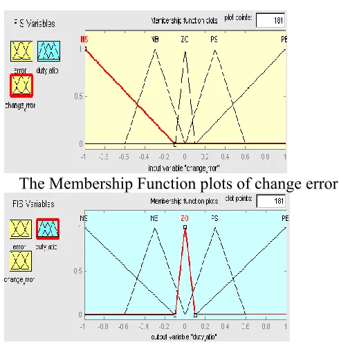
The dc-dc converter is a nonlinear function of the duty cycle because of the small signal model and its control method was applied to the control of boost converters. Fuzzy controllers do not require an exact mathematical model. Instead, they are designed based on general knowledge of the plant. Fuzzy controllers are designed to adapt to varying operating points. Fuzzy Logic Controller is designed to control the output of boost dc-dc converter using Mamdani style fuzzy inference system. Two input variables, error (e) and change of error (de) are used in this fuzzy logic system. The single output variable (u) is duty cycle of PWM output.
The Membership Function plots of change error
The Membership Function plots of duty ratio Fuzzy Logic Rules:
The objective of this dissertation is to control the output voltage of the boost converter. The error and change of error of the output voltage will be the inputs of fuzzy logic controller. These 2 inputs are divided into five groups; NB: Negative Big, NS: Negative Small, ZO: Zero Area, PS: Positive small and PB: Positive Big and its parameter. These fuzzy control rules for error and change of error can be referred in the table that is shown in Table I as per below:
The Membership Function plots of error Table I
Available online: https://edupediapublications.org/journals/index.php/IJR/ P a g e | 3874
V. MATLAB/SIMULINK
RESULTS
Fig.8 Matlab/Simulink circuit for DSTATCOM model of Three Phase four Wire System
Fig.9 Output waveform of Supply voltage
Fig.10 Output waveform of Supply current
Fig.11 Output waveform of Load current
Fig.12 Output waveform of DC link voltage
Available online: https://edupediapublications.org/journals/index.php/IJR/ P a g e | 3875
Fig.14 Output waveform of Active power at load side
Fig.15 Output waveform of Active power
Fig.16 Output waveform of reactive power at supply side
Fig.17 Output waveform of reactive power at supply side
Fig.18 Output waveform of reactive power
Available online: https://edupediapublications.org/journals/index.php/IJR/ P a g e | 3876
Fig.19 THD of supply current (a) before compensation (b) after compensation
Fig.20 THD of Source current with fuzzy
VI. CONCLUSION
The proposed fuzzy logic controller based multilevel inverter (MLI) and distributed static synchronous compensator (DSTATCOM) is proposed in this paper to improve the Power Quality by reducing harmonics in source current. Fuzzy Logic Control based DSTATCOM is used to compensate harmonics, produced in this case of a non-linear loads. The
THD value is measured for different cases. The Fuzzy Logic Controller based DSTATCOM demonstrates a better dynamic behavior than conventional methods. Therefore, the fuzzy logic controller based MLI and DSTATCOM can improve the power quality by considerably reducing THD.
REFERENCES
[1] Grino R, Cardoner R, Costa-Castello R,
and Fossas E. Digital repetitive control of a three- phase four-wire shunt active filter. IEEE Transactions on Industrial Electronics; 2007; vol. 54, no. 3, pp. 1495-1503.
[2] Satyanarayana, G.; Ganesh, K.Lakshmi;
Kumar, Ch. Narendra; Krishna, M. Vijaya, "A critical evaluation of power quality features using Hybrid Multi- Filter Conditioner topology," Green Computing, Communication and Conservation of Energy (ICGCE), 2013 International Conference on , vol., no., pp.731,736, 12-14 Dec. 2013.
[3] Hirve S, Chatterjee K, Fernandes BG,
Imayavaramban M, and Dwari S. PLL-less active power filter based on one cycle control for compensating unbalanced loads in three phase four-wire system. IEEE Transactions on Power Delivery; 2007; vol. 22, no. 4, pp. 2457- 2465.
[4] G. Satyanarayana., K.N.V Prasad, G.
Ranjith Kumar, K. Lakshmi Ganesh, "Improvement of power quality by using hybrid fuzzy controlled based IPQC at various load conditions," Energy Efficient Technologies for Sustainability (ICEETS), 2013 International Conference on , vol., no., pp.1243,1250, 10-12 April 2013.
[5] Al-Haddad K. Power quality issues under
Available online: https://edupediapublications.org/journals/index.php/IJR/ P a g e | 3877
[6] Abdalla, I.I.; Rao, K.S.R.; Perumal,
N.; , "Harmonics mitigation and power factor correction with a modern three phase four-leg shunt active power filter," 2010 IEEE International Conference on Power and Energy (PECon), vol., no., pp.156-161, Nov. 29 2010-
Dec. 1 2010
[7] Babaei E, Hosseini SH, and
Gharehpetian GB. A new topology for multilevel current source converters. ECTI IEEE Transactions
on Electric Engineering, Electronic and
communications, vol. 4, no. 1, pp. 2-12, Feb. 2006.
[8] Rodriguez J, Bernet S, Wu B, Pontt
JO, and Kouro S. Multilevel voltage source- converter topologies for industrial medium-voltage drives. IEEE Transactions on Industrial Electronics, vol. 54, no. 6, pp. 2930-2945, Dec. 2007.
[9] Bernet S, “Recent developments of
high power converters for industry and traction applications. IEEE Transactions on Power Electronics, vol. 15, no. 6, pp. 1102- 1117, Nov. 2000.
[10] Ghoreishy H, Varjani AY, Farhangi
S, and Mohamadian M. A novel pulse-width and amplitude ISSN (Online): Applied modulation (PWAM) control strategy for power converters. Journal of Power Electronic, vol. 10, no. 4, pp. 374-381, Jul. 2010.
[11] Lai J-S and Peng FZ. Multilevel
converters-a new breed of power converters. IEEE Transactions on Industrial Application, vol. 32, no. 3, pp. 509-517, May/Jun. 1996.
[12] Peng FZ, McKeever JW, and
Adams DJ. A power line conditioner using cascade multilevel inverters for distribution systems. IEEE Transactions on Industrial Application, vol. 34, no. 6, pp. 1293-1298, Nov/Dec. 1998.
[13] G. Satya Narayana, Ch. Narendra
Kumar, Ch. Rambabu “ A Comparative Analysis of PI Controller and Fuzzy Logic Controller for Hybrid Active Power Filter Using Dual
Instantaneous Power Theory” International Journal of Engineering Research & Development, Vol-4, Issue-6, p.p. 29-39, Oct, 2012..
[14] Izzeldin, I. A.; Rama Rao, K.S.; Perumal,
N.; , "Seven level cascaded inverter based shunt active power filter in four-wire distribution system," 2011 IEEE Ninth International Conference on Power Electronics and Drive Systems (PEDS), vol., no., pp.676- 681, 5-8 Dec. 2011
[15] Silva LA, Pimentel SP, and Pomilio J A.
Nineteen level active filter system using asymmetrical cascaded converter with DC voltages control. 2005 IEE 36th Power Electronic Specialists
Conf., (PESC); pp. 303-