Optimization of Semi-Active
Control of Seismically Excited
Buildings Using Genetic Algorithms
S. Pourzeynali
1;and T. Mousanejad
1Abstract. In this paper, the performance of semi-active viscous dampers in reducing the response of tall buildings to earthquake acceleration is optimized using genetic algorithms. Torsional eects due to irregularities exist in the building and due to unsymmetrical placement of the dampers are taken into account through 3-D modeling of the building. For the numerical example, a twelve-story building is chosen. The building is modeled as a 3-D frame. The equations of motion of the building with semi-active viscous dampers, subjected to earthquake acceleration, is written, resolved in state space and the results are compared with those of the uncontrolled building. Moreover, in order to minimize building responses such as top story displacement and base shear, the required number and location of dampers are optimized using genetic algorithms.
Keywords: Optimization; Genetic algorithms; Fluid viscous damper; Semi-active control.
INTRODUCTION
A large amount of energy is imported into a struc-ture during earthquake ground motion. Conventional design philosophy prevents collapse by allowing struc-tural members to absorb and dissipate the transmitted earthquake energy using inelastic cyclic deformations in specially detailed regions. Consequently, depending on the extent of the design, damage to parts or all of the structure may occur, possibly such that the structure is no longer repairable.
During the last decades, many control systems have been developed to enhance safety and reduce damage to structures during earthquakes [1-3]. These alternative approaches aim to control the structural seismic response and energy dissipation demand on the structural members by modifying the dynamic properties of the system.
Many research studies have shown that the con-trol systems are highly eective in reducing the re-sponse of structures subjected to earthquake excita-tions. Three main categories of these control systems are passive, semi-active and active devices. Various
1. Department of Civil Engineering, Faculty of Engineering, University of Guilan, Rasht, P.O. Box 41635-3756, Iran. *. Corresponding author. E-mail: [email protected] Received 15 May 2009; received in revised form 30 August 2009; accepted 30 November 2009
types of control system have been developed and experimentally veried. A number of them have been implemented in full scale civil structures [4].
Among these control systems, semi-active control has received considerable attention from the civil engi-neering community in recent years [5-8], because it has the adaptability of active control devices without the need of large input energy as well as the reliability of passive devices. Preliminary analytical and experimen-tal studies indicate that appropriately implemented semi-active systems perform signicantly better than passive devices [9-12] and have the potential to achieve or even surpass the performance of fully active sys-tems [13].
By using a small external power, a semi-active device dynamically changes parameters, such as either damping or stiness coecients, and produces a large control force [14]. Control forces are developed based on feedback from sensors that measure the excitation and/or the response of the structure [15].
To date, many variable semi-active structural con-trol systems have been proposed and some have been implemented in real structures. Examples include vari-able stiness devices, Electrorheological (ER) dampers, Magnetorheological (MR) dampers, semi-active uid viscous dampers, semi-active tuned mass dampers, and semi-active tuned liquid dampers. Among these devices, the use of semi-active uid viscous dampers is
considered to be a reliable strategy for enhancing the seismic performance of building structures.
In this paper, the performance of semi-active uid viscous dampers in reducing the response of buildings to earthquake excitations is optimized using genetic algorithms. For this purpose, the building is modeled as a 3-D frame and, then, by employing an analytical procedure, the equations of motion of the building with added semi-active uid viscous dampers are written. Torsional eects due to irregularities exist in the build-ing and due to the unsymmetrical placement of the dampers are taken into account through 3-D modeling of the building. The viscous dampers are modeled by a linear spring-dashpot connected in parallel. Then, employing a state-space model and a Linear Quadratic Regulator (LQR) control algorithm, the responses of a semi-actively controlled building are obtained.
Furthermore, it is quite important to know that damper conguration can have a signicant eect on the structural response to earthquake excitations. For many building structures, the optimal conguration of dampers may provide considerable performance improvement or cost saving. So, in this paper, Genetic Algorithms (GAs) are used to nd the optimal number and distribution of semi-active uid viscous dampers in the model of the building to minimize building responses such as top story displacement, acceleration and base story shear force. For numerical study, a 12-story building located in the city of Rasht, in Iran, is chosen.
ASSUMPTIONS
The following simplied assumptions are made in this study:
a. The building is assumed to have linear behavior during earthquake excitation and therefore, no material nonlinearity is considered in the analyses; b. All oors of the building are assumed to be rigid in
plane and exible for out of plane-bending;
c. The building is modeled as a 3-D frame structure, having two lateral and one rotational degree(s) of freedom in the mass center of each oor;
d. The structure is analyzed under two horizontal components of the earthquake ground motion, si-multaneously;
e. The behavior of the uid viscous damper is assumed to be linear.
SEMI-ACTIVE FLUID VISCOUS DAMPER The force-velocity relationship for a uid viscous damper is represented as:
F = CVn; (1)
where F is the damping output force; V is the relative velocity of the piston head; C is damping constant co-ecient; and n is a constant exponent, which depends upon the shape of the piston head. The value of n is usually between 0.3 and 1.0 [16].
Passive uid viscous dampers were installed in the newly-constructed San Bernardino County Medical Center in California as components in the rubber bearing, seismic isolation system [17].
A semi-active uid damper can be achieved by adding an external bypass loop, which contains a controllable valve, to a passive uid damper. The con-cept of applying this kind of variable-damping device to control the motion of bridges experiencing seismic motion was rst introduced by Feng and Shinozuka [18] and Kawashima et al. [19]. The behavior of the semi-active uid damper is essentially similar to a passive uid damper, except that the semi-active uid damper has an external valve that connects two sides of the cylinder and modulates the output force. The output force is described by [20]:
F = C(t)Vn; (2)
where C(t) is the damping time-varying coecient. The maximum capacity (force F ) of the dampers used in this study is limited to 1000 kN.
In this kind of damper, an adjustable damping property makes it capable of generating a wide range of damping forces. Since this is a small power or source just used for closing or opening the external valve, it can produce a very large damping force without the need of large input energy and can, therefore, operate on batteries. Shaking table tests indicate that this type of semi-active device can signicantly increase the energy dissipation capability of structures with low damping [21].
The rst full implementation of a semi-active uid viscous damper was on the Walnut Creek Bridge on Interstate Highway I-35, in Oklahoma, in order to reduce vehicle-induced vibrations [22]. A similar device has also been studied by Constantinou and Symans [23]. Also, Kurata et al. installed full-scale semi-active uid viscous dampers in a ve-story steel structure in the Kajima, Shizuoka building in Shizuoka, Japan. More recently, these dampers have been installed in some new buildings in the Tokyo Siodome area [24]. Response analysis has shown that this system can signicantly reduce both story shear forces and drifts [14].
SEMI-ACTIVE CONTROL OF BUILDINGS WITH FLUID VISCOUS DAMPERS
In this paper, the response analysis of a three di-mensional (3-D) model of multi-story buildings with
added semi-active uid viscous dampers is studied. Therefore, torsional eects due to irregularities exist in the building and due to unsymmetrical placement of the added dampers can be taken into account.
For buildings subjected to multi-component earthquake excitations, the equation of motion (with-out any damper) is represented as [25]:
M U + C _U + KU = Ml Ug(t); (3a)
Ug(t) =
8 < :
ugx(t)
ugy(t)
0 9 =
; ; (3b)
where M, K, and C are structural mass, stiness, and damping matrices, respectively; U, _U, and U are displacement, velocity and acceleration vectors; l is the N Ng inuence matrix; ugx and ugy are earthquake
ground accelerations in x and y directions, respectively; and N and Ng are the number of DOFs of the
super-structure and support-excitation components, respec-tively.
Semi-active uid viscous dampers can be designed for both new and existing buildings. They are installed between oors in connection with diagonal members or tied into chevron braces. In the present study, dampers are placed in diagonal braces.
The dynamic behavior of these kinds of damper can be expressed by a variable damping coecient, C(t), and an elastic spring in parallel. Their behavior is represented by considering two degrees of freedom per node in the global coordinates (Figure 1a) [26], and by assuming the oors are to be rigid. When the jth semi-active uid viscous damper is connected with a
diagonal brace between (i 1)th and ith oors on a x z plane, its lateral displacement on the ith oor and in the x direction can be represented as (Figure 1b):
(ujx)i= (eyj)i(u)i+ (ux)i; (4)
where (eyj)i is the oset of the jth damper from the
mass-center of the ith oor in a x direction; (ux)i and
(u)i are the lateral displacement in x direction and
rotational displacement about the z axis, both for the mass-center of the ith oor, respectively. For a damper placed on the y z plane, Equation 4 is to be changed to:
(ujy)i= (exj)i(u)i+ (uy)i; (5)
where (exj)i is the oset of the jth damper from the
mass-center of the ith oor in the y direction; (uy)iand
(u)iare the lateral displacement in the y direction and
rotational displacement about the z axis, both for the mass-center of the ith oor, respectively.
Based on Equations 4 and 5 and condensing vertical degrees of freedom, the time-varying damping matrix, CDj(t), of the jth damper placed on the x z
plane can be written as: CDj(t) = cdj(t)
2 6 6 4
cos2 cos2
cos2 cos2
(eyj)i 1cos2 (eyj)i 1cos2
(eyj)icos2 (eyj)icos2
(eyj)i 1cos2 (eyj)icos2
(eyj)i 1cos2 (eyj)icos2
(eyj)2i 1cos2 (eyj)i(eyj)i 1cos2
(eyj)i 1(eyj)icos2 (eyj)2icos2
3 7 7 5 ;
(6)
where cdj(t) is the variable damping coecient of the
jth damper, and is the angle of the damper with a horizontal axis. It is noted that the CDj(t) matrix
is written on the basis of the super-structure, mass-center degrees of freedom (DOFs); (ux)i 1, (u)i 1,
(ux)i, (u)i (refer to Figure 1b).
Then, by assembling the condensed matrix of each damper into the total structural damping matrix of the building, the equation of motion of the building with added uid viscous dampers can be obtained. By using this method, when damper j is added to a diagonal brace of the building, between (i 1)th and ith oors on the x z plane, time-varying damping forces produced in lateral and rotational degrees of freedom of (i 1)th and ith oors, respectively, can be evaluated as:
(fx)i 1= cdj(t) cos2[( _ux)i 1 ( _ux)i
+ (eyj)i 1( _u)i 1 (eyj)i( _u)i]; (7a)
(fx)i = cdj(t) cos2[ ( _ux)i 1+ ( _ux)i
(eyj)i 1( _u)i 1+ (eyj)i( _u)i]; (7b)
(f)i 1= cdj(t) cos2[(eyj)i 1( _ux)i 1
(eyj)i 1( _ux)i+ (eyj)2i 1( _u)i 1
(eyj)i(eyj)i 1( _u)i]; (7c)
(f)i= cdj(t) cos2[ (eyj)i( _ux)i 1+ (eyj)i( _ux)i
(eyj)i 1(eyj)i( _u)i 1+ (eyj)2i( _u)i]: (7d)
So, the equation of motion of the building with one added damper can be expressed as:
M U+C _U+ 8 > > > > > > > > > > > > > > > > > > > > > > > < > > > > > > > > > > > > > > > > > > > > > > > : 0 ... 0 ( 1)i 1
(+1)i
0 ... 0 (ey)i 1
(ey)i
0 ... 0 9 > > > > > > > > > > > > > > > > > > > > > > > = > > > > > > > > > > > > > > > > > > > > > > > ; 3n1
fj+KU= Ml Ug(t);
(8)
where fj is the damping force of the jth damper
installed in a diagonal brace with the angle of to the horizontal axis and dened in Equation 7b.
Equation 8 can also be written as:
M U + C _U + KU = dfj Ml Ug(t); (9)
where d is implicitly given in Equation 8.
Equation 9 relates to the case when only one damper, j, is added to the building. The generalized form of this equation, when m and k dampers are used in x and y directions, respectively, is represented as:
M U + C _U + KU = DF Ml Ug(t); (10)
where matrix D is obtained according to the numbers and placement of the dampers and represented as [27]:
D = 2 6 6 6 6 6 6 6 6 6 6 6 6 6 6 6 6 6 6 6 6 6 6 6 6 6 6 6 6 6 6 6 6 6 6 6 6 6 6 6 6 6 6 6 6 6 6 6 6 6 4 1 0
0 ...
..
. 1 ...
1
0 1
..
. 1 0
1 0 .. . .. . 0
(ey1)1 0 0 (ex1)1
0 ... ... 0
..
. (eyj)i 1 0 ...
(eyj)i ...
0 ..
. (eym)11
0 0 (eym)12 0
0 .. . 0 0 0 1 ... 1 0 1 1
0 0
.. . (exj)i 1
(exj)i ...
0 ..
. (exk)11
0 (exk)12
3 7 7 7 7 7 7 7 7 7 7 7 7 7 7 7 7 7 7 7 7 7 7 7 7 7 7 7 7 7 7 7 7 7 7 7 7 7 7 7 7 5 3N(m+k) ; (11)
dampers, given as: F = 8 > > > > > > > > > > > > > > > > < > > > > > > > > > > > > > > > > : fx;1 fx;2 ... fx;m 1
fx;m
fy;1
fy;2
... fy;k 1
fy;k 9 > > > > > > > > > > > > > > > > = > > > > > > > > > > > > > > > > ; (m+k)1 : (12)
In order to solve Equation 10, it is written in state-space form as:
_Z = AZ + HF + BW; (13)
where A is the state matrix; F is the time-varying damping control force vector; Z is the space vector; and W is the disturbance vector. Variables in this equation are dened in the following:
A =
0 I
M 1K M 1C
; B =
0 I
; W = l Ug(t); Z =
U _U ; H = 0 M 1D
; (14)
where 0 is a zero matrix, and I is an identity matrix. In the semi-active control of the buildings, damp-ing forces are produced based on feedback from sensors that measure the excitations/response of the structure, and with a damping command from the computer [15]. In this study, the Linear Quadratic Regulator (LQR) control algorithm is used to design the damping command. In this algorithm, the control force is found, such that the performance index, J, is minimized [14]:
J =
1
Z
0
(ZTQZ + FTRF)dt; (15)
where: Q =
Qv 0
0 0
; Qv= diag(1);
R = 10 qdiag(1); (16)
where q is a weighting coecient and should be cal-culated for the building. In the numerical analysis, it is shown that by increasing the value of q, the responses of the building decrease, while the damping
force increases. Since the maximum capacity of the dampers used in this study is limited to 1000 kN, the optimal value of q should be obtained.
The minimization of the performance index, J, results in a control force vector of [14]:
F = R 1BTPZ = GZ;
G = R 1BTP =G
d Gv; (17)
in which matrix G is a feed-back gain, full matrix, with respect to the displacement and velocity. But, since the gain with respect to the displacement is negligible, velocity feed-back control is adapted and, therefore Gd= 0 [14].
Also, P is the solution of the algebraic Riccati equation shown as [14]:
PA + ATP + Q PBR 1BTP = 0: (18)
Substituting Equation 17 into Equation 13, the state-space equation is written as:
_Z = (A HG)Z + BW: (19)
GENETIC ALGORITHMS
Genetic Algorithms (GAs), rst proposed by Hol-land [28], are very eective and powerful stochastic search engines, based on the mechanism of natural selection and natural genetics processes that drive bio-logical evolution. They can be used for solving a variety of optimization problems that are not well suited for standard optimization algorithms including problems in which the objective function is discontinuous, non-dierentiable, stochastic or highly nonlinear.
In civil engineering design, especially in designing complex structures, optimization has a special impor-tance and value. Basically, the optimization process nds a set of quantities for design parameters that yield optimal values of objective functions. Most optimiza-tion methods used in the design of structural vibraoptimiza-tion control systems are traditional, gradient-based search techniques. However, for these techniques, there are diculties, both in selecting a suitable continuously dierentiable cost function as well as incorporating the nonlinearities involved in the problem. Compared to these gradient-based methods, Genetic Algorithms (GAs) are very simple and powerful optimal search techniques, because GAs do not need a continuous and dierentiable function to solve the problem, and are able to take into account the nonlinearities (if any) of the problem [29].
The genetic algorithms start from an initial popu-lation of individuals and repeatedly modify them. Each individual in the population is called a chromosome, representing a possible solution to a given problem.
Each chromosome is assigned a tness score, according to how good a solution to the problem it is [30]. At each generation, GAs select highly t individuals at random from the current population to be parents and uses them to produce the children for the next generation. Over successive generations, the population evolves toward an optimal solution.
The GAs use three main operations to create the next generation from the current population: selec-tive reproduction, crossover, and mutation. In every generation, a set of strings is selected into the mating pool, based on its relatives' tness. The tter strings are given a better chance of passing their genes into the next generation. This process of natural selection is operated by selective reproduction. The crossover operation combines two parents and changes their genes to form new strings for the next generation. The mutation operation also applies random changes to the selected genes in the new generation [31].
The crossover operation used here is a one-cut-point, which randomly selects the cut point and ex-changes the right parts of the parents to generate new strings. The probability of crossover is set as Pc = 0:25;
thus, in average 25% of chromosomes undergo the crossover process.
Mutation alerts one or more genes with a proba-bility equal to the mutation rate. In this study, the probability of mutation is set as Pm = 0:01; thus,
in average 1% of all bits of the population undergoes mutation.
NUMERICAL STUDY
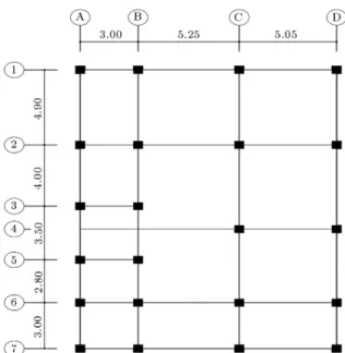
In this study, for investigating the performance of semi-active uid viscous dampers on the control of civil engineering structures subjected to earthquake excitations, a realistic 12-story building located in the city of Rasht, in Iran, is considered as a numerical problem. A typical oor plan of this building is shown in Figure 2. This building is a steel structure with braced frame systems and its height is about 33.0 m.
For this building, the mass and stiness matrices are calculated using the matrix analysis procedure. The damping matrix of the building is also constructed from a linear combination of the mass and stiness
Figure 2. Typical oor plan of the building outline.
matrices (Rayleigh method). To calculate the propor-tionality coecients, modal damping ratios of the rst and middle modes are assumed to be about 5% of the critical values.
The building is analyzed for 15 earthquake ac-celeration records. Among these, 5 accelerograms are selected and scaled, according to the International Building Code (IBC) 2006 [32] for the design of seismic resistant buildings, and used for time history analysis of the building. More details of the 5 scaled accelerograms are given in Table 1.
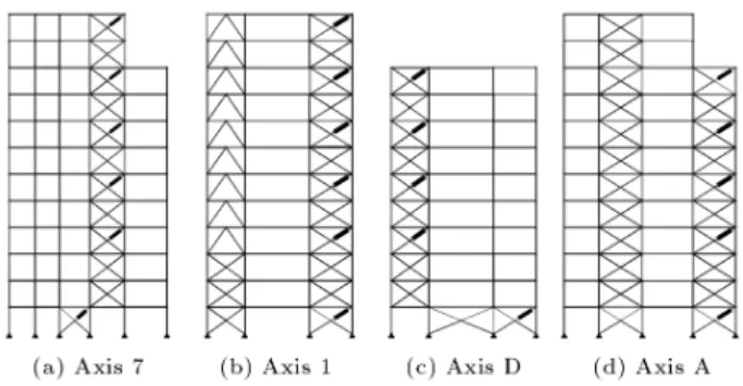
First, by considering 22 semi-active uid viscous dampers, the building is analyzed for the 5 scaled records. Figure 3 shows the placement of these dampers throughout the building. Dynamic charac-teristics of these dampers are given in Table 2 [14].
For determining the weighting coecient, q, in the LQR control algorithm (Equation 16), q is varied from 4 to 10 and the maximum values of acceleration, displacement, story shear, and damping force are calculated for ve selected values of q over the above range (Figure 4). The results show that by increasing values of q, the responses of the structure decrease but the damping force increases (Figure 4). So, because of limitation in the damping force (Table 2), q = 9 is chosen in this analysis as the optimal value of q.
Table 1. Five acceleration records used for time history analysis.
Earthquake Date Station Magnitude (Ms) PGA (g) Duration (sec) Data Source Northridge, California 1994/01/17 Montebello 6.7 0.128 21.82 USC Chi-Chi, Taiwan 1999/09/20 CHY041 7.6 0.639 90.0 CWB Imperial Valley, California 1979/10/15 El Centro 6.9 0.221 39.54 USGS Kocaeli, Turkey 1999/08/17 Ambarli 7.8 0.249 150.39 CWB Manjil, Iran 1990/06/20 Roudsar 7.7 0.093 21.88 NEIS
Figure 3. Conguration of dampers.
Table 2. Characteristics of the dampers [7]. Maximum Damping Force 1000 KN Maximum Damping Coecint 200 KN sec/mm Minimum Damping Coecint 1 KN sec/mm Weight of Damper 1300 kg
By considering the above value for q and using MATLAB software, the equation of motion of the building with dampers is resolved and the maximum responses of the building are calculated for the ve scaled earthquake acceleration records.
According to the standard IBC 2006 [32], in a time history analysis, if the number of earthquake acceleration records is less than 7, the maximum
response of the building is to be chosen as the building response. Maximum responses of the building for ve scaled earthquake accelerations are shown in Figure 5. As seen from the gure, displacements of the building are considerably reduced. In this case, the maximum reduction of top story displacement, acceleration and base shear force are about 63%, 38% and 40%, re-spectively. So, it is seen that semi-active uid viscous dampers are very eective in reducing the building's seismic responses.
Eect of Placement of Dampers on the Building's Responses
For investigating the eect of damper placement on building responses, 22 dampers are placed in 3 dierent locations in the building, as follows:
a. All dampers are monotonically distributed in the height of the building (Figure 3);
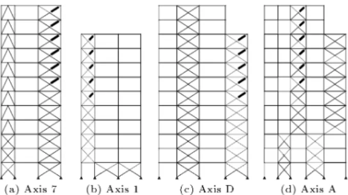
b. All dampers are placed in the upper oors of the building (Figure 6);
c. All dampers are placed in the lower oors of the building (Figure 7).
The building is analyzed for ve scaled earthquake accelerations for the above three cases. In Figure 8, the maximum responses of the building for the Northridge
Figure 5. Maximum response of the building for ve scaled earthquake accelerations.
Figure 6. Conguration of dampers for case III.
Figure 7. Conguration of dampers for case IV.
earthquake are shown. The results show that maxi-mum displacement responses of the building are more sensitive to the location of the dampers, while the story shear forces are less sensitive to this parameter. Therefore, in order to study further the eect of this parameter on building responses, the location of the dampers is optimized in the next section, using genetic algorithms.
Optimization of the Location and Number of Dampers Using Genetic Algorithms
In this section, using genetic algorithms, the required number and location of dampers are optimized to mini-mize the building's top story displacement, acceleration and base shear force.
In the example building, braces are located in axes 1, 2, 4, 5, 7, A, B, and D. Among these axes, those placed far from the center of mass are more proper for placing dampers, because, according to Equations 7a and 7b, damping force is directly related to ex or ey,
and by increasing the values of ex or ey the amount
of damping force increases. Thus, axes 1, 7, A and D are selected for placing the dampers and, therefore, 44 positions are available for this purpose. In order to model the location and number of dampers in the GA procedure, a variable X(i) is considered to show the presence of a damper in location i (Figure 9). X(i) is 1 when a damper is placed at location i, otherwise, X(i) is 0. The values of X(i) make a location matrix, L [27].
Figure 8. Maximum responses of the building in the Northridge earthquake for dierent location of dampers.
Figure 9. Assigned variables X(i) to the position of dampers.
The objective function is represented as: g = min
2 6 4
umax;c
umax;u 100 50
umax;c
umax;u 100 65
Vmax;c
Vmax;u 100 65
3 7 5
max
; (20)
in which umax and umax are the building's top story
maximum displacement and acceleration, respectively; Vmaxis the maximum base shear; and subscripts c and
u denote the controlled and uncontrolled values. In dening the objective function, it is assumed that the upper limit of the reduction factors (ratio of controlled
to uncontrolled responses) for the maximum displace-ment, acceleration, and base shear of the building are to be about 50%, 65% and 65%, respectively.
According to above denition, and using the GA procedure, the optimized conguration of dampers is determined for 15 dierent earthquake acceleration records, mentioned in previous sections. It should be noted that for the GA optimizer, the following parameters are chosen:
Number of chromosomes = 50, Number of generations = 300,
Probability of crossover, Pc= 0:25
Probability of mutation, Pm= 0:01.
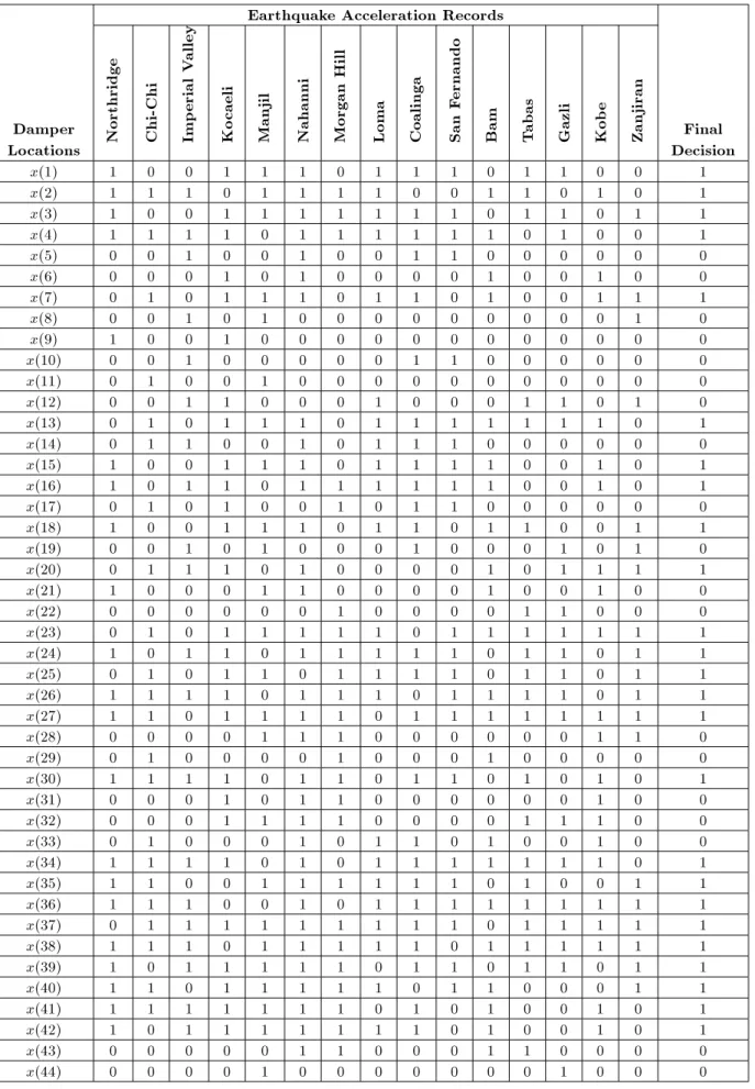
In Figure 10, the performance of the GA is shown for the Coalinga earthquake. According to the results obtained for the previously mentioned 15 earthquakes, the optimized location and number of dampers are obtained. The GA is performed for one earthquake acceleration record at each time, and the results of the location of the dampers, for all 15 acceleration records, are shown in Table 3. In this table, for a given earthquake acceleration, `1' indicates the presence of a damper at location X(i), otherwise no damper is considered at that location. The nal decision for damper placement is made based on the results of Table 3. For any location, if the number of 1 is more than 0, then one damper is considered at that location, otherwise no damper is chosen for that location.
Finally, based on the above procedure, 25 dampers are selected in optimal locations, and shown in Figure 11.
Moreover, in order to show the eectiveness of
Figure 10. Performance of GA for Coalinga earthquake.
Figure 11. Optimized location of dampers using GA optimizer.
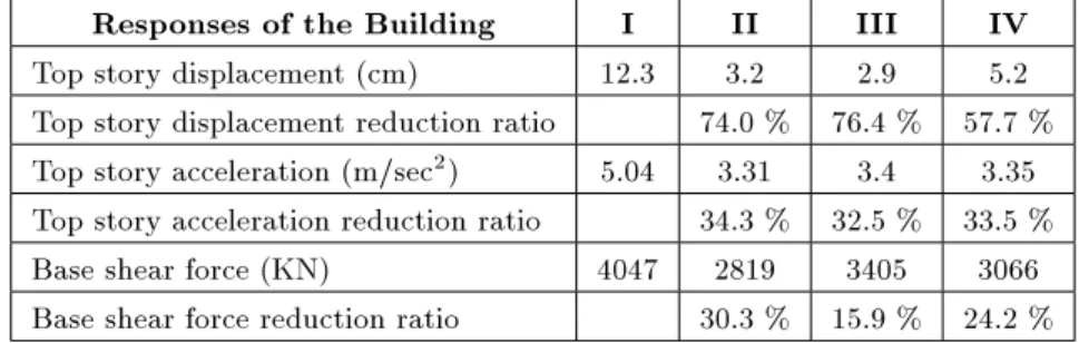
the optimized number and location of dampers, av-erage values for the building's top story maximum displacement, acceleration and base shear force for the 15 earthquake accelerations are calculated for the following 4 cases and compared in Table 4:
I. There are no dampers on the building (uncon-trolled response);
II. The building is controlled with 25 dampers all placed in their optimal positions (Figure 11); III. The building is controlled with 22 dampers all
placed in the upper oors of the building (Fig-ure 6);
IV. The building is controlled with 22 dampers all placed in the lower oors of the building (Fig-ure 7).
The results show that although, in point of top story displacement view, case III is more eective, it is not able to reduce the base shear force eectively. By comparing the results given in Table 4, it can be concluded that case II, in which the number and location of dampers are optimized using the GA, is in general more eective in reducing building responses. CONCLUSIONS
In this paper, the performance of semi-active uid viscous dampers on the reduction of seismic responses of building structures is optimized using genetic algo-rithms. For this purpose, a realistic 12-story building located in the city of Rash, in Iran, is considered as a numerical problem. Equations of motion of a three-dimensional (3-D) model of the building, with added semi-active uid viscous dampers, are written using an analytical procedure. Semi-active dampers are modeled by a linear spring-dashpot connected in parallel. For time history analysis of the building, 5 earthquake acceleration records are chosen, corrected for base-line errors, ltered for unwanted noise, and scaled based on the IBC 2006 standard. Then, using MATLAB software, the equations are resolved in state-space and the controlled and uncontrolled responses of the building are obtained.
Moreover, using genetic algorithms, the required number and location of dampers are optimized to minimize buildings' responses such as top story dis-placement, acceleration and base shear force. From the results of numerical study, it is found that: 1. Semi-active uid viscous dampers are very eective
in reducing the building's seismic responses. For the example building, a reduction of 74% is obtained on building a top story horizontal displacement. 2. In the LQR control algorithm, by increasing
Table 3. Results of GA performance for damper locations for 15 earthquake acceleration records. Earthquake Acceleration Records
Damper
Locations Northridge Chi-Chi Imp
erial
V
alley
Ko
caeli
Manjil Nahanni Morgan
Hill
Loma Coalinga San
Fernando
Bam Tabas Gazli Kob
e
Zanjiran Final Decision x(1) 1 0 0 1 1 1 0 1 1 1 0 1 1 0 0 1 x(2) 1 1 1 0 1 1 1 1 0 0 1 1 0 1 0 1 x(3) 1 0 0 1 1 1 1 1 1 1 0 1 1 0 1 1 x(4) 1 1 1 1 0 1 1 1 1 1 1 0 1 0 0 1 x(5) 0 0 1 0 0 1 0 0 1 1 0 0 0 0 0 0 x(6) 0 0 0 1 0 1 0 0 0 0 1 0 0 1 0 0 x(7) 0 1 0 1 1 1 0 1 1 0 1 0 0 1 1 1 x(8) 0 0 1 0 1 0 0 0 0 0 0 0 0 0 1 0 x(9) 1 0 0 1 0 0 0 0 0 0 0 0 0 0 0 0 x(10) 0 0 1 0 0 0 0 0 1 1 0 0 0 0 0 0 x(11) 0 1 0 0 1 0 0 0 0 0 0 0 0 0 0 0 x(12) 0 0 1 1 0 0 0 1 0 0 0 1 1 0 1 0 x(13) 0 1 0 1 1 1 0 1 1 1 1 1 1 1 0 1 x(14) 0 1 1 0 0 1 0 1 1 1 0 0 0 0 0 0 x(15) 1 0 0 1 1 1 0 1 1 1 1 0 0 1 0 1 x(16) 1 0 1 1 0 1 1 1 1 1 1 0 0 1 0 1 x(17) 0 1 0 1 0 0 1 0 1 1 0 0 0 0 0 0 x(18) 1 0 0 1 1 1 0 1 1 0 1 1 0 0 1 1 x(19) 0 0 1 0 1 0 0 0 1 0 0 0 1 0 1 0 x(20) 0 1 1 1 0 1 0 0 0 0 1 0 1 1 1 1 x(21) 1 0 0 0 1 1 0 0 0 0 1 0 0 1 0 0 x(22) 0 0 0 0 0 0 1 0 0 0 0 1 1 0 0 0 x(23) 0 1 0 1 1 1 1 1 0 1 1 1 1 1 1 1 x(24) 1 0 1 1 0 1 1 1 1 1 0 1 1 0 1 1 x(25) 0 1 0 1 1 0 1 1 1 1 0 1 1 0 1 1 x(26) 1 1 1 1 0 1 1 1 0 1 1 1 1 0 1 1 x(27) 1 1 0 1 1 1 1 0 1 1 1 1 1 1 1 1 x(28) 0 0 0 0 1 1 1 0 0 0 0 0 0 1 1 0 x(29) 0 1 0 0 0 0 1 0 0 0 1 0 0 0 0 0 x(30) 1 1 1 1 0 1 1 0 1 1 0 1 0 1 0 1 x(31) 0 0 0 1 0 1 1 0 0 0 0 0 0 1 0 0 x(32) 0 0 0 1 1 1 1 0 0 0 0 1 1 1 0 0 x(33) 0 1 0 0 0 1 0 1 1 0 1 0 0 1 0 0 x(34) 1 1 1 1 0 1 0 1 1 1 1 1 1 1 0 1 x(35) 1 1 0 0 1 1 1 1 1 1 0 1 0 0 1 1 x(36) 1 1 1 0 0 1 0 1 1 1 1 1 1 1 1 1 x(37) 0 1 1 1 1 1 1 1 1 1 0 1 1 1 1 1 x(38) 1 1 1 0 1 1 1 1 1 0 1 1 1 1 1 1 x(39) 1 0 1 1 1 1 1 0 1 1 0 1 1 0 1 1 x(40) 1 1 0 1 1 1 1 1 0 1 1 0 0 0 1 1 x(41) 1 1 1 1 1 1 1 0 1 0 1 0 0 1 0 1 x(42) 1 0 1 1 1 1 1 1 1 0 1 0 0 1 0 1 x(43) 0 0 0 0 0 1 1 0 0 0 1 1 0 0 0 0 x(44) 0 0 0 0 1 0 0 0 0 0 0 0 1 0 0 0
Table 4. Responses of the building and their reduction ratio for four cases. Responses of the Building I II III IV Top story displacement (cm) 12.3 3.2 2.9 5.2 Top story displacement reduction ratio 74.0 % 76.4 % 57.7 % Top story acceleration (m/sec2) 5.04 3.31 3.4 3.35
Top story acceleration reduction ratio 34.3 % 32.5 % 33.5 % Base shear force (KN) 4047 2819 3405 3066 Base shear force reduction ratio 30.3 % 15.9 % 24.2 %
decrease, while the damping force increases. Due to the upper limitation of the damping force, q cannot be chosen as more than a specic value. For the example building, q is obtained to be about 9. 3. The location of dampers can have a signicant eect
on the response of the structures. Placing the dampers in the upper oors of the building eec-tively reduces the building's top story displacement, but they are not able to further reduce the base shear force by much. As well, placing the dampers in the lower oors of the building eectively reduces the base shear force, but does not have much eect on reduction of the building top story displace-ments. Therefore, the optimal number and location of the dampers can be evaluated using the GA to simultaneously reduce both the building's top story displacement and base shear force.
REFERENCES
1. Joghataie, A. and Asbmarz, M.M. \Design method and feasibility study of fully actively controlled frames", Scientia Iranica, 11(1&2), pp. 50-59 (2004).
2. Ggannadi-Asl, A. and Zahrai, S.M. \Seismic perfor-mance of TMDs in improving the response of MRF buildings", Scientia Iranica, 15(1), pp. 21-33 (2008). 3. Kavand, A. and Zahrai, S.M. \Strong ground motion
eects on seismic response reduction by TLCDs", Scientia Iranica, 15(3), pp. 275-285 (2008).
4. Spencer, B.F. Jr and Sain, M.K. \Controlling build-ings: A new frontier in feedback. IEEE control systems magazine", Special Issue on Emerging Technologies, Tariq Samad Guest Ed., 17, pp. 19-35 (1997). 5. Khaje-Karamodin, A., Haji-Kazemi, H.,
Rowhani-manesh, A. and Akbarzadeh-Tootoonchi, M.R. \Semi-active control of structures using nero-inverse model of MR damping", Scientia Iranica, Trasnsaction A, 16(3), pp. 256-263 (2009).
6. Aldemir, U. and Gavin, H.P. \Optimal semi-active control of structures with isolated base", International Applied Mechanics, 42(2), pp. 235-240 (2006). 7. Gavin, H.P. and Aldemir, U. \Optimal control of
earthquake using semi-active isolation", Journal of
Engineering Mechanics, ASCE, 131(8), pp. 769-776 (2005).
8. Alhan, C., Gavin, H.P. and Aldemir, U. \Optimal con-trol: Basis for performance comparison of passive and semi-active isolation systems", Journal of Engineering Mechanics, ASCE, 132(7), pp. 705-713 (2006). 9. Dyke, S.J. and Spencer, B.F. Jr \Seismic response
con-trol using multiple MR dampers", Proceedings of the Second International Workshop on Structural Control, Hong Kong, pp. 163-173 (1996).
10. Dyke, S.J. and Spencer, B.F. Jr \A Comparison of semi-active control strategies for the MR damper", Proceedings of the International Conference on Intel-ligent Information Systems, Bahamas, December, pp. 8-10 (1997).
11. Sack, R.L. and Patten, W. \Semi-active hydraulic structural control", Proceedings of the Seventh Inter-national Workshop on Structural Control, USC Publi-cation No. CE-9311, pp. 417-431 (1994).
12. Sadek, F. and Mohraz, B. \Semi-active control algo-rithm for structures with variable dampers", Journal of Engineering Mechanics, ASCE, 124, pp. 981-999 (1998).
13. Dyke, S.J., Spencer, B.F. Jr and Sain, M.K. \Carl-son J.D. modeling and control of magnetorheological dampers for seismic response reduction", Smart Mate-rials and Structures, 5, pp. 565-575 (1996).
14. Kurata, N., Kobori, T., Takahashi, M., Niwa, N. and Midorikawa, H. \Actual seismic response controlled building with semi-active damper system", Earthquake Engineering and Structural Dynamics, 28, pp. 1427-1447 (1999).
15. Symans, M.D. and Constantinou, M.C. \Semi-active control systems for seismic protection of structures: a state-of-the review", Engineering Structures, 21, pp. 469-487 (1999).
16. Constantinou, M.C. and Symans, M.D. \Experimental and analytical investigation of seismic response of structures with supplemental uid viscous dampers", in Technical Report NCEER-92-0032, National Center for Earthquake Engineering Research, Bualo, New York (1992).
17. Soong, T.T. and Dargush, G.F., Passive Energy Dissi-pation Systems in Structural Engineering, John Wiley & Sons, England (1997).
18. Feng, Q. and Shinozuka, \Use of variable damper for hybrid control of bridge response under earthquake", in Proceedings U.S. National Workshop on Struct. Control Responses, USC Publication, No. CE-9013 (1990).
19. Kawashima, K., Unjoh, S. and Shimizu, K. \Experi-ments on dynamics characteristics of variable damper", in Proc., Japan Nat. Symp. on Struct., Response Control (1992).
20. Symans, M.D. and Constantinou, M.C. \Constitutive models for variable orice uid viscous dampers", in Proceedings of the 12th Engineering Mechanics Con-ference, La Jolla, California (1998).
21. Symans, M.D. and Constantinou, M.C. \Seismic test-ing of a buildtest-ing structure with semi-active uid damper control system", Earthquake Engineering and Structural Dynamics, 26, pp. 757-777 (1997).
22. Patten, W.N. \Field test of an intelligent stiener for bridges at the I-35 Walnut Creek Bridge", Earthquake Engineering and Structural Dynamics, 28, pp. 109-126 (1999).
23. Constantinou, M.C. and Symans, M.D. \Semi-active uid viscous dampers for seismic response control", in Proceedings of the First World Conference on Struc-tural Control, Pasadena, CA (1994).
24. Spencer, B.F. Jr \Technological frontiers of smart damping for protection of civil infrastructure", US-Taiwan Workshop on Natural Disaster Reduction:
Enabling Technologies and Integrated Mitigation Ap-proaches, Rockville, Maryland, USA (2002).
25. Chopra, A.K., Dynamics of Structures: Theory and Applications to Earthquake Engineering, 2nd Ed., Prentice-Hall (1998).
26. Lee, G.G., Liang, Z. and Tong, M., Development of Semi-Active Structural Control System, University at Bualo, State University of New York (2001). 27. Mousanejad, T. \Optimization of semi-active viscous
dampers control of seismically excited high rise build-ings using genetic algorithms", MS Thesis, University of Guilan (2008).
28. Holland, J.H., Adaptation in Natural and Articial Systems, Ann. Arbor, University of Michigan Press (1975).
29. Pourzeynali, S. and Zarif, M. \Multi-objective op-timization of seismically isolated high-rise building structures using genetic algorithms", Journal of Sound and Vibration, 311, pp. 1141-1160 (2008).
30. Gen, M. and Cheng, R., Genetic Algorithms and Engineering Design, John Wiley and Sons Inc. (1997). 31. Kim, Y.J. and Ghaboussi, J. \A new method of reduced order feedback control using genetic algo-rithms", Earthquake Engineering and Structural Dy-namics, 28, pp. 193-212 (1999).
32. International Building Code (IBC), published by In-ternational Code Council, Inc., U.S.A. (2006).