ISSN: 2252-8938, DOI: 10.11591/ijai.v6.i2.pp49-55 49
Neural Network Controller for Power Electronics Circuits
K.J. Rathi1, M. S. Ali2 1
Department of Electronics and Telecommunication, Ram Meghe College of Engineering & Management, Badnera – Amravati, India
2Ram Meghe College of Engineering & Management, Badnera – Amravati India
Article Info ABSTRACT
Article history: Received Feb 8, 2017 Revised Apr 12, 2017 Accepted May 21, 2017
Artificial Intelligence (AI) techniques, particularly the neural networks, are recently having significant impact on power electronics. This paper explores the perspective of neural network applications in the intelligent control for power electronics circuits. The Neural Network Controller (NNC) is designed to track the output voltage and to improve the performance of power electronics circuits. The controller is designed and simulated using MATLAB-SIMULINK
Keyword:
Artificial neural network Back propagation DC-DC converter
Neural Network Controller
Rectifier Copyright © 2017 Institute of Advanced Engineering and Science. All rights reserved.
Corresponding Author: K.J. Rathi,
Department of Electronics and Telecommunication, Ram Meghe College of Engineering & Management, Badnera – Amravati, India.
1. INTRODUCTION
In power electronics, the control systems has always been a key issue since they influence drastically the overall system performances. In order to achieve the necessary regulation, a controller in a feedback loop is needed. Traditional methods for design of controllers for power electronics converter circuits are based on small signal model of the converter circuit. The small signal model has restricted validity and changes due to changes in operating point. Also the models are not sufficient to represent systems with strong non-linearity. Moreover the performance of the controllers designed is dependent on the operating point, the parasitic elements of the system, and the load and line conditions. Specifically, switched power electronics circuits are highly non-linear. The non-linearities are mainly due to the switching actions and the parameter variations caused by external disturbances [1]. The classical control techniques using Proportional (P), Proportional-Integral (PI), PD (Proportional-Derivative) or Proportional-Integral-Derivative (PID) digital controllers are basically used in industry since they do not need too much expertise in order to be implemented and to be tuned on a real process. However, the performances of these controllers are very modest and are by construction non-optimal. These controllers have some disadvantages such as high starting overshoot, sensitivity to controller gains and sluggish response due to sudden disturbances. Hence design of a novel controller can be considered as a challenging engineering problem.
AI-based control techniques have been very popular since the beginning of the 90s. Usually, these techniques do not need any model to be designed. However, very few industrial applications used them. Recently there has been an increasing use of artificial neural networks in the area of power electronics and drives particularly because of their powerful learning abilities, optimization abilities and adaptation.
In this context, neural networks play a very important role in developing the controllers. This paper proposes a novel neural network controller for non linear power electronics circuits. Specifically it is
proposed to deal with switched power electronics circuits, mostly constituting AC to DC power converters, DC to DC power converters of different topologies. Simple and easy design and better performance as compared to other controllers are the most important features of proposed Neural Network Controller [2,3].
2. NEURAL NETWORK CONTROLLER
Neural Networks are very sophisticated modeling technique that can model extremely complex functions. The Artificial Neural Network is a powerful tool that can work out the nonlinear relationships between the input and output. A Neural Network Controller (NNC) uses artificial neural network as a design methodology in order to deal with nonlinearities and uncertainties of power electronics circuits. ANNs have several important characteristics that are of interest to control and power electronics: (1) Modeling: Because of their ability to be trained using data records for the particular system of interest. (2) Nonlinear systems: The nonlinear networks have the ability to learn nonlinear relationships. (3) Multivariable systems: ANNs, by their nature, have many inputs and many outputs and so can be easily applied to multivariable systems. (4) Parallel structure: This implies very fast parallel processing, fault tolerance and robustness. The architecture of neural network makes it obvious that basically it is a parallel input-parallel output multidimensional computing system where computation is done in a distributed manner, compared to sequential computation in a conventional computer that takes help of centralized CPU and storage memory. It is definitely closer to analog computation. Therefore, ANN control is more responsive to unknown dynamics of the system. It makes it more suitable for industrial control applications as an industrial control system also has uncertainties and time-varying effects [4,5].
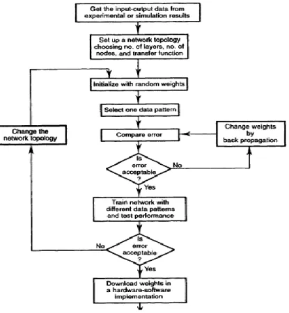
Figure 1 the flowchart for training a neural network is given below:
The general methodology for designing a neural network can be summarized as follows: 1. Select feedforward network, if possible.
2. Select input nodes equal to the number of input signals and output nodes equal to the number of output signals.
3. Select appropriate input scale factors for normalization of input signals and output scale factors for denormalization of output signals.
4. Create input-output training data table. Capture the data from an experimental plant. If a model is available, make a simulation and generate data from the simulation result.
5. Select a development system.
6. Set up a network topology in the development system. Assume that it is a three-layer network. Select hidden layer nodes average of input and output layer nodes. Select transfer function. The training procedure is highly automated in the development system. The steps are given below.
7. Select an acceptable network training error E. Initialize the network with random positive and negative weights.
8. Select an input-output data pattern from the training data file. Change weights of the network by back propagation training principle.
9. After the acceptable error is reached, select another pattern and repeat the procedure. Complete training for all the patterns.
10. If a network does not converge to acceptable error, increase the hidden layer neurons or increase number of hidden layers (most problems can be solved by three layers), as necessary. A too high number of hidden layer neurons or number of hidden layers will increase the training time, and the network will tend to have memorizing property.
11. After successful training of the network, test the network performance with some intermediate data input. The weights are then ready for downloading.
12. Select appropriate hardware or software for implementation. Download the weights.
3. DESIGN OF PROPOSED NNC
The Neural Network seems to have maximum impact on power electronics area that is evident by the publications in the literature [6-10]. NNC is easier to design, simpler, and gives better performance compared to other controllers. The neurons are highly interconnected and are connected by weighted links. The weighted links carry the signal. Each neuron has a single threshold value. The weighted sum of the input in formed and then subtracted from the threshold value to get the activation signal of the neuron.
The activation signal is passed through an activation function to produce the output signal.
This application is built using the Matlab toolbox, where the NN structure is easy to construct using gensim(net) instruction in the mfile, and the system construction and simulation becomes easy by using Simulink.
The network has three layers: 1. Input layer
2. Hidden layer 3. Output layer.
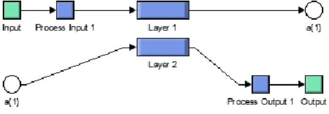
The hidden layer functions to associate the input and output layers. The input and output layers (defined as buffers) have neurons equal to the respective number of signals. The input layer neurons do not have transfer function, but there is scale factor in each input to normalize the input signals. The input layer transmits the computed signals to the hidden layer, which in turn, transmits to the output layer, as shown. The hidden layer passes calculated weights to the output layer. The error is presented to input layer through back propagation (feedback) when actual output is different from the desired level. Hence the weights are adjusted to minimize the error through training and learning of the neural network. The process continues until the output is acceptable or pre-configured learning time is achieved. Currently, the back propagation network is most popular. There are many algorithms to determine parameters (weight and bias) in neural network system. Among these algorithms, LM algorithm is used which is the fastest for NN training. It is over four times faster than others. This network works with supervised learning where data set is presented to train the network before simulation is run to get output results. Shown in Figure 2 and Figure 3.
Figure 3. Custom Neural Network (Proposed Neural Network)
Network input and output signals may be logical (0, 1), discrete bidirectional (± 1) or continuous variables. The transfer function is sigmoid function which possesses continuous and nonlinear properties. It is represented by the following equation:
The sigmoid functions at output can be clamped to convert to logical variables. ANN control learns from experience as Artificial Neural Networks are trained through data set in supervised learning. The analysis is done in terms of Mean Square Error (MSE) representing the difference between desired and actual output levels. In ideal conditions, the MSE approaches to zero.
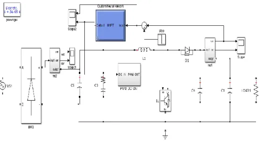
The proposed NNC is simulated and its performance is evaluated by using it as a controller in DC-DC (buck/boost) and AC-DC-DC converter circuits as shown in Figure 4 and Figure 5. To obtain high performance control of a system, a good model of the system is needed. It is desirable that the conversion be made with low losses in the converter. To obtain low losses, resistors are avoided in the power electronics converter circuits. Capacitors and inductors are used instead since ideally they have no losses. The electrical components can be combined and connected to each other in different ways, called different converter (DC-DC,
Figure 4. Neural Network Controller for DC-DC (Buck) Power Converter Circuit
AC-DC) topologies, each one having different properties. By using pulse-width modulation (PWM) control, regulation of output voltage is achieved by varying the duty cycle of the switch. Duty cycle refers to ratio of the period where power semiconductor is kept ON to the cycle period.
The proposed converter circuit uses IGBT as the switching device. Use of IGBTs allow to build cheaper and better converters. They have three attractive advantages: higher switching frequency, easy and simple gate control and no need for snubber circuits. IGBTs are continuously controllable during turn on and turn off. This makes overcurrent limitation much easier and allows dV/dt control to reduce the and dV/dt stresses. As shown in Figure 6.
Figure 5. Neural Network Controller for DC-DC (Boost) Power Converter Circuit
Figure 6. Neural Network Controller for AC-DC Power Converter Circuit
4. SIMULATION RESULTS
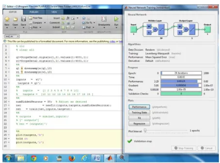
The proposed Neural Network Controller is designed and simulated using SIMULINK toolbox of MATLAB [11] and the performance of the system is evaluated. The output of the NNC is generates the required PWM signal which controls the switching action of the semiconductor switch IGBT so as to produce the required output voltage. Figures 7 and Figure 8 show the simulation results as below.
Figure 7. Training of Proposed NNC
Figure 8. Output of DC-DC (buck) Converter using Proposed NNC
5. CONCLUSION
The simulation results show that the proposed Neural Network Controller has a better performance compared to the conventional PID controller. The proposed controller can be applied to any switched power electronics circuits such as DC-DC (Buck/Boost) or AC-DC cirucits.
REFERENCES
[1] Mohan, Undeland and Robbins, "Power Electronics: Converters, Applications and Design", Wiley, 1989.
[2] B.K.Bose,"Expert system, fuzzy logic and neural network applications in power electronics and motion control," Proc. IEEE, vol. 82, no. 8, pp. 1303-1323, 1994.
[3] L.A.Zadeh, "Outline of a new approach to the analysis of systems and decision processes", IEEE Trans. Syst., Man, Cybern., vol. SMC-3, no.1, pp. 28-44, 1973.
[4] B.K.Bose, "Neural Network Applications in Power Electronics and Motor Drives-An Introduction and Perspective", IEEE Trans. on Industrial Electronics, vol.54, no.1, pp. 14-33, 2007.
[5] A.K.Jain, J.Mao, K.M.Mohiuddin, "Artificial Neural Networks: A Tutorial", IEEE Proc., pp.31-44, 1996.
[6] Bambang Sujanarko, Mochamad Ashari, Mauridhi Hery Purnomo, "Neural Network Controller for Asymmetric Cascaded Multilevel Inverter", International Journal of Computer Applications, vol. 11, no. 6, pp. 17-22, 2010.
[7] W.M.Utomo, Z.A.Haron, A.A.Bakar, M.Z.Ahmad, Taufik, "Voltage Tracking of a DC-DC Buck-Boost Converter Using Neural Network Control", International Journal of Computer Technology and Electronics Engineering (IJCTEE), vol.1 no. 3, pp.108-113, 2011.
[8] Venugopal Chitra, K.S.Ravichandran, R.Varadrajan, "Artificial Neural Network in Field Oriented Control for Matrix Converter Drive", World Applied Sciences Journal, vol. 16, no. 4, pp. 560-567, 2012.
[9] T.V.Mumcu, K. Gulez, M.Mercimek, "Switching Control of an AC/DC Converter by Neural Networks", International Journal of Information Technology, vol.11, no.5, pp. 78-85.
[10] Min-Huei Kim, M. Godoy Simoes, B.K.Bose, "Neural Network-Based Estimation of Power Electronic Waveforms", IEEE Trans. on Power Electronics, vol.11, no.2, pp. 383-389, 1996.
[11] Hemant Mehar, "MATLAB Simulation Techniques in Power Electronics", IEEE Technology and Engineering Education, vol. 7, no. 4, pp. 62-65, 2012
BIOGRAPHIES OF AUTHORS
Ms. K.J.Rathi is a Assistant Professor in Electronics and Telecommunication Department of Prof Ram Meghe College of Engineering & Management, Badnera-Amravati. She completed her B.E.(Industrial Electronics) and M.E.(Electronics) from Dr. B.A.M.U, Aurangabad in 1999 and 2009 respectively. Her research interests are Power Electronics Systems, Artificial Intelligence and VLSI Design.
Dr. M. S. Ali is a Professor and Principal of Prof RamMeghe College of Engineering & Management, Badnera – Amravati. He obtained his B.E. (Electronics& Power) and M.Tech. (Power Electronics) from Nagpur University and I.I.T. Powai, Mumbai in 1981& 1984 respectively He obtained his Ph.D. from SGB Amravati University in 2006. He has been on the SGB University’s various bodies like Board of Studies, Faculty of Engineering &Technology and Academic Council since last fifteen years. He is Hon’ble Chancellors nominee on the senate of RTM Nagpur University. His research interests are Operating Systems, Artificial Intelligence and Java Technologies.