Abstract— Flexible AC Transmission Systems (FACTS) controllers have been used in power systems since the 1970s with the objective of improving system dynamic performance. Due to the environmental, right-of-way, and cost problems in both bundled and unbundled power systems, many transmission lines have been forced to operate at almost their full capacities worldwide. FACTS controllers enhance the static performance viz. increased loading, congestion management, reduced system loss, economic operation, etc., and dynamic performance viz. increased stability limits, damping of power system oscillation, etc. In this paper, an overview of FACTS controllers is explained. Various FACTS controller several devices in FACTS family are also discussed.The thesis explains various power quality problems and the FACTS controllers that are used to mitigate the power quality problems. Proposed FACTS controller for a particular type of problem is also given. The simulation results give the clear observation of how the FACTS devices improve the power quality. The simulation work is done on Static Var Compensator (SVC) and Static Synchronous Series Compensator(SSSC).
Index Terms—FACTS, Matlab/Simulink, Real and reactive power, SSSC and SVC
I. INTRODUCTION
The quality of power should be maintained. To improve the power quality various power quality problems are needed to discuss. Next chapter provides details of the power quality problems that occur in power system [1, 2]. The AC transmission system has various limits classifieds static limits and dynamic limits. These inherent power system limits restrict the power transaction, which lead to the under utilization of the existing transmission resources. Traditionally, fixed or mechanically switched shunt and series capacitors, reactors and synchronous generators were being used to solve much of the problem. However, there are restrictions as to the use of these conventional devices. Desired performance was not being able to achieve effectively. Wear and tear in the mechanical components and slow response were the heart of the problems. There was greater need for the alternative technology made of solid state devices with fast response characteristics. The need was further fuelled by worldwide restructuring of electric utilities, increasing environmental and efficiency regulations and difficulty in getting permit and right of way for the construction of overhead transmission lines. This, together with the invention of Thyristor switch (semiconductor device), opened the door for the development of power electronics devices known as Flexible AC Transmission Systems (FACTS) controllers. The path from historical
Thyristor based FACTS controllers to modern state-of-the-art voltage source converters based FACTS controllers, was made possible due to rapid advances in high power semiconductors devices. FACTS controllers have been in use in utilities around the world since 1970s, when the first utility demonstration of first family of FACTS named as Static Var Compensator (SVC) was accomplished. Since then the large effort was put in research and development of FACTS controllers. Static Synchronous Compensator (STATCOM), Static Synchronous Series Compensator (SSSC) and Unified Power Flow Controller (UPFC) etc., bus voltages, line impedances and phase angles in the power system can be regulated rapidly and flexibly. These FACTS controllers are based on voltage source converters. Thus, FACTS can facilitate the power flow control, enhance the power transfer capability, decrease the generation cost, and improve the security and stability of the power system. A Static Synchronous Series Compensator (SSSC) is a member of FACTS family which is connected in series with a power system. It consists of a solid state voltage source converter which generates a controllable alternating current voltage at fundamental frequency. When the injected voltage is kept in quadrature with the line current, it can emulate as inductive or capacitive reactance so as to influence the power flow through the transmission line. While the primary purpose of a SSSC is to control power flow in steady state, it can also improve transient stability of a power system.
II. POWERQUALITYPROBLEMS
Power quality problems have increasingly become a substantial concern over the last decade, but surprisingly few analytical techniques have been developed to overcome these disturbances in system-equipment interactions. Power-quality problems arise when system incompatibility occurs between the AC power and the equipment. Either the quality of the AC distribution system or the AC voltage can contribute to power quality problems. In each case, the solution is different. So, in order to find the right solution or solutions, it is important to diagnose the problems correctly. Various power quality problems are:
2.1. TEMPORARY PHENOMENA 2.1.1. Transients
2.1.2 Long duration voltage variations 2.1.3. Sustained interruption
2.1.4. Short duration voltage variations
2.2. STEADY STATE PHENOMENA 2.2.1 Voltage unbalance
2.2.2 Waveform distortion
Performance and analysis of FACTS controller
SVC and SSSC using MATLAB/Simulink
2.3. VOLTAGE FLUCTUATION AND FLICKER 2.4. POWER FREQUENCY VARIATIONS
III. FLEXIBLEACTRANSMISSIONSYSTEMS The power industry term FACTS (Flexible AC Transmission Systems) covers a number of technologies that enhance the security, capacity and flexibility of power transmission systems. FACTS solutions enable power grid owners to increase existing transmission network capacity while maintaining or improving the operating margins necessary for grid stability. As a result, more power can reach consumers with a minimum impact on the environment, after substantially shorter project implementation times, and at lower investment costs - all compared to the alternative of building new transmission lines or power generation facilities.FACTS is defined by the IEEE as “a power electronic based system and other static equipment that provide control of one or more AC transmission system parameters to enhance controllability and increase power transfer capability.”Flexible AC Transmission Systems, called FACTS, got in the recent years a well-known term for higher controllability in power systems by means of power electronic devices. Several FACTS-devices have been introduced for various applications worldwide. A number of new types of devices are in the stage of being introduced in practice. Even more concepts of configurations of FACTS-devices are discussed in research and literature.
The basic applications of FACTS-devices are: 1. Power flow control,
2. Increase of transmission capability, 3. Voltage control,
4. Reactive power compensation, 5. Stability improvement, 6. Power quality improvement, 7. Power conditioning, 8. Flicker mitigation,
In all applications the practical requirements, needs and benefits have to be considered carefully to justify the investment into a complex new device. Fig.1 shows the basic idea of FACTS for transmission systems. The usage of lines for active power transmission should be ideally up to the thermal limits. Voltage and stability limits shall be shifted with the means of the several different FACTS devices. It can be seen that with growing line length, the opportunity for FACTS devices gets more and more important.
The influence of FACTS-devices is achieved through switched or controlled shunt compensation, series compensation or phase shift control. The devices work electrically as fast current, voltage or impedance controllers. The power electronic allows very short reaction times down to far below one second. In the following a structured overview on FACTS-devices is given. These devices are mapped to their different fields of applications. Detailed introductions in FACTS-devices can also be found in the literature with the main focus on basic technology, modeling and control.
Fig. 1.Operational limits of transmission lines for different voltage levels[5]
IV. SVC
Electrical loads both generate and absorb reactive power. Since the transmitted load varies considerably from one hour to another, the reactive power balance in a grid varies as well. The result can be unacceptable voltage amplitude variations or even a voltage depression, at the extreme a voltage collapse. A rapidly operating Static Var Compensator (SVC) can continuously provide the reactive power required to control dynamic voltage oscillations under various system conditions and thereby improve the power system transmission and distribution stability. Installing an SVC at one or more suitable points in the network can increase transfer capability and reduce losses while maintaining a smooth voltage profile under different network conditions. In addition an SVC can mitigate active power oscillations through voltage amplitude modulation. SVC installations consist of a number of building blocks. The most important is the Thyristor valve, i.e. stack assemblies of series connected anti-parallel Thyristors to provide controllability.
Fig.2SVC building blocks and voltage / current characteristic[5]
arc furnace. On transmission level the first SVC was used in 1979. Since then it is widely used and the most accepted FACTS-device.
V. SSSC
While the TCSC can be modeled as a series impedance, the SSSC is a series voltage source. The principle configuration is shown in Figure 3, which looks basically the same as the STATCOM. But in reality this device is more complicated because of the platform mounting and the protection. A Thyristor protection is absolutely necessary, because of the low overload capacity of the semiconductors, especially when IGBTs are used. The voltage source converter plus the Thyristor protection makes the device much more costly, while the better performance cannot be used on transmissionlevel. The picture is quite different if we look into power quality applications. This device is then called Dynamic Voltage Restorer (DVR). The DVR is used to keep the voltage level constant, for example in a factory infeed. Voltage dips and flicker can be mitigated. The duration of the action is limited by the energy stored in the DC capacitor. With a charging mechanism or battery on the DC side, the device could work as an uninterruptible power supply.
Fig.3Principle setup of SSSC
VI. MATLABMODELS &RESULTS AND COMPARISON 1. MATLAB Model of StaticVar Compensator
(SVC)
Static Var Compensator (SVC) is used to regulate voltage on a 500 kV, (3000 MVA & 2500MVA system). When system voltage is low the SVC generates reactive power (SVC capacitive). The SVC is rated +200 Mvar capacitive and 100 Mvar inductive. The Static Var Compensator block is aaphasor model representing the SVC static and dynamic characteristics at the system fundamental frequency. The SVC is set in voltage regulation mode with a reference voltage Vref=1.0 pu. The voltage droop is 0.03 pu/ 200MVA. A good approximation of the maximum frequency range represented by the PI line model is given by the following equation:
f
max
Nv
/
8
l
where
N Number of PI sections
v
Propagation speed in km/s =
LC
1
L in H/km, C in F/km
l Line length in km
For example, for a 100 km aerial line having a propagation speed of 300,000 km/s, the maximum frequency range represented with a single PI section is approximately 375 Hz. For studying interactions between a power system and a control system, this simple model could be sufficient. However for switching surge studies involving high-frequency transients in the kHz range, much shorter PI sections should be used. In fact, you can obtain the most accurate results by using a distributed parameters line model. Frequency used for RLC specifications
Frequency f, in hertz (Hz), used to compute the complex impedance of the line:
[1]
2
f
[2]Z
R
j
L
[3]y
j
C
[4]
Z
c
z
/
y
[5]
gamma
zy
whereR is the resistance per unit length, L is the inductance per unit length, and C the capacitance per unit length of the line.
Resistance per unit length
The resistance per unit length of the line, in ohms/km (Ω/km).
Inductance per unit length
The inductance per unit length of the line, in henries/km (H/km). This parameter can not be zero, because it would result in an invalid propagation speed computation.
Capacitance per unit length
The capacitance per unit length of the line, in farads/km (F/km). This parameter can not be zero, because it would result in an invalid propagation speed computation.
Length
The line length in km.
VII. EDITORIAL POLICY
VIII. PUBLICATION PRINCIPLES
and critical reviews of classical subjects and topics of The
2.MATLAB model of Static Synchronous Series
Compensator (SSSC),
The Static Synchronous Series Compensator (SSSC), one of the key FACTS devices, consists of a voltage-sourced converter and a transformer connected in series with a transmission line. The SSSC injects a voltage of variable magnitude in quadrature with the line current, thereby emulating an inductive or capacitive reactance. This emulated variable reactance in series with the line can then influence the transmitted electric power. In our demo, the SSSC is usedto damp power oscillation on a power grid following a three-phase fault. The power grid consists of two power generation substations and one major load center at bus B3. The first power generation substation (M1) has a rating of 3000 MVA, and second 2500 MVA.
IX. CONCLUSION A conclusion section is not requi
Fig 5 MATLAB Simulink Model of SSSC System
6.3 Simulation Results
In this thesis we discuss SVC, STATCOM and SSSC based MATLAB molding Results
Fig.6 Voltage profile without fault SVC System
Fig.7 Power profile without fault SVC System
Fig.8 Voltage profile with fault SVC System
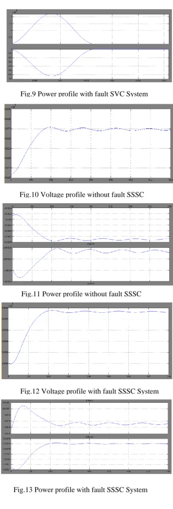
Fig.9 Power profile with fault SVC System
Fig.10 Voltage profile without fault SSSC System
Fig.11 Power profile without fault SSSC System
Fig.12 Voltage profile with fault SSSC System
7.5 Comparison
Issue SVC SSSC
V/I characteristic Good overvoltage performance Impedance
Good under voltage performance Voltage source
Control range freely adjustable to any rangeby TCR/TSR /TSC branches
Symmetrical
Modularity TCR/TSR/TSC branches used in SVC and TCSC/TPSC
Redundancy
Degraded mode operation
Same converter usable for various applications
UPFC, SSSC
configurations are used in the CSC
Response time 2 to 3 cycle 3 to 4 cycle Transient
behavior
Available before, during and after critical system conditions
Self protecting at critical system faults
Space requirements
100 % 60 to 70 %
Availability > 99 % 90 to 92 %
Investment costs 100 % 130 %
VII.CONCLUSIONS
The thesis explains various power quality problems and the FACTS controllers that are used to mitigate the power quality problems. The standard FACTS controller for a particular type of problem is also given. The simulation results give the clear observation of how the FACTS devices improve the power quality. The simulation work is done on Static Var Compensator (SVC)andStatic Synchronous Series Compensator(SSSC).SVC and SSSC are providing better power quality under variation of source voltage and when the system is suddenly loaded. The thesis includes the simulation results of the SVC and SSSC only. The future work given as the simulation results of the systems for various power quality problems with all remaining FACTS devices. Then it can be very easy to find an exact FACTS device for a particular type of power quality problem
REFERENCES
[1].Baseri, M.A.A. Nezhad, M.N. ; Sandidzadeh, M.A. “Compensating procedures for power quality amplification of AC electrified railway systems using FACTS” PP.No. 518 - 521 Power Electronics, Drive Systems and Technologies Conference (PEDSTC), 2011
[2]. Mahdad, B. Contribution to the improvement of power quality using multi hybrid model based wind-shunt FACTSPage(s): 1 - 5 Environment and Electrical Engineering (EEEIC), 2011 10th International Conference.
[3]. Suja, K.R. Raglend, I.J. Power quality improvement in grid connected wind energy system using STATCOM Page(s): 259 - 266 computing, Electronics and Electrical Technologies (ICCEET), 2012 International Conference.
[4].Yuma, G.P. Kusakana, K. Damping of oscillations of the IEEE 14 bus power system by SVC with STATCOM Page(s): 502 - 507 Environment and Electrical Engineering (EEEIC), 2012 11th International Conference .
[5].Singh, R. Singh, D.K. Simulation of D-STATCOM for Voltage Fluctuation Page(s): 225 - 230 Advanced Computing & Communication Technologies (ACCT), 2012 Second International Conference
[6].Chopade, P. Bikdash, M. ; Kateeb, I. ; Kelkar, A.D. Reactive power management and voltage control of large Transmission System using SVC (Static VAR Compensator) Page(s): 85 - 90 Southeastcon, 2011 Proceedings of IEEE
[7]. Gelen, A. Yalcinoz, T. The behaviour of TSR-based SVC and TCR-based SVC installed in an infinite bus system Page(s): 120 - 124 Electrical and Electronics Engineers in Israel, 2008. [8]. C.hivite-Zabalza, J. Rodriguez, M. ; Asensio, J. ; Atutxa,
I. Power quality analysis of a Synchronous Static Series Compensator (SSSC) connected to a high voltage transmission networkPage(s): 1 - 8 Power and Energy Society General Meeting, 2010 IEEE
[9].Wei Qiao Venayagamoorthy, G.K. ; Harley, R.G. Missing-Sensor-Fault-Tolerant Control for SSSC FACTS Device With Real-Time Implementation Volume: 24 , Issue: 2 Page(s): 740 - 750 Power Delivery, IEEE Transactions onApril 2009
[10]. IEEE Power Engineering Review on “Trends in Power Quality Monitoring”, by Mark McGranaghan, August-2001, page no.1-9. [11]. A text book on “Power Quality Enhancement Using Custom Power Devices”, by A. Ghosh and G. Ledwich, Norwell, MA: Kluwer, 2002, page no. 293.
[12]. A text book on “FACTS Controllers in Power Transmission and Distribution” by K.R. Padiyar from new age international publ.2007 page no384-394
![Fig. 1.Operational limits of transmission lines for different voltage levels[5]](https://thumb-us.123doks.com/thumbv2/123dok_us/8097514.2145864/2.893.488.774.133.264/fig-operational-limits-transmission-lines-different-voltage-levels.webp)