Published online January 17, 2015 (http://www.sciencepublishinggroup.com/j/jeee) doi: 10.11648/j.jeee.s.2015030201.17
ISSN: 2329-1613 (Print); ISSN: 2329-1605 (Online)
Design of a PID feed-forward controller for controlling
Output fluid temperature in shell and tube hear exchanger
Navid Khalili Dizaji
1, *, Aidin Sakhvati
2, Seyed Hossein Hosseini
31
Department of Mechatronics Engineering, Tabriz Branch, Islamic Azad University, Tabriz, Iran
2
Department of Electrical Engineering, Tabriz Branch, Islamic Azad University, Tabriz, Iran
3
Department of Electrical & Computer Engineering, University of Tabriz, Tabriz, Iran
Email address:
[email protected] (Navid K. D.), [email protected] (Aidin S.), [email protected] (Seyed H. H.)
To cite this article:
Navid Khalili Dizaji, Aidin Sakhvati, Seyed Hossein Hosseini. Design of a PID Feed-Forward Controller for Controlling Output Fluid Temperature in Shell and Tube Hear Exchanger. Journal of Electrical and Electronic Engineering. Special Issue: Research and Practices in Electrical and Electronic Engineering in Developing Countries. Vol. 3, No. 2-1, 2015, pp. 30-34. doi: 10.11648/j.jeee.s.2015030201.17
Abstract: The most important part in chemical processes, which is directly related to energy consumption, is heat exchanger.
Main purpose of heat exchanger is transferring heat from hot fluid to cold fluid. There are different heat exchangers in industry, which their common types are shell and tube heat exchangers. In these heat exchangers, one fluid flows in tubes and the other in shell around tubes. In heat exchangers, one of the important issues is reaching output fluid temperature to given temperature in the least possible time. In this paper, PID controller along with forward-feeding controller was designed to control output fluid temperature of a shell and tube heat exchanger. First, process mathematical modeling is done using experimental data, and then the controller is designed. Designed controller regulates output temperature of heating fluid to a desired point in the least possible time without considering a non-linear process. Then, controller performance is evaluated by unit step response analysis and performance indicators related to the control system. Modeling all processes and designing controllers are done in MATLAB software Simulink.Keywords: PID Controller, Feed-Forward Controller, Shell and Tube Heat Exchangers
1. Introduction
In a chemical process, heat exchangers are used in order to transfer heat from one hot fluid through the solid wall to a cold fluid. There are various types of heat exchangers in industry. Certain type of these heat exchangers, which are known as shell and tube heat exchangers have been produced in different configurations as well as various sizes and can operate in high pressure. These heat exchangers apply in fields such as condensation, electricity production, chemical processes, medicine, etc. one shell and tube heat exchanger is a set of parallel tubes, which are enclosed in a cylindrical cover. In heat exchangers, one fluid flows in tubes and other fluid around tubes [1].
Researches about controlling heat exchangers have dealt with other heat exchangers like plate exchangers and control plans like neural network, and fuzzy network in order to control output fluid temperature of these heat exchangers. Therefore, there is less attention to controlling these heat exchangers' temperature. It is necessary to mention that
regarding domestic research, there is no valid plan in order to control temperature of these heat exchangers and this work in unique in this regard.
This paper deals with a shell and tube heat exchanger and one-input-output system using experimental data. Output fluid temperature of heat exchanger should be kept in an optimized point regarding process need. Then a PID controller runs with feed-forward controller in order to reach control purpose. Also analyzing designed controller performance is done in the time domain. In order to evaluate designed controller performance, unit step response analysis and performance indicators were used. Processes modeling and controllers' design indicators steps have implemented in MATLAB software Simulink.
2. Mathematical Modeling
flows through tubes in heat exchanger; while process fluid flows through inter-shell and tubes. After heating fluid was done by super hot vapor, dense vapor exits system in 930c. Heat exchanger warms fluid to 520c in fact, the purpose is controlling output fluid temperature that enters heat exchanger.
Figure (1) shows schematic of one shell and tube heat exchanger.
There are different assumptions for shell and tube heat exchanger. First assumption is that rate of input and output fluid stream is identical. Second assumption is that heat storage capacity of walls is trivial. Shell walls are fully
insulated.
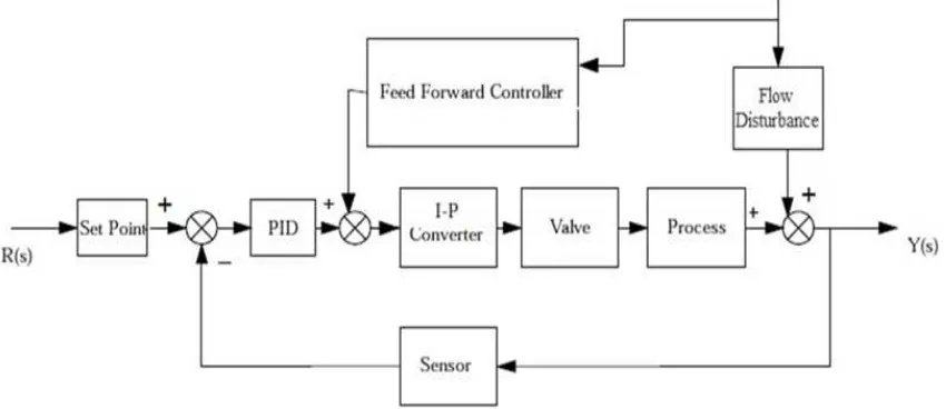
Figure (2) shows PID control system with feedback controller for shell and tube heat exchanger.
Fig (1). shell and tube heat exchanger
Fig (2). Shell and tube heat exchanger control system
In figure (2) used, control valve is opening with air. Used sensor in this design is a thermocouple with a transmitter. Thermocouple is used to measure temperature in control architecture feedback path. Output fluid temperature is measured by the thermocouple, and its output is sent to the transmitter. Finally, temperature output is converted to a standard signal in 14-20 mA range. This transmitter unit output is given to the PID controller unit. There is an orifice in this sheet, which creates pressure difference. In fact, it reduces pressure and this pressure difference can be converted to standard signal 4-20 mA using a transmitter. In this control system, controller estimates error feed-forward and changes the control variable before distortion can influence output.
Controllers run control algorithm and send a combined signal in order to control output temperature of shell and tube heat exchanger to drive. Then command for final control is
given from drive. Drive unit is current to pressure pneumatic heat exchanger, and it is the ultimate control unit for pneumatic valve. Drive converts controllers combined output signal to one standard pressure unit in the 3-15psig range. Drive decides to open and close valve considering sent signals. As a result, vapor stream enters heat exchanger and develops final output temperature using other inputs. Generally, there are two distortions in this process, one is changes in the input fluid stream, and the other is changes in input fluid temperature. However, in practice, changes in input fluid stream create significant distortion than temperature changes.
Fig (3). diagram block PID controller with feed-forward controller for shell-tube heat exchanger
Fig (3): diagram block PID controller with feed-forward controller for shell-tube heat exchanger.
Controller imposes control using the final control elements through the drive. Sensor receives output and feedbacks it to the controller. In fact, temperature is measured by sensor and output signal is sent to the controller, where it is compared
with the optimal point. Output signal of the controller enters the flow to pressure pneumatic exchanger that creates a pneumatic signal to regulate control valve and vapor stream enters. This stream enters heat exchanger and creates final output temperature with other inputs.
Experimental data for process are presented in table (1) [3]: Table (1). experimental data for heat exchanger control process
500C/(kg/sec) Exchanger response to vapor
1.6kg/sec Control valve capacity
30 sec Process time constant
3sec Control valve time constant
4-0 mA Drive current range
50-1500C Sensor temperature
3-15psig Drive pressure range
10 sec Sensor time constant
Transformation functions related to different system elements and process, and their rates are gathered in table (2).
Table (2). transformation function and rates of different system components
30s+1 Process transformation function
3s+1 Valve function
0.75 Drive rate
30s+1 Distortion function
10s+1 Sensor function
In this control plan, feed-forward controller regulates distortion by the input fluid stream. Feed-forward transformation function is shown by Gcf(s), which is expressed as equation (1) [4]:
( )
( )
( )
s G
s G s G
p d
cf =− (1)
In equation (1), Gp(S) is process transformation function and Gd(s) is distortion transformation function for input
stream, which are shown by equations (2) and (3), respectively.
( )
1 33 90
5
2+ +
= −
s s
e s
G
s
p (2)
( )
1 30
1 + =
s s
Gd (3)
By substituting current distortion transformation function and process transformation function in equation (1), feed-forward controlling function is expressed as equation (4):
( )
1 9 30 27
2 0 6 6 18
2 2
+ +
− − − =
s . s
. s . s s
Gcf (4)
Fig (4). transformation functions and rates in sell and tube heat exchanger control system
In order to regulate PID controlling parameters Ziegler–Nichols closed loop regulation method was used, which is an automatic regulation method. In this method, Ku is the final rate. High increase in this rate pushes the system to instability. In this method, system fluctuates and frequency (w) and vibration period (Pu) are calculated from fluctuations. Table (3) shows regulation laws based on Ziegler–Nichols closed loop fluctuation [5].
Table (3). PID parameters' regulation law
method
d τ i
τ c
K
Ziegler–Nichols
u
P 0/125 u
P 0 /5 u
K 0 /6
3. Results of Computer Simulation
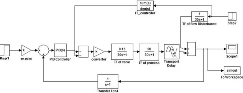
Using experimental data, PID controller Simulink with feed-forward controller for shell and tube heat exchanger is shown in figure (5):
Fig (5). PID controlling Simulink with feed-forward controller for shell and tube heat exchanger
For PID controller, the amount of Kc ,τd τiparameters are obtained by Ziegler–Nichols closed loop regulation method, which is shown in table (4).
Table (4). PID parameters regulation
method
d τ i
τ c
K
Ziegler–Nichols
59 / 3 395
/ 14 28
/ 14
Purpose of designing control systems in time range is using
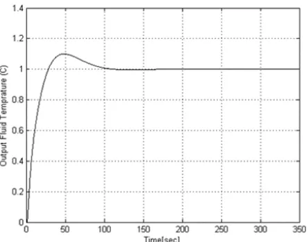
features and characteristics of system time domain. These characteristics are often expressed as standard values in ascending time, settlement time, maximum jump, peak time, and stable mood error by unit step response. In this designed controller, settlement time and maximum mutation were evaluated using unit step response analysis.
Fig (6). Unit step response PIN controller with feed-forward controller in shell and tube heat exchanger
Maximum mutation is the between time response's Peal and sustainable output. This relation can be defined as equation (5) [6]:
( )
( )
( )
* %C C t C M
% P p ∞ 100
∞ −
= (5)
Settlement time (ts) is required time for system to reach and stays final value range (about 2%-5% of final value) [6]. In this article, it is considered as 5% of final value.
By analyzing a unit step response of this control system settlement time is 90. 23 seconds, and maximum mutations are 9.1.
Performance indicators were used in order to evaluate controller performance. Performance indicators for evaluating this control system are integral absolute error (IAE), integral square error (ISE), integral time absolute error (ITAE) and integral time square error (ITSE). Performance indicator is a quantitative amount of system performance. A system is considered optimal control system when its performance indicator reaches to the minimum. Performance indicators can be obtained by following relations [6]:
( )
∫
∞
=
0
dt t e
IAE (6)
( )
∫
∞
=
0 2tdt
e
ISE (7)
( )
∫
∞
=
0
dt t e t
ITAE (8)
( )
∫
∞
=
0 2
dt t te
ITSE (9)
Performance indicators for PID controller with feed-forward controller for shell and tube heat exchanger are shown in table (5):
Table (5). PID controller performance indicators with feed-forward controller
ITSE ITAE
ISE IAE
controller
474 / 3 66 / 80 331
/ 0 528 / 3
PID controller with feed-forward
4. Discussion and Conclusion
In this paper, we designed a PID feed-forward controller for controlling output fluid temperature in shell and tube heat exchanger. Maximum mutation in this control system was 9.1% and settlement time is 90. 23 seconds, which in chemical process's settlement time about few minutes are ideal. Performance indicator's values for this system are in a satisfactory range. Regarding obtained results, we can control output fluid temperature in shell and tube heat exchanger in the least possible time without considering non-linearity of the process. By controlling output fluid temperature in shell and tube heat exchanger; we can have significant savings in energy consumption. For future research, other control systems like fuzzy controller, internal model and neural networks can be used.
References
[1] Ramesh, K., Dusan, R., Fundamentals of heat exchanger design, John Willey and Sons, New York, 2003.
[2] Kaddour, N., Process modeling, and control in chemical engineering, Marcel Dekker Inc, New York, 1989.
[3] Gopal, M., Control systems principles and design, Tata McGraw-Hill Education, New York, 2008.
[4] Shue L., Feng, L., "Feed forward Compensation Based the Study of PID Controller", Advances in Intelligent and Soft Computing, Vol. 149, pp. 59-64, 2012.
[5] Kiam, A., Gregory C., Yun, L., "PID control system analysis, design and technology", Control System Technology, Vol. 13, pp. 559-576, 2005.