Materials Science and Engineering Publications
Materials Science and Engineering
2013
Coil optimization for electromagnetic levitation
using a genetic like algorithm
Zachary L. Royer
Iowa State University, [email protected]
Carl Tackes
Iowa State University, [email protected]
Richard A. LeSar
Iowa State UniversityRalph E. Napolitano
Iowa State University, [email protected]
Follow this and additional works at:
http://lib.dr.iastate.edu/mse_pubs
Part of the
Electromagnetics and Photonics Commons
, and the
Metallurgy Commons
The complete bibliographic information for this item can be found at
http://lib.dr.iastate.edu/
mse_pubs/117
. For information on how to cite this item, please visit
http://lib.dr.iastate.edu/
howtocite.html
.
Coil optimization for electromagnetic levitation using a genetic like
algorithm
Abstract
he technique of electromagnetic levitation (EML) provides a means for thermally processing an electrically conductive specimen in a containerless manner. For the investigation of metallicliquids and related melting or freezing transformations, the elimination of substrate-induced nucleation affords access to much higher undercooling than otherwise attainable. With heating and levitation both arising from the currents induced by the coil, the performance of any EML system depends on controlling the balance between lifting forces and heating effects, as influenced by the levitation coil geometry. In this work, a genetic algorithm is developed and utilized to optimize the design of electromagnetic levitation coils. The optimization is targeted specifically to reduce the steady-state temperature of the stably levitated metallic specimen. Reductions in temperature of nominally 70 K relative to that obtained with the initial design are achieved through coil optimization, and the results are compared with experiments foraluminum. Additionally, the optimization method is shown to be robust, generating a small range of converged results from a variety of initial starting conditions. While our optimizationcriterion was set to achieve the lowest possible sample temperature, the method is general and can be used to optimize for other criteria as well.
Keywords
Ames Laboratory
Disciplines
Electromagnetics and Photonics | Materials Science and Engineering | Metallurgy
Comments
The following article appeared inJournal of Applied Physics113 (2013): 214901 and may be found at http://dx.doi.org/10.1063/1.4807788.
Rights
Copyright 2013 American Institute of Physics. This article may be downloaded for personal use only. Any other use requires prior permission of the author and the American Institute of Physics.
Coil optimization for electromagnetic levitation using a genetic like algorithm
Z. L. Royer, C. Tackes, R. LeSar, and R. E. NapolitanoCitation: Journal of Applied Physics 113, 214901 (2013); doi: 10.1063/1.4807788
View online: http://dx.doi.org/10.1063/1.4807788
View Table of Contents: http://scitation.aip.org/content/aip/journal/jap/113/21?ver=pdfcov Published by the AIP Publishing
Articles you may be interested in
OPTIMIZATION OF LONG RURAL FEEDERS USING A GENETIC ALGORITHM AIP Conf. Proc. 1239, 31 (2010); 10.1063/1.3459766
Instrument design and optimization using genetic algorithms Rev. Sci. Instrum. 77, 105107 (2006); 10.1063/1.2360987
Optimal Topology Design of Products Using Genetic Algorithm AIP Conf. Proc. 712, 2137 (2004); 10.1063/1.1766851
Optimization and implementation of piezoelectric radiators using the genetic algorithm J. Acoust. Soc. Am. 113, 3197 (2003); 10.1121/1.1568944
Coil optimization for electromagnetic levitation using a genetic like algorithm
Z. L. Royer,1,2C. Tackes,1,2R. LeSar,1,2and R. E. Napolitano1,2,a)
1
Material Science and Engineering, Ames Laboratory, US DOE, Ames, Iowa 50011, USA
2
Department of Material Science and Engineering, Iowa State University, Ames, Iowa 50011, USA
(Received 29 January 2013; accepted 2 May 2013; published online 3 June 2013)
The technique of electromagnetic levitation (EML) provides a means for thermally processing an electrically conductive specimen in a containerless manner. For the investigation of metallic liquids and related melting or freezing transformations, the elimination of substrate-induced nucleation affords access to much higher undercooling than otherwise attainable. With heating and levitation both arising from the currents induced by the coil, the performance of any EML system depends on controlling the balance between lifting forces and heating effects, as influenced by the levitation coil geometry. In this work, a genetic algorithm is developed and utilized to optimize the design of electromagnetic levitation coils. The optimization is targeted specifically to reduce the steady-state temperature of the stably levitated metallic specimen. Reductions in temperature of nominally 70 K relative to that obtained with the initial design are achieved through coil optimization, and the results are compared with experiments for aluminum. Additionally, the optimization method is shown to be robust, generating a small range of converged results from a variety of initial starting conditions. While our optimization criterion was set to achieve the lowest possible sample temperature, the method is general and can be used to optimize for other criteria as well.VC 2013 AIP Publishing LLC. [http://dx.doi.org/10.1063/1.4807788]
I. INTRODUCTION
The development of containerless processing techniques has enabledin situinvestigation of various materials proper-ties that are difficult to access through conventional methods. In particular, the method of electromagnetic levitation (EML) has been effectively applied to the study of metallic liquids and associated melting and freezing phenomena. The containerless configuration permits measurement of thermo-physical properties, such as density,1,2heat capacity of the liquid,3,4as well as the properties of the free surface.5,6In addition, with the absence of a catalytic containment surface, metallic liquids can often be cooled well below equilibrium freezing temperatures for substantial time periods, providing a means to make critical measurements related to the non-equilibrium state and associated phase transitions. We note that the absence of a container enables the heating of sam-ples to high temperatures as well.
Several containerless processing methods are available for materials investigation, but the utility and relative simplic-ity of the EML method have led to its widespread use for the investigation of fundamental properties of metallic liquids. In its basic form, the method involves using a high frequency induction coil to impose a current in a metallic sample, with a magnetic field that opposes that of the induction coil. The sys-tem can be designed to yield a net magnetic force on the sam-ple, sufficient to overcome the gravitational force. Moreover, if the induction coil is designed with opposing turns, in such a way as to yield an energy minimum (i.e., a point with zero force), then stable static levitation may be observed.
Relatively high-power resistive heating of the sample is an unavoidable consequence of the induced current required for generating levitation forces to sufficiently oppose grav-ity.7This coupling of levitation and heating creates a major challenge in employing the EML method for experimenta-tion. Indeed, controlling the specimen temperature is a criti-cal challenge that fundamentally limits the application the EML method. In some cases, the introduction of a cooling gas, such as helium or argon, may be useful in controlling the sample temperature, but this practice can reduce the pu-rity of the containerless environment as well as introduce levitation instabilities.8
While the levitation and heating effects can never be completely decoupled in the EML process, effective coil design strategies can lead to coil configurations that provide enhanced temperature control and access to larger tempera-ture ranges, all within the limits of stable levitation. Early work in relating levitation parameters to coil geometry was done by Okresset al.9By treating the problem as a metallic sphere inside a field produced by two identical co-axial induction loops, their analysis yielded a model for the levita-tion force. The influence of specific levitalevita-tion parameters was subsequently examined by Fromm,10who quantified the effects of applied current, frequency, sample size, and elec-trical conductivity. Despite these early efforts to formulate a quantitative model for EML conditions, systematic coil design practices have not generally replaced “build and test” methods.11,12 However, the need to access a larger range of temperature with more precise control for a broader range of materials continues to drive new coil design efforts.13,14 Described in this paper is a general and robust coil design tool that can be applied to many systems with varying opti-mization goals.
a)Author to whom correspondence should be addressed. Electronic mail:
0021-8979/2013/113(21)/214901/9/$30.00 113, 214901-1 VC2013 AIP Publishing LLC
As described in detail in Sec.II, an analytical model for levitation forces is coupled with a genetic algorithm15–22in a coil optimization strategy aimed at improving inherent levi-tation and temperature control capabilities. Coil optimization results are verified experimentally, comparing sample temperature-power relationships to predictions for both the optimized and unoptimized coils. In this way, we demon-strate that such a methodology can be used to extend the temperature range that is accessible under stable levitation conditions. Moreover, for a given coil design, the quantita-tive results help delineate the relationships between sample temperature, sample position, and power input.
II. OPTIMIZATION SCHEME
We consider here the optimization of an EML coil con-figuration for levitation of a metallic sample of fixed mass and composition, under the simple constraint that the coil must produce stable static levitation over a range of tempera-tures with a maximum that is at least 15 K greater thanTm,
the equilibrium melting (or liquidus) temperature. In addi-tion, we require the final coil design to produce a degree of positional stability that is equal to or greater than that of the initial coil in the optimization process, as estimated from the axial force gradient at the sample position. The optimization target in the present study is a coil that minimizes the lower limit of the range of stable levitation temperatures, with the goal of lowering the bound of achievable temperatures to well belowTm. We note that other choices for the design
tar-get would likely change the optimal configuration of coils presented in this paper.
Numerical optimization requires parameterization of coil configuration and geometry. We describe the coil as a set ofn
coaxial circular loops of an infinitely thin (one-dimensional) conductor, each with a loop radius,ri, an axial position,zi, and
a directional sense, ki (the clockwise and counterclockwise
directions are indicated by 1 and1, respectively), where the sign of the magnetic field arising from any particular loop depends on its directional sense. Thus, the optimization requires computation ofTSDðn;ri;zi;ki;JÞ, the stable droplet temperature achieved with the indicated coil geometry and input current, J, which is permitted to range from 100 to 400 A in the present study.
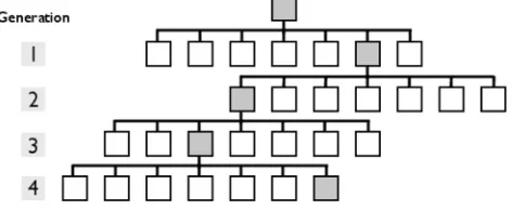
We employ a simple form of a genetic algorithm (GA) to perform the optimization, as summarized in Fig. 1. Generally, GA methods mimic the evolution of biological
species, in which populations evolve in generations, based on inheritance, mutation, and selection. Typically, a parent population would produce a larger set of offspring candi-dates from which a new generation is selected, based on some measure of fitness, with respect to selected traits. The traits of an individual are inherited from its parent(s) but vary by some stochastically determined degree and charac-ter. The selected new generation may be larger, smaller, or the same size as the parent population, but the average set of traits will evolve toward the fitness targets. This is a power-ful approach for optimizing physical systems, since such methods can probe large perturbations or mutation trajecto-ries that may span over multiple generations.
The GA scheme used here for EML coil optimization is very simple. The population consists of a single individual (a coil), for which the traits areri,zi,kiand the number of loops nin the coil. Employing random mutations from the traits of the parent coil, a generation of offspring candidate coils is produced, from which the next generation coil is selected, based on the optimization target of minimizing the lower bound of achievable temperatures, within the constraints listed previously. This selected best coil becomes the parent for the subsequent generation. The process is repeated for a fixed number of generations.
The variations that comprise each new generation of candidate coil offspring are produced by modifying the par-ent coil using a set of specific mutations, selected from a well defined range of possible mutations that represent three basic classes. These include (i) incrementing nby one, (ii) decrementing n by one, or (iii) adding a variation vector
dpi¼ ðdri;dziÞ to a randomly selected loop position,
pi¼ ðri;ziÞ. Simply stated, these involve the addition, dele-tion, or repositioning of a single loop, respectively. Assuming that the coil design is comprised only of co-axial circular loops, then these three mutations represent all of the changes that can be made in a single loop of the coil.
Regarding model execution, the deletion of a single loop is trivial and requires no explanation here. For the positional variation of an existing loop, illustrated in Fig. 2, a maxi-mum valuedpmaxis defined for the permitted variation of the individual position components, dri and dzi. Variations in position are randomly chosen within these limits. We stipu-late that no mutation can result in a physical overlap between two coils. We further constrainrito be greater than a
prede-termined global minimum (rmin), which permits the
estab-lishment of a minimum coil radius in accord with relevant practical experimental requirements. For example, the final coil must (i) be capable of accepting a silica tube for the use in secondary cooling, (ii) leave sufficient space for the intro-duction or extraction of the specimen, and (iii) offer an unob-structed view of the sample from above for temperature measurement. For mutations that increment n, the new loop position,zn0, is chosen randomly between the maximum and
minimum among all zivalues for the parent coil. Similarly,
the new radial position rn0 is selected at random over the
range of existing loop radii. Finally, the sense,ki, is selected
[image:5.612.58.294.627.724.2]for the new loop, based on its position relative to the mid-plane of the coil. As with the repositioning of a coil, the newly added coil must not overlap any of the existing coils. FIG. 1. A schematic representation of the GA approach is shown here. Each
generation is produced from a parent coil using a series of random mutations in the coil parameters. From each generation, the fittest coil is selected to become the parent for the subsequent generation.
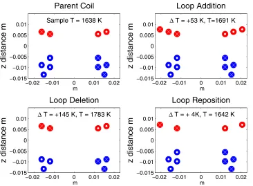
Among the three types, a mutation distribution of 10% decrement, 20% increment, and 70% repositioning was implemented. Specific examples of the possible mutation types and their effect on sample temperature are shown in Fig.3. It should be noted that the quantification of a mutation effect includes the recalculation of levitation forces, equilib-rium position, and associated steady-state temperature, as discussed in Sec.III.
III. ANALYTICAL MODEL
The optimization scheme requires a prediction of the temperature and positional stability of a statically levitated specimen for a given coil configuration and input current. The power absorbed by the specimen depends not only on the coil current but also on its position within the coil, which varies with input current and coil configuration. We employ an analytical model that includes: (i) the position-dependent heating effects of each coil loop, (ii) the magnetic forces
generated by each loop, and (iii) thermal losses from radiation and convection.
We base our analysis, initially, on the model of Fromm and Jehn10(FJ), who described the net axial force exerted on a specimen of radius,R, within the coil as
Fz¼3
2plJ
2
R3gð/ÞhðnÞ; (1)
where the coil geometry is generalized to be a series of n
coaxial circular loops, as depicted in Fig.4, and where
gð/Þ ¼1 3
4/
sinhð2/Þ sinð2/Þ
sinh2ð/Þ þsin2ð/Þ; (2)
hðnÞ ¼ X
n
i¼1
kir2 i
ðr2
i þ ðzziÞ 2
Þ3=2
!
X
n
j¼1
kjr2jðzzjÞ
ðr2
j þ ðzzjÞ 2
Þ5=2
!
; (3)
and
/¼Rpffiffiffiffiffiffiffiffiffiffipflc: (4)
The equilibrium specimen position is determined by the 1-D (axial) force condition, in which the upward coil lifting force, Fz, is equal to the downward gravitational force.
Stability of the sample within the coil requires that
dFz=dz<0.
[image:6.612.57.290.66.189.2]From the equilibrium specimen position within the coil, it is then possible to calculate the steady-state specimen temperature. Heating from the induced current is given by FJ10as
FIG. 2. Schematic of the coil geometry showing the imposed loop variation limits. The loop position is prohibited from the lined and shaded region of widthDminanddpiis restricted to the shaded region (radiusdpmax).
FIG. 3. Examples of the three possible mutation types and their effect on sample temperature, computed for pure copper in vacuum. All three mutated coils originate from the same parent coil (upper left).
[image:6.612.330.564.198.352.2] [image:6.612.51.417.498.767.2]_ qI ¼3
p3lf
c
1=2
R2 1
2J
Xn
i¼1
kir2 i
ðr2
i þ ðzziÞ 2
Þ3=2
" #2
: (5)
The radiative loss flux is given by the Stefan-Boltzmann law23
_
qR¼r4pR 2ð
T4T04Þ: (6)
The convective loss flux is given as a product of the heat transfer coefficient,h, the area of the sphere, and the temper-ature difference between the sphere and the fluid23
_
qC¼4pR2ðTTfÞh; (7)
wherehis given as
h¼ kf
2RNuf (8)
and the Nusselt number, Nuf, for a sphere is
Nuf ¼2:0þ0:6 2R1
qf
g
1=2
Cpg kf
1=3
: (9)
The relevant parameters are defined in TableI. The heat balance condition
_
q¼q_Iq_Rq_C¼0; (10)
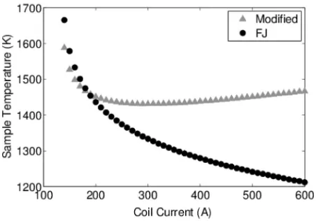
can be solved for the steady-state temperature. Fig.5shows the predicted behavior, based on the FJ equation for induced heating (Eq.(5)), for an aluminum sample (R¼5 mm) within a coil having the geometry shown in Fig. 4. Note that the sample temperature shows a steady decrease as the coil cur-rent is increased, which is not observed in practice.
A simplifying assumption made in the formulation of the FJ model is that the induced current is considered to flow only within a single current loop around equator of the spher-ical specimen. That assumption does not properly account for the spatial distribution of specimen mass within the coil configuration. To better account for the geometry, we treat the specimen as a series of m disk-shaped segments, each with a specific radius and axial position within the coil, and each acting as an independent heat receptor. The power absorbed by the sample is then computed by summing over all of the individual disks
_ qs¼
1
Vs
Xm
i¼1
Viq_i; (11)
where eachq_iis given byq_IðriÞ,Viis the volume of diski, and Vs is the total volume of the sample. A value of m¼15 000
[image:7.612.65.283.63.290.2]was used for all analyses reported here. The steady-state tem-peratures predicted with Eq.(11)are plotted in Fig.5as filled triangles. Note that the curve exhibits a temperature minimum, consistent with experimental observation.
FIG. 4. Generalized coil geometry used in the derivation of the levitation force. Each loop is specified by a sample radius,bn, and position,zn(adapted
from Ref.10).
TABLE I. Summary of model variables and constants.
Description Value Ref.
l Magnetic permeability 4p107H / m 10
f Frequency of coil 178 kHz
c Electrical conductivity 4.573106S / m 24
R Sample radius 5 mm
Emissivity of liquid droplet 0.1 23
r Stefan–Boltzmann constant 5:670108W=m2K4 10 T0 Temperature of surroundings 298 K
kf Thermal conductivity of fluid 152103W=ðm KÞ 25
v1 Fluid velocity, Ar 0.0184 m=s
g Kinematic viscosity 199107m2=s 25
qf Density of fluid 162.5 g=m3 26
Tf Fluid temperature 298 K
I Coil current 0-400 A
T Sample temperature
[image:7.612.314.561.75.284.2]bn Radius of coil loop n zn Axial position of coil loop n
FIG. 5. The unmodified model for sample temperature as presented by Ref.
10predicts a continuously decreasing sample temperature with increasing coil current (filled circles). The modified model shows a minimum in the sample temperature (filled triangles).
[image:7.612.325.551.564.722.2]IV. OPTIMIZATION RESULTS
Incorporating the analytical model described above into the GA scheme, we proceed to examine EML coil optimiza-tion with the target of minimizing the lower bound for the accessible steady-state temperature range for stable static levitation. To illustrate the method, we performed the opti-mization for an Al specimen in an Ar environment, with
R¼5 mm and properties shown in TableI. We used the coil design shown in Fig.6as the starting place in the optimiza-tion. This particular coil design has shown good levitation performance and has been analyzed for high temperature applications.12,14For the optimization, we used a total of 60 generations, each consisting of 40 variant offspring, which numerical tests showed to be sufficient.
Loop # zi(m) ri(m) ki
1 0.000 0.012 1
2 0.000 0.016 1
3 0.004 0.012 1
4 0.004 0.016 1
5 0.004 0.020 1
6 0.012 0.012 1
7 0.012 0.016 1
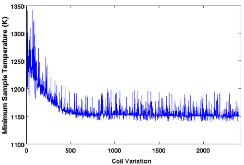
The evolution of the coil performance as measured by the minimum sample temperature is shown in Fig. 7 as a function of the total coil variation (i.e., 60 generations times 40 variants/generation). The predicted steady-state minimum temperature shows a total decrease of approximately 75 K relative to that of the starting coil design. Fig.8shows that the overall change in coil configuration was rather dramatic, with the final design having fewer loops and a generally cy-lindrical layout, characteristic of a solenoid, rather than the “pancake” style of the seed coil. The figure also shows that the evolution in geometry occurred mainly within the first ten generations, consistent with the rapid decrease of the steady-state temperature, shown in Fig.7.
V. EXPERIMENTAL COMPARISON
[image:8.612.319.558.61.223.2]Through comparison with experimental levitation, we verify the predictive capability of the model and evaluate the performance gains (both predicted and realized) associated with the optimization process. The coils were fabricated from copper tubing (with 3:2 mm outer diameter and 1:6 mm inner diameter). Levitation experiments were performed using the same parameters and range of applied current as used for the optimization. Fig. 9 shows the comparison between the measured sample temperatures and those pre-dicted by the model, for the two coils over the full current
FIG. 6. The starting coil geometry used in the test optimization. Given are the values ofzi,ri, and tki, which represent the z-position, the radius, and
the sense of the loop, respectively. Also shown is a diagram of the coil, with the bottom loops (X symbol on right) having a clockwise coil direction (sense¼1) and upper loops (X symbol on left) an anti-clockwise direction (sense¼ 1), viewed from below.
[image:8.612.316.560.426.737.2]FIG. 7. The results of optimization for an Al sample (r¼5mm) in a low flow (Vg¼18:4 mm=s) of Ar.
FIG. 8. The evolution of the coil design over the 60 generations is presented using the optimal coil design from 7 generations.
[image:8.612.58.292.527.702.2]range. We note that the overall behavior is well modeled, with predicted sample temperatures generally within approx-imately 30 K of the measured values. While this deviation is relatively small on the absolute scale of the sample tempera-ture (roughly 1000C), it is important to assess the likely sources of error. Examination of Eqs. (1)–(7) suggests that there are three likely sources of error, including (i) uncer-tainty in the specimen emissivity (required for infrared pyro-metry measurements of sample temperature), (ii) inaccurate temperature dependence of material parameters used in the model (e.g., c, kf), and (iii) imperfections in the physical
coils or deviations from the idealized geometries used in the model. In our temperature measurements, we used an emis-sivity value of 0.1 for a pyrometer operating at 1.55lm. This value was based on measurement of the equilibrium melting temperature of aluminum,27but we note that there is insuffi-cient information to indicate the accuracy of this value over a range of temperatures. Equation(5) describes the depend-ence of the power absorption on materials constants, specifi-cally emissivity and conductivity. Being independent of the levitation current, variations in these parameters are likely to lead to relatively uniform temperature changes across the current range, consistent with the type of error observed. Regarding the coil geometry, the model is based on describ-ing the coil as a series of co-axial loops. The actual coil, however, has a helical shape.
To more closely examine the magnitude of the optimization-based performance gains relative to the general sensitivity of coil performance to unsystematic variability among coils of the same design, two identical coils were constructed and tested over the optimization range. The ex-perimental results can be seen in Fig.10. The inherent noise in building an identical coil was determined to be small, an average difference of 8C between the two coils was meas-ured, which is small compared to the signal being studied (75 optimization). The experimental comparison between the seed and optimized coil (Fig. 9) clearly shows the improved performance of the optimized coil, which exhibits
a minimum sample temperature that is approximately 70 K lower than that of the seed coil. Again, we note that the opti-mization scheme applied here was specifically targeted to-ward reduction in sample temperature, but that other optimization criteria could certainly be employed.
While we have not done an exhaustive analysis of the possible errors, we found that differences in the predicted and experimental temperatures can be accounted for by a 7% decrease in the sample conductivity. Such a variation is cer-tainly possible, given that the experimental sample tempera-tures are at least 300 higher than the temperature used to determine the tabulated values presented in TableI. Despite these small errors, two particularly noteworthy points are clearly demonstrated by Fig. 9. First, the model correctly captures the overall effect of input coil current on the sample temperature, with the temperature exhibiting a minimum at a specific current, a feature that could not be predicted without the modification to the model for absorbed power shown in Eq. (11). Second, with regard to this minimum in the current-temperature behavior, the model accurately predicts the difference arising from the change in the coil geometry. The excellent agreement between experiment and modeling gives credence to the optimization strategy, showing the power of this approach for finding optimized coil designs.
VI. DISCUSSION
In the preceding sections, we outlined a general genetic-algorithm optimization scheme for EML coil design, targeted towards achieving a minimum in the lower bound for the range of stable static levitation temperatures. We validated the procedure by experimentally constructing and testing the designs. In this section, we examine the sensitivity of an optimized design on starting conditions, based on a number of coil designs. These designs were created by varying the principal components, n, ri, andzi, to create a set of initial
[image:9.612.318.558.61.229.2]coil configurations found in the literature, as described in Fig. 11. Specifically, we consider a pure copper sample (based on the parameters in TableII) and relax the constraint FIG. 9. The effect of the coil current on sample temperature (solid lines)
[image:9.612.54.295.63.241.2]compares favorably to the experimental results when the temperatures are shifted uniformly across the entire current range. Error bars are representa-tive of measured temperature variation for500 measurements.
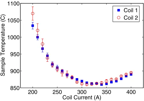
FIG. 10. The inherent variability in construction of two identical coils was analyzed by determining the sample temperature as a function of coil cur-rent. Error bars are representative of measured temperature variation for
500 measurements.
that the levitation condition must be at least as stable as that produced by the seed. This criterion, while useful in the prac-tical design of a new levitation coil, makes comparison across a range of starting conditions difficult, since the applied constraint would vary between the initial designs. We have also chosen to simplify the system by considering levitation in a vacuum rather than in an inert atmosphere, eliminating the convective heat loss described in Eq.(7)and thus the need for fluid parameters.
For each starting design in Fig. 11, sixteen independent optimization trials were completed with outcomes summar-ized in Fig.12(a). For the complete set of 64 trials, the aver-age final number of loops is 7.2 (3.0 upper and 4.2 lower), with the most probable configuration (the mode) having
n¼7 (3 upper and 4 lower). Out of the 64 trials, a total of 45 final configurations included 7 loops, and the loop locations for these optimized coils are shown in Figure 12(b). The results reveal strong clustering of the loop positions around the average locations, which are shown for each loop by the open circles in Fig.13. The average loop positions are also listed in TableIII. To quantify the overall variability among coils, the total deviation from this average configuration was computed for each 7-loop coil as
dTk ¼
X7
i¼1
ffiffiffiffiffiffiffiffiffiffiffiffiffiffiffiffiffiffiffiffiffiffiffiffiffiffiffiffiffiffiffiffiffiffiffiffiffiffiffiffiffiffiffiffiffiffiffiffiffiffiffiffi
ðrik hriiÞ2þ ðzik hziiÞ2
q
[image:10.612.50.387.61.310.2]; (12)
FIG. 11. A range of starting coils used to test the sensitivity on starting conditions. The coils in (a)–(d) were taken selected from Refs.11,12,14, and28, respectively.
[image:10.612.325.550.310.744.2]FIG. 12. Summary of optimized coil loop positions (a) for all optimization trials, and (b) for subset of trials containing 7 total loops.
TABLE II. Summary of material parameters for pure copper.
Description Value Ref.
l Magnetic permeability 4p107 10
c Electrical conductivity 4.997106S 24
q Liquid Density 8.02106g=cm3 23
Emissivity of liquid droplet 0.14 23
[image:10.612.50.296.692.764.2]whererik andzikare the positions of the ith loop in the kth
coil andh iindicate the average over all coils. The distribu-tions ofdT
k for each of the 7 loops are shown in Fig.14.
The loop locations shown in Fig. 13 include all coil designs for whichdT
i is within two standard deviations of the
mean. We see from that figure that there is very little varia-tion in three of the seven loop posivaria-tions (labeled as 2, 4, and 5), while the others (labeled as 1, 3, 6, and 7) exhibit a larger degree of variation. Moreover, the highly directional nature of spatial variation shown in Fig.13suggests the presence of a relatively uniform low-divergence gradient field for the specimen temperature with respect to coil position.
VII. CONCLUSIONS
We have developed and presented here a genetic algo-rithm approach to EML coil design. Into this approach, we have incorporated an analytical model for inductive heating and levitation, which we modified to account for geometrical effects, giving more realistic response than previous models. Further, we have demonstrated the model using an example where a minimum in the levitated specimen temperature is desired. From our results and analysis, we draw the follow-ing conclusions:
(i) The optimization procedure is robust, yielding con-verged results from a variety of starting conditions. (ii) The approach is general and can be used to optimize
coil performance based on selected properties. (iii) The method provides an effective way to develop new
coil designs that operate within the restrictions of a
laboratory levitation system (i.e., physical or opera-tional restrictions).
(iv) The method can be used specifically to produce a coil design for the reduced temperature levitation of liquid aluminum, a result that we verified experimentally. This serves as an example of how EML coil design can be conducted to attain specific performance tar-gets despite the challenges associated with the strong coupling between heating and levitation forces arising from the induced current.
ACKNOWLEDGMENTS
[image:11.612.315.560.55.524.2]This work was supported by the US Department of Energy,Office of Basic Energy Science, Division of Material Sciences and Engineering. The research was performed at Ames Laboratory, Ames Laboratory is operated for the US FIG. 13. Shown are the optimized coil designs for which the total variation
distancedT
i is less than two standard deviations of the mean away from the average coil positions (indicated with the black circles).
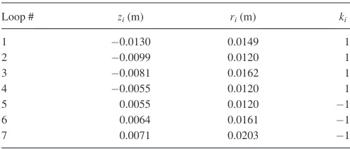
TABLE III. Mean loop positions forn¼7 coils (Cu in vacuum).
Loop # zi(m) ri(m) ki
1 0.0130 0.0149 1
2 0.0099 0.0120 1
3 0.0081 0.0162 1
4 0.0055 0.0120 1
5 0.0055 0.0120 1
6 0.0064 0.0161 1
[image:11.612.56.293.62.215.2]7 0.0071 0.0203 1
FIG. 14. Distribution of loop position variation (dT
k) for each of 7 positions.
[image:11.612.50.297.660.765.2]Department of Energy by Iowa State University under Contract No. DE-AC02-07CH11358. The authors would like to thank Dr. Nicola Bowler for valuable discussions in the development of this work.
1J. Brillo, I. Egry, H. S. Giffard, and A. Patti, “Density and thermal
expan-sion of liquid Au-Cu alloys,” Int. J. Thermophys. 25(6), 1881–1888 (2004).
2Y. Plevachuk, I. Egry, J. Brillo, D. Holland-Moritz, and I. Kaban,
“Density and atomic volume in liquid Al-Fe and Al-Ni binary alloys,” Int. J. Mater. Res.98(2), 107–111 (2007).
3
J. Treverton and J. L. Margrave, “Levitation calorimetry. IV. Thermodynamic properties of liquid cobalt and palladium,” J. Phys. Chem.75(24), 3737–3740 (1971).
4
K. Zhou, H. P. Wang, J. Chang, and B. Wei, “Specific heat measurement of stable and metastable liquid Ti-Al alloys,” Appl. Phys. A 103(1), 135–137 (2011).
5K. Zhou, H. P. Wang, and B. Wei, “Determining thermophysical
proper-ties of undercooled liquid Ti-Al alloy by electromagnetic levitation,”
Chem. Phys. Lett.521, 52–54 (2012).
6J. Brillo, I. Egry, and T. Matsushita, “Density and surface tension of liquid
ternary Ni-Cu-Fe alloys,”Int. J. Thermophys.27(6), 1778–1791 (2006).
7
D. M. Herlach, “Non-equilibrium solidification of undercooled metallic melts,”Mater. Sci. Eng. R12, 177–272 (1994).
8D. M. Herlach, “Containerless undercooling and solidification of pure
met-als,”Ann. Rev. Mater. Sci.21, 23–44 (1991).
9
E. C. Okress and D. M. Wroughton, “Electromagnetic levitation of solid and molten metals,”J. Appl. Phys.23(5), 545–552 (1952).
10E. Fromm and H. Jehn, “Electromagnetic forces and power absorption in
levitation melting,”Bri. J. Appl. Phys.16(5), 653–659 (1965).
11
S. Jahanshahi and J. H. E. Jeffes, “Design of coils for levitating droplets of metals with improved temperature control characteristics,” Trans. Inst. Mining Metall. Sec. C90(DEC), C138–C141 (1981).
12Z. A. Moghimi, M. Halali, and M. Nusheh, “An investigation on the
tem-perature and stability behavior in the levitation melting of nickel,”Metall. Mater. Trans. B37(6), 997–1005 (2006).
13M. G. Frohberg, “Thirty years of levitation melting calorimetry—a
bal-ance,”Thermochim. Acta337(1-2), 7–17 (1999).
14
A. Kermanpur, M. Jafari, and M. Vaghayenegar, “Electromagnetic-ther-mal coupled simulation of levitation melting of metals,”J. Mater. Process. Technol.211(2), 222–229 (2011).
15G. Tang, P. Lin, C. Xu, J. Xue, T. Liu, Z. Wang, and X. Li,
“Optimal selection for multiple quantitative trait loci and contributions of individuals using genetic algorithm,” Livestock Sci.141(2-3), 242–251 (2011).
16A. M. Abazari, M. Solimanpur, and H. Sattari, “Optimum loading of
machines in a flexible manufacturing system using a mixed-integer linear mathematical programming model and genetic algorithm,”Comput. Ind. Eng.62(2), 469–478 (2012).
17S.-H. Chen, P.-C. Chang, T. C. E. Cheng, and Q. Zhang, “A self-guided
genetic algorithm for permutation flowshop scheduling problems,”
Comput. Operat. Res.39(7), 1450–1457 (2012).
18
J. R. Cho, J. H. Lee, K. M. Jeong, and K. W. Kim, “Optimum design of run-flat tire insert rubber by genetic algorithm,”Finite Elem. Anal. Design 52, 60–70 (2012).
19
F. M. Gonzalez-Longatt, P. Wall, P. Regulski, and V. Terzija, “Optimal electric network design for a large offshore wind farm based on a modified genetic algorithm approach,”IEEE Syst. J.6(1), 164–172 (2012).
20
Y.-K. Lin and C.-T. Yeh, “Multi-objective optimization for stochastic computer networks using NSGA-II and topsis,” Eur. J. Operat. Res. 218(3), 735–746 (2012).
21H. Nazif and L. S. Lee, “Optimised crossover genetic algorithm for
capaci-tated vehicle routing problem,” Appl. Math. Modell.36(5), 2110–2117 (2012).
22
S. Suzuki and Y. Mitsukura, “Evolutionary structure optimization of hier-archical neural network for image recognition,”Electron. Commun. Jpn. 95(3), 28–36 (2012).
23
D. R. Poirier and G. H. Geiger, Transport Phenomena in Materials Processing (Minerals, Metals & Materials Society, Warrendale, Pa., 1994).
24
W. K. Rhim and T. Ishikawa, “Noncontact electrical resistivity measure-ment technique for molten metals,”Rev. Sci. Instrum.69(10), 3628–3633 (1998).
25Y. S. Touloukian, R. W. Powell, and C. Y. Ho,Thermophysical Properties of Matter(Plenum, New York, NY, 1970).
26
J. Hilsenrath, C. W. Beckett, W. S. Benedict, L. Fano, H. J. Hoge, J. F. Masi, R. L. Nuttall, Y. S. Touloukian, and H. W. Woolley, Tables of Thermal Properties of Gases(NBS Circular 564, 1955).
27K. Ohsaka, J. R. Gatewood, and E. H. Trinh, “An apparatus for the
specific-heat measurement of undercooled liquids,” Scr. Metall. Mater. 25(6), 1459–1464 (1991).
28L. R. Weisberg, “Levitation melting of Ga, In, Au, and Sb,” Rev. Sci.
Instrum.30(2), 135 (1959).