Please cite this article as: M. Rastgar, H. Showkati, Field Study and Evaluation of Buckling Behavior of Cylindrical Steel Tanks with Geometric Imperfections under Uniform External Pressure, International Journal of Engineering (IJE), TRANSACTIONS C: Aspects Vol. 30, No. 9, (September 2017) 1309-1318
International Journal of Engineering
J o u r n a l H o m e p a g e : w w w . i j e . i rField Study and Evaluation of Buckling Behavior of Cylindrical Steel Tanks with
Geometric Imperfections under Uniform External Pressure
M. Rastgar*, H. Showkati
Department of Civil Engineering, Urmia University, Urmia, Iran
P A P E R I N F O
Paper history:
Received 24 February 2017 Received in revised form 25 June 2017 Accepted 07 July 2017
Keywords: Field Study Buckling Behavior External Pressure Cylindrical Tank Geometric Imperfection
A B S T R A C T
Construction and assembling process of shell structures has caused main problems. In these structures, there is no possibility for the integrated construction due to their large shell extent and they are built using a number of welded curved panel parts; hence, some geometrical imperfections emerge. Most of these imperfections are caused by the process of welding, transportation, inappropriate rolling, as well as installation and implementation problems. In this research, construction of steel cylindrical tanks in one of the refinery site is monitored using a field survey and created imperfections are identified and introduced. Relying on the statistical inference, they are classified and then, by studying the effective factors and origin in their generation, the common imperfections are identified. The impact of common imperfections on the buckling behavior is experimentally evaluated under uniform external pressure. Then, nonlinear analysis of the test specimens are performed by ANSYS software. Finally experimental results, finite element and analytical relations are compared. The obtained results show that the imperfections have a direct impact on the structural behavior of shells during the buckling under uniform external pressure load. Also, some imperfections caused by welding increase the buckling resistance of cylindrical shells.
doi: 10.5829/ije.2017.30.09c.03
1. INTRODUCTION1
Shell structures have curved initial shapes with the thickness so much less than two other dimensions. In some states, radius to thickness ratio reaches 3000. Among the most common methods for strength increase without weight increase is the use of thin walled shell structures, which have important and beneficial properties owing to their useful structural form and light weight with high strength. The stability type of a structural system depends on parameters such as geometrical properties as well as materials and environmental conditions such as loading conditions. Instability is theoretically defined as bifurcation point, limit point and dynamic and vibration instability. Several studies about buckling behavior and instability of shells have been done which can be pointed as follows:
*Corresponding Author’s Email: [email protected] (M. Rastgar)
pressures of thin-walled cylinders was theoretically discussed by De Paor et al. [8]. Buckling analysis of composite lattice cylindrical shells with ribs defects was studied by Akbari Alashti et al. [9]. Ghazijahani et al. [10] studied longitudinally stiffened corrugated cylindrical shells under uniform external pressure. Kalantari and Razzaghi [11] predicted the buckling capacity of steel cylindrical shells with rectangular stringers under axial loading by using artificial neural networks.
2. GEOMETRIC IMPERFECTIONS
Imperfections are generally divided into four groups of geometrical imperfections, loading imperfections, imperfections due to boundary conditions, and imperfection associated with physical properties of materials [12]. Geometrical imperfections include all the deviations in the form of structural component compared with its ideal geometrical composition. In the construction of shells, due to the large dimensions, curved plates or panels can be used. The seam between various plates of the main source of deviation is in the real form, these deviations or imperfections can be generated as a result of welding or appropriate incompatibility of the plates with larger dimensions than other plates. In some states, geometrical imperfections may strengthen the structure and increase its capacity [10]. Several studies about imperfection influence on the buckling behavior and instability of shells have been done which can be pointed as follows:
Abramovich et al. [13] investigated repeated buckling and its influence on the geometrical imperfections of stiffened cylindrical shells under combined loading. Also, in this year buckling loads of tank shells with imperfection was discussed by Hornung and Saal [14]. Khamlichi et al. [15] investigated buckling of elastic cylindrical shells considering the effect of localized axisymmetric imperfection. Imperfection influence on the buckling of thin cylindrical shell under uniform external pressure was studied by Lo Frano and Forasassi experimentally [16]. Yang et al. [17] studied buckling of cylindrical shells with general axisymmetric thickness imperfections under external pressure. Inelastic stability of liners of cylindrical conduits with local imperfection under external pressure was studied by Khaled El-Sawy [18]. Ghazijahani et al. [19] done experiments on dented cylindrical shells under peripheral pressure.
3. WELDING IMPERFECTIONS
Steel tanks and silos are considered among the thin-walled structures which are usually constructed by
welding a large number of curved panel components to each other. Panels are welded using meridional welding to form vertical paths and attached floors as well as circular and continuous environmental welding for complete shaping of the welding shell wall. Due to the large number of welds, both deformations caused by welding and residual stresses have a significant impact on the buckling strength of the shell wall [20].
In Figure 1, the buckling behavior of columns, flat plates and cylindrical shells are schematically shown. In these curves, highlighted lines show the system with no geometric imperfections or perfection, while thin lines represent the corresponding behavior of the imperfect system. As can be seen, the bar and plate elements are not sensitive to imperfection, while cylinders which are the examples of thin-walled structures are very sensitive to imperfections [21].
Several studies about weld-induced imperfections influence on the buckling behavior of shells have been done that can be pointed as follows:
Maali et al. [20] investigated the Buckling behavior of conical shells under weld-induced imperfections experimentally. Teng et al. [22] investigated the geometric imperfections in full-scale welded steel silos. In other work, buckling behavior of large steel cylinders with patterned welds was considered by Hubner et al. [23].
4. ANALYTICAL EQUATIONS FOR BUCKLING OF CYLINDRICAL SHELLS
Stability equation of cylindrical shells has been derived as follows:
The general solution of this equation is as follows:
x c x c x c n
c
w(1sin 2cos 3 4)sin (2)
In which
L m n
m, 1,2,3,...,
Figure 1. Load-axial displacement graph of bars, plates and
shells in perfect and imperfect states [24]
0 ) , ( 4 ,
8
wxxxx Nw R
Et w
Using the boundary conditions, c1 to c4 constants are obtained. Considering simple end conditions for the cylindrical shell as well as m=1, uniform external pressure buckling load is calculated as follows [24]:
The number of circumferential waves of cylindrical shell formed in the body of the tank is as follows [2]:
Considering the application of uniform external pressure to the roof of cylindrical tanks causes a uniform axial force to the body of tanks, and the buckling load of these tanks under the simultaneous effect of uniform lateral pressure and axial load is obtained by the following equation [24].
) 2 5 . 0 2 ( 2 ) 2 2 ( ) 2 1 ( 4 ) 2 ( 4 ) 2 2 ( 1 m n n m C m R D n m R cr P (4) t R L R t R R L
N 4 2.74 ) ( 2 ) ( 2 1 2
6
(5)
) 2 1 ( , ) 2 1 ( 12 3 Et C Et D (6)
In these equations:
D Bending stiffness of plate. w Deflection in the z-direction. E Modulus of elasticity.
Poisson's ratio.
t Thickness of cylindrical shell. R Radius of cylindrical shell. L Height of cylindrical shell.
N Axial load in the -direction.
m Number of waves in the z-direction. n Number of waves in the -direction.
cr
P Buckling load.
N Number of circumferential waves in the buckling situation.
5. FIELD SURVEY
In order to store oil products in a refinery site located in the industrial town of Julfa free zone, the construction of numerous tanks has begun, which are being implemented as steel cylindrical tanks in 2 different sizes:
The first type of tanks has the height of 12 m, diameter of 23 m, and sheet thickness of 18 mm and 3 of them are under construction. The second type of tanks has the height of 7.5 m, diameter of 13.5 m, and sheet thickness of 14 mm and 5 of them are under
construction. For the construction of these tanks, the steel sheets with the dimensions of 6×1.5 m and thickness of 18 and 14 mm are used. These sheets are entered into the rolling device and the curvature operations are performed during several steps to reach the radius of the tank. Then, their installation operations are carried out using the crane and human force. From this step on, numerous imperfections caused by various implementation factors are made. The steps are shown in Figure 2.
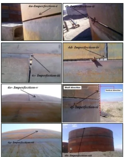
As shown in this figure, the edges of the circumferential sheets do not match each other. These edges should get close to each other by a chain and a crane until the imperfection is modified. According to this figure, the rolled sheets are put in their place by the crane and then temporarily welded next to each other. When the first layer is completed, the next layers are implemented similar to the first layer. In this research, after attending the tank implementation location and field monitoring of the installation of circumferential sheets, various type of imperfections are observed. These imperfections which are shown in Figure 3, are classified as follows:
Figure 2. Circumferential sheets installation process in the
body of tank and generation of different imperfections
Figure 3. Types of observed imperfections in the field study
1- Imperfection I: Non-compliance to the edges of the consecutive horizontal rows that occurred outside and inside.
2- Imperfection II: Vertical seam isn't executed properly and is sharp towards inside or outside.
3- Imperfection III: Vertical edges aren't parallel. 4- Imperfection IV: Horizontal edges aren't aligned. 5- Imperfection V: Caused by unsuitable rolling 6- Imperfection VI: Different layers aren't vertical. 7- Imperfection VII: Effect of welding temperature which usually appears in the form of circumferential.
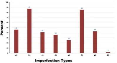
8- Imperfection VIII: Wind Effects causing troughs or bulge, in the peripheral of latest layer of tank. By continuing the field study on the implementation of these tanks in a 5-month period and statistical inference from the imperfections, the frequency distribution graph of the imperfections is drawn, as shown in Figure 4. In this figure, the horizontal axis shows the type of imperfection and the vertical axis is the frequency percentage of the corresponding imperfection. Accordingly, it can be seen that, from among all the introduced imperfections, imperfection types 2 and 6 occur more frequently than others, respectively.
6. EXPERIMENTAL PROGRAM
For the experimental evaluation of the impact of imperfections on the buckling behavior of tanks, two experimental specimens were built with the following characteristics:
The first specimen named that Spec1 has the diameter of 1.15 m, height of 0.6 m, conical roof with the height of 0.2 m, body plate thickness of 1 mm, and floor and roof thickness of 1.5 mm in an integrated form. Due to the limited length of the used plates which is 3 m and providing for the 3.6 m perimeter of this specimen, there are two vertical welding lines in the body of tank. The weld line is perfectly circular and has no dents or bumps. Despite high accuracy in producing this experimental specimen, some local imperfections emerge; the major one includes imperfections caused by welding. The local imperfections may also affect buckling behavior of tanks.
Figure 4. Frequency distribution graph of the imperfections
The second specimen named that Spec2 has the diameter of 1.15 m, height of 0.6 m, conical roof with the height of 0.2 m, tank body plate thickness of 1 mm, and floor and roof thickness of 1.5 mm in panelized form; each panel which has the dimensions of 300×75 mm as well as 12 panels in the circumference and 8 stages in height, in total, it has 96 panels. This specimen has been implemented similar to real tanks and most introduced imperfections such as type 1, 2, 5, 6 and 7 are available in this specimen therefore simultaneous impact of the imperfections is examined on buckling behavior under uniform external pressure.
These specimens are shown in Figure 5. Their size is selected on the scale of 1:20 compared to real tanks in accordance with existing lab facilities. Welding on experimental models is quite different from real tanks. These specimens are welded using CO2.
In order to prevent the floor and roof buckling of these tanks influenced by external pressure, strengthening straps with the section of 20×5 mm are used. These straps could increase the bending stiffness in the roof and floor of the tanks; so, under the uniform external pressure, these two parts maintain their initial situation and do not buckle as a result, only the body of the tanks starts to move and buckles.
7. TESTING OF SPECIMENS AND EVALUATION OF RESULTS
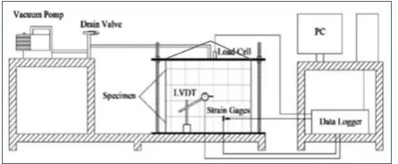
7. 1. Uniform External Pressure Loading In order to evaluate the buckling behavior in the experimental specimens influenced by uniform external pressure, the suction device is used. It is an electro-pump device that discharges the air inside the tank to the outside. So, by discharging the inside air, the atmospheric pressure is uniformly imported into the external surfaces of this tank and loading is applied as uniform external pressure.
Figure 5. Experimental specimens: (a) Spec1 in an integrated
form (b) Spec2 in panelized form
(a )
Since air discharge flow of the tank is too high, it is necessary to embed a control valve to adjust the discharge flow and thus control the external pressure. In Figure 6, the laboratory equipment, including the suction pump for loading application, loading control valve, loading measurement device, deformation measurement devices, location of test samples, the data logger, and the computer are schematically shown. In order to measure the internal pressure in the tank, a pressure gauge is used.This device shows the pressure inside the tank, which is decreased due to the discharge by the suction device.
So, the external pressure is obtained by subtracting atmospheric pressure and the internal pressure of the tank. There are three holes in the tank floor: the first hole is connected to the suction device, through which discharge operation is done (applying uniform external pressure). The second hole is connected to the discharge valve and controls the flow of tank discharge (loading control) and the third one is connected to the pressure gauge to measure the internal pressure (loading measurement).
7. 2. Test Procedure and Measurement Devices In order to take the experimental specimens deformation, measurement devices are installed in different parts of these specimens in the middle of the height radially and also at the top of the conical roof of the specimens. In Figures 7a and 7b a sample of measurement devices and schematic view of all installed sensors is represented.
These devices include LVDT, strain gauge and pressure sensor. LVDTs take the directional displacements vertically, horizontally, or radially in the location they are installed and send them to the data logger. The strain gauges are the electronic circuits that are attached using a special adhesive in the desired location and measure strain in their installed direction and send it to the computer. In this research, in all the tests, five LVDTs and two horizontal and vertical strain gauges are used to record the deformation of different parts of the experimental specimens.
7. 3. Test Implementing By turning on the suction pump device air discharge started from Spec1
Figure 6. Schematic view of laboratory equipment's
(a)
(b)
Figure 7. (a) Installation of measurement devices on the
specimen. (b) Schematic view of all installed sensors
and the difference between the internal and external pressure of the tank was gradually increased. As a result, external pressure was gradually applied to the tank and the initial buckling of the tank body began. By increasing the external pressure, the number of the waves formed in the tank body was also increased and the tank moved toward full buckling. Then, after making 12 waves in the tank, the buckling of the body became complete and, finally, at the external pressure of 21.6 kPa, the tank failure suddenly happened and became instable. Figure 8 shows full buckling and Figure 9 demonstrates instability and failure of the experimental Spec1.
In the Spec2, similar to Spec1, loading continues gradually and in a controlled manner to the trough stage and full instability.
Figure 9. Failure of the experimental Spec1
In this specimen, in contrast to the previous sample, the circumferential waves are formed irregularly and randomly at different points of the tank body.
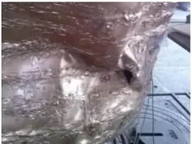
Finally, without completing the circumferential waves and getting the tank to the full buckling state, one of the circumferential panels becomes instable at the external pressure of 21.84 kPa due to the vertical weld line failure. In Figures 10 and 11, the instability and weld line failure of the experimental Spec2 are shown.
According to these figures, the instable form of Spec2 is completely different from that of Spec1 and no regular circumferential waves can be seen in the tank body as Spec1. In other words, full buckling in the Spec2 is not observed; but, due to the weakness of the vertical weld line in one of the panels, local buckling occurs, which makes the whole tank instable.
If the weld line did not fail, a higher buckling load than Spec1 was expected to be obtained. However, in the current state, the buckling load caused by the external pressure of this specimen shows a higher value than Spec1. The reason is the existence of welded lines in the panels composing the tank body, which increased the membrane strength of the tank against the
Figure 10. Instability of the experimental Spec2
Figure 11. Weld line failure of the experimental Spec2
compressive loads, similar to the circumferential stiffeners.
7. 4. Evaluation of Experimental Results By taking the data obtained from the measurement devices installed at different parts of these tanks, strain and radial displacement graphs of these points are drawn relative to the applied external pressure. Figure 12 shows the horizontal strain diagram in terms of external pressure at the half of the body height of Spec1 and Spec2 at the location of LVDT3. Horizontal strains show the circumferential deformations of the tank. Spec1 at point A bears 5 kPa load and has considerable strain changes.
The tank body locally buckles at this point and a leap can be seen on the graph from A to B, while Spec2 has no strain changes at these points and is almost without any strain to the load of 14 kPa or point F. This issue shows better initial strength of Spec2 than Spec1. Spec1 represents no great strain changes from points B to C. Finally, it becomes instable at point D and, then, from points D to E, it is located in the unloading state.
In Spec2, from points F to G, considerable strain changes can be observed. At point G, the direction of the strains is changed by continuing the loading and the tank body moves to the opposite side to reach point H and become instable. Then, the specimen is located in the unloading state to get the pressure inside Spec2 to the atmospheric pressure. In this specimen, permanent strains are left (point I), but their value is almost twice as much as that of Spec1
Figure 13 shows the radial displacement of the body of Spec1 and Spec2 at the location of LVDT3 in terms of external pressure. This point is almost close to the buckling and instability location of these specimens.
Spec1 shows no significant radial displacement from the start of loading to point A. From points A to B, a leap can be seen in the graph which is related to the local buckling of LVDT3 site. From points B to C, with an increase in the external pressure, the radial displacement is also increased and reaches 12 mm at point C.
Figure 12. Horizontal strain diagram of Spec1 and Spec2 at
Figure 13. Radial displacement of the body of specimens at the location of LVDT3 in terms of external pressure
Then, the tank suddenly becomes instable and the unloading step is started. But, radial displacement is also increased to reach 20 mm at point E. Afterwards, due to the instability at the adjacent points, the radial displacement is decreased until the external pressure reaches 0 at point F and the radial displacement of 4 mm is remained in Spec1.
In Spec2, with the start of the external pressure, less radial displacement can be observed compared with tank 1 until becoming 5 mm at point H. Then, direction of the radial displacement is changed and displacement continues in the opposite direction with the loading continuation until instability and failure of Spec2 occur at point G suddenly as a result of the weld line failure in one of the panels. From this step on, unloading is started and finished at point K. By comparing these graphs, it can be seen that the LVDT3 displacement from Spec1 at the instable moment is maximum 13 mm and then, during the unloading, it is about 20 mm at point D.
For Spec2, it is maximum 5 mm at point H. It is obvious that the membrane strength in Spec2 is more than that of Spec1 at the moment of buckling and failure, because the welding lines of the panels composing the body of Spec2 increase the membrane strength similar to circular stiffeners. In this research, vertical displacement in the conical roof of the specimens is also considered, which is shown in Figure 14 in terms of the applied external pressure.
The maximum roof displacement for Spec1 and Spec2 is almost 26 mm (point B) and 11 mm (point A) which is approximately 2.5 times, respectively.
Figure 14. Vertical displacement in the conical roof of the
Spec1 and Spec2 in terms of external pressure
This subject indicates that bending resistance of Spec2 is more than Spec1 in the z-direction that can be caused by vertical welding lines. These lines act as longitudinal stiffeners.
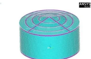
8. FINITE ELEMENT ANALYSIS
In order to evaluate the buckling behavior of the test specimens, numerical modeling of the specimens are carried out by the finite element software ANSYS V.16. Modeling of Spec1 named that Fesp1 is performed as a continuous sheet and Spec2 named that Fesp2 is panelized with the sheet thickness of 1 mm and thickness of 1.5 mm in the floor and roof. Similar to the experimental specimens, in order to prevent the buckling of the roof and floor, stiffeners quite similar to the specimens made in the laboratory are used.
The selected element of these models is Shell181. This element has 6 degrees of freedom and nonlinear properties. These models have acceptable mesh sizes so that elements of the model are 25×25 mm. Given such
mesh size, there would be 10,000 elements
approximately in each model. In Figures 15 and 16, finite element model and loading of Fesp1 and Fesp2 are demonstrated.
In this study, the nonlinear analysis of buckling including geometric nonlinearity and material nonlinearity is carried out for the Fesp1 and Fesp2 models. In Figure 17, nonlinearity model of material used in FEM (steel) is shown. As can be seen, the chart consists of 2 parts. The first part is related to the steel yield stress with the amount of 240 MPa and the second part is related to the nonlinear behavior of steel materials.
In Figures 18a and 18b, full buckling of the Fesp1 and local buckling of Fesp2 are shown before instability in the nonlinear state.
As can be seen, 12 full waves are created in the circumference of the Fesp1 and only 2 waves are created in the circumference of the Fesp2. In the experimental state, after full buckling and before the instability of Spec1, 12 waves are formed in the body of the Spec1 and 1 wave is formed in the body of the Spec2, so a good correspondence can be observed.
Figure 16. FEM model and loading of Fesp2 in ANSYS
Figure 17. The nonlinearity model of material used in FEM
Figure 18. (a)Full buckling of Fesp1 (b) local buckling of
Fesp2 and instability threshold
By drawing the load-displacement diagram at various points such as LVDT3 location, which is the location of failure and instability of the experimental specimens, the approximate value for the external pressure leading to the buckling of Fesp1 and Fesp2 is determined. Figure 19 shows the load-displacement graph of the Fesp1 and Fesp2 models.
In Fesp1 with the start of loading, small deformations start in the body of the tanks to point a. Then, by increasing the external pressure, radial deformations significantly increase to reach 11 mm at point b.
The oscillations in the graph of Fesp1 in the b-c zone show the formation of the circumferential waves around the studied point. At point c, the buckling of the tank body is completed at the pressure of 23 kPa and 12 full waves are created. Afterwards, by increasing the
loading, Fesp1 enters the post-buckling step and continues until the pressure of 30 kPa, while the post-buckling step is not seen in the experimental Spec1 and the specimen becomes instable after point c. Therefore, point a shows the start of the buckling of Fesp1 at the load of 16 kPa, point b shows the initial buckling of the specimen at the load of 21 kPa, the range b-c demonstrates the buckling of other points, point c shows the full buckling at the pressure of 23 kPa, c-d zone is the post-buckling step of the specimen to the pressure of 30 kPa. The load of point c indicates the failure of the experimental specimen. It can be seen that start of the buckling for the Fesp1 is 31.9% less than the approximate value, its full buckling is 6.4% less than the approximate load, and the post-buckling load is 27.6% higher than the approximate load and 38.9% higher than the buckling load. In the Fesp2, no considerable radial displacement can be seen by the start of the loading to point e (almost 1 mm). With continuing the loading, the local buckling starts at point f and the amount of radial displacement of this model in this step reaches 8 mm. Due to the local buckling adjacent to the studied point, the return can be seen in the curve of Fesp2. By continuing the loading, the displacements continue to 11 mm at point g and then, the finite element model becomes unstable. The amount of external pressure at the instability moment is almost 28 kPa. In Figures 20 and 21, comparisons of obtained results from the experiment, finite element, and approximate equation is shown for the Spec1 and Spec2 models, respectively.
Figure 19. Load-deformation graph of the FEM models
Figure 20. Comparison of obtained results for Spec1
(a)
Figure 21. Comparison of obtained results for Spec2
According to the figures, it can be observed that the buckling load of nonlinear finite element of Fesp1 and Fesp2 is 23 kPa and 28 kPa, respectively. However, the buckling load leading to instability in Spec1 and Spec2 obtained from the experiment models is 21.6 and 21.84 kPa, respectively, and the buckling load of these tanks is 23.4 kPa according to the approximate Equation (5).
By comparing FEM of the experimental and theory results of Spec1, it was observed that the nonlinear analysis is 6.5% more than the experimental case and 2.1% less than the theory. The experimental case is also 8% less than the approximate Equation (5). Also in Spec2 it was observed that the nonlinear analysis is 28.5% higher than the experimental case and 19% higher than the theory and experimental case is 7.2% less than the approximate Equation (5).
The reason for inconsistency between the experimental and FEM load-displacement diagrams is analysis conditions. There are several local imperfections in the Spec1 specimen while only one local imperfection is modeled in the form of a dent with 10 mm size in Fesp1; so, inconsistency can be seen in the obtained results that represents the impact of imperfections. Also, there are most detected imperfections in Spec2 specimen while local imperfections are not modeled in Fesp2 up to display the impact of imperfections on the buckling behavior of cylindrical steel tanks under uniform external pressure.
9. CONCLUSIONS
With the field study of the implementing tanks in one of the refinery site, various imperfections are observed in these tanks and classified into 8 categories.
By investigating the imperfections on the data, it is clear that imperfection types 2 and 6 are more frequent than others.
Some imperfections caused by welding increase the buckling resistance of cylindrical shells under uniform external pressure so that membrane resistance of Spec2 in initial buckling and failure, is more than that of Spec1 because the existence of the welding lines of the panels forming the Spec2, which increases the membrane resistance like circular stiffeners.
By comparing FEM of the experimental and theory results of Spec1, it was observed that the nonlinear analysis is 6.5% more than the experimental case and 2.1% less than the theory. The experimental case is also 8% less than the approximate equation.
By comparing FEM of the experimental and theory results of Spec2, it was observed that the nonlinear analysis is 28.5% higher than the experimental case and 19% higher than the theory. The experimental case is also 7.2% less than the approximate equation.
Nonlinear analysis of Spec1 demonstrates that the start of buckling in this specimen is 31.9% less than the approximate value, the full buckling is 6.4% less than the approximate value, and the post-buckling load is 27.6% higher than the approximate value and 38.9% higher than the buckling load leading to the failure.
Results of this research merely represent the impact of imperfections on the buckling behavior of cylindrical steel tanks under uniform external pressure. The impact of each introduced imperfections will be presented in the next articles.
10. REFERENCES
1. Shen, H.-s. and Chen, T.-y., "Buckling and postbuckling behaviour of cylindrical shells under combined external pressure and axial compression", Thin-walled Structures, Vol. 12, No. 4, (1991), 321-334.
2. Showkati, H. and Ansourian, P., "Influence of primary boundary conditions on the buckling of shallow cylindrical shells",
Journal of Constructional Steel Research, Vol. 36, No. 1, (1996), 53-75.
3. Golzan, B. and Showkati, H., "Buckling of thin-walled conical shells under uniform external pressure", Thin-walled Structures, Vol. 46, No. 5, (2008), 516-529.
4. Wang, J. and Koizumi, A., "Buckling of cylindrical shells with longitudinal joints under external pressure", Thin-walled Structures, Vol. 48, No. 12, (2010), 897-904.
5. Chen, L., Rotter, J.M. and Doerich, C., "Buckling of cylindrical shells with stepwise variable wall thickness under uniform external pressure", Engineering Structures, Vol. 33, No. 12, (2011), 3570-3578.
6. Aghajari, S., Showkati, H. and Abedi, K., "Experimental investigation on the buckling of thin cylindrical shells with two-stepwise variable thickness under external pressure", Structural Engineering and Mechanics, Vol. 39, No. 6, (2011), 849-860. 7. Mohammadimehr, M., Saidi, A., Ghorbanpour Arani, A. and
compression using energy method", International Journal of Engineering, Vol. 24, No. 1, (2011), 79-86.
8. De Paor, C., Kelliher, D., Cronin, K., Wright, W. and McSweeney, S., "Prediction of vacuum-induced buckling pressures of thin-walled cylinders", Thin-walled structures, Vol. 55, (2012), 1-10.
9. Alashti, R.A., Rostami, S.L. and Rahimi, G., "Buckling analysis of composite lattice cylindrical shells with ribs defects",
International Journal of Engineering-Transactions A: Basics, Vol. 26, No. 4, (2012), 411-420.
10. Ghazijahani, T.G., Jiao, H. and Holloway, D., "Longitudinally stiffened corrugated cylindrical shells under uniform external pressure", Journal of Constructional Steel Research, Vol. 110, (2015), 191-199.
11. Kalantari, Z. and Razzaghi, M., "Predicting the buckling capacity of steel cylindrical shells with rectangular stringers under axial loading by using artificial neural networks",
International Journal of Engineering-Transactions B: Applications, Vol. 28, No. 8, (2015), 1154-1163.
12. Fatemi, S.M., Showkati, H. and Maali, M., "Experiments on imperfect cylindrical shells under uniform external pressure",
Thin-walled Structures, Vol. 65, (2013), 14-25.
13. Abramovich, H., Singer, J. and Weller, T., "Repeated buckling and its influence on the geometrical imperfections of stiffened cylindrical shells under combined loading", International Journal of Non-linear Mechanics, Vol. 37, No. 4, (2002), 577-588.
14. Hornung, U. and Saal, H., "Buckling loads of tank shells with imperfections", International Journal of Non-linear Mechanics, Vol. 37, No. 4, (2002), 605-621.
15. Khamlichi, A., Bezzazi, M. and Limam, A., "Buckling of elastic cylindrical shells considering the effect of localized
axisymmetric imperfections", Thin-walled Structures, Vol. 42, No. 7, (2004), 1035-1047.
16. Frano, R.L. and Forasassi, G., "Experimental evidence of imperfection influence on the buckling of thin cylindrical shell under uniform external pressure", Nuclear Engineering and Design, Vol. 239, No. 2, (2009), 193-200.
17. Yang, L., Chen, Z., Chen, F., Guo, W. and Cao, G., "Buckling of cylindrical shells with general axisymmetric thickness imperfections under external pressure", European Journal of Mechanics-A/Solids, Vol. 38, (2013), 90-99.
18. El-Sawy, K.M., "Inelastic stability of liners of cylindrical conduits with local imperfection under external pressure",
Tunnelling and Underground Space Technology, Vol. 33, No., (2013), 98-110.
19. Ghazijahani, T.G., Jiao, H. and Holloway, D., "Experiments on dented cylindrical shells under peripheral pressure", Thin-walled Structures, Vol. 84, No., (2014), 50-58.
20. Maali, M., Showkati, H. and Fatemi, S.M., "Investigation of the buckling behavior of conical shells under weld-induced imperfections", Thin-walled Structures, Vol. 57, No., (2012), 13-24.
21. Vinson, J.R., "The behavior of thin walled structures: Beams, plates, and shells, Springer Science & Business Media, Vol. 8, (2012).
22. Teng, J., Lin, X., Rotter, J.M. and Ding, X., "Analysis of geometric imperfections in full-scale welded steel silos",
Engineering Structures, Vol. 27, No. 6, (2005), 938-950. 23. Hübner, A., Teng, J. and Saal, H., "Buckling behaviour of large
steel cylinders with patterned welds", International Journal of Pressure Vessels and Piping, Vol. 83, No. 1, (2006), 13-26. 24. Brush, D.O., Almroth, B.O. and Hutchinson, J., "Buckling of
bars, plates, and shells", Journal of Applied Mechanics, Vol. 42, (1975), 911-920.
Field Study and Evaluation of Buckling Behavior of Cylindrical Steel Tanks with
Geometric Imperfections under Uniform External Pressure
M. Rastgar, H. Showkati
Department of Civil Engineering, Urmia University, Urmia, Iran
P A P E R I N F O
Paper history:
Received 24 February 2017 Received in revised form 25 June 2017 Accepted 07 July 2017
Keywords: Field Study Buckling Behavior External Pressure Cylindrical Tank Geometric Imperfection ديكچ ه
هزاس یارجا رد رادج یا هتسوپ یاه
،هتسوپ دايز تعسو تلع هب ،کزان تاعطق یدادعت زا و هتشادن دوجو هچراپکي تخاس ناکما
هدش هداد شوج رگيدکي هب هک انحنا یاراد يلناپ رتهب ترابع هب اي يسدنه یاه صقن یرس کي ليلد نيمه هب دنوش يم هتخاس دنا
ان گنيلور ،لقن و لمح ،یراکشوج دنيآرف رثا رد اه يلماکان نيا هدمع .دنک يم زورب يسدنه یاه يلماکان و بصن تلاکشم و بسانم
تحت يناديم تروص هب ،يهاگشيلااپ یاه تياس زا يکي رد یدلاوف یا هناوتسا نزاخم یارجا ،قيقحت نيا رد .دنيآ يم دوجوب ارجا دنب هورگ ،اه يلماکان نيا یريگ هزادنا و یرامآ تشادرب اب .دنوش يم يفرعم و يياسانش هدش داجيا یاه يلماکان و هتفرگ رارق تراظن ی
تفر رب اه يلماکان ريثات همادا رد .ددرگ يم صخشم جيار یاه يلماکان ،اهنآ شياديپ رد رثوم لماوع و اشنم يسررب اب و هتفرگ ماجنا اهنآ را
رارق يبايزرا دروم صخشم سايقم اب يهاگشيامزآ یاه هنومن یور رب تخاونکي يجراخ راشف رثا تحت يهاگشيامزآ تروصب يشنامک نينچمه .دريگ يم دودحم ناملا رازفا مرن طسوت يهاگشيامزآ یاه هنومن نيا يطخريغ دودحم ناملا زيلانآ
ANSYS
و هدش ماجنا
.دنوش يم هسياقم يليلحت طباور و دودحم ناملا ،يهاگشيامزآ جياتن جياتن هب تسد هدمآ ناشن يم دنهد هک يلماکان اه ريثات يميقتسم رب راتفر هزاس یا هتسوپ اه شنامک ماگنه تحت
يجراخ راشف راب ي تخاونک .دنراد نچمه ي ن ضعب ي زا لماکان ي اه ی شان ي زا راکشوج ی ثعاب ازفا ي ش تمواقم شنامک ي هتسوپ اه ی هناوتسا ا ی م ي دنوش .
![Figure 1. Load-axial displacement graph of bars, plates and shells in perfect and imperfect states [24]](https://thumb-us.123doks.com/thumbv2/123dok_us/205699.2014876/2.595.317.533.504.715/figure-load-displacement-plates-shells-perfect-imperfect-states.webp)