SOIL-STRUCTURE INTERACTION OF BURIED PIPES
UNDER CYCLIC LOADING CONDITIONS
S. M. Mir Mohammad Hosseini
Department of Civil Engineering, Amirkabir University of Technology Tehran, Iran, [email protected]
S. N. Moghaddas Tafreshi
Department of Civil Engineering, Khaje Nasiredin Toosi University of Technology Tehran, Iran
(Received: June 13, 2000 – Accepted in Revised Form: February 26, 2001)
Abstract The safety of lifelines, as the most important urban facilities, under different conditions highly depends on the safe design and performance of these buried structures. This cannot be achieved unless their actual behaviors are well understood and considered at the designing stage. A new physical model was developed in Amirkabir University of Technology to study the behavior of buried pipes under different loading conditions. The model is capable of simulating and monitoring flexible pipes under different conditions. The depth and the position of the buried pipes as well as the type and density of the surrounding soil can be changed and controlled. The cyclic loads with different amplitudes as well as monotonic loads can be generated and applied to the soil surface. The generated load can be applied on the pipe centrally or eccentrically. The radial deflections of the tested pipes were measured by a special probe and data acquisition system developed for this model. A series of different tests were carried out to study the soil-pipe interaction. The main factors affecting the behavior of these buried structures were studied in the paper. Among them, the soil density and the pipe depth proved to be the most important factors affecting the soil-pipe interaction. The influence of the impact at the first cycle was also found to be one of the main factors affecting the pipe behavior.
Key Words Lifetime, Soil Structure Interactions, Buried Pipe, Cyclic Loads, Data Acquisition, Raining Technique, Pressure Transducer, Boundary Condition, Deformation Load Cell
ﻩﺪﻴﻜﭼ
ﻩﺯﺎﺳﻦﻳﺍﺭﺎﺘﻓﺭ ﻖﻴﻗﺩﺖﺧﺎﻨﺷﻡﺰﻠﺘﺴﻣ،ﻱﺭﺍﺬﮔﺭﺎﺑ ﻒﻠﺘﺨﻣﻂﻳﺍﺮﺷﺖﺤﺗﻲﺗﺎﻴﺣﻱﺎﻬﻧﺎﻳﺮﺷ ﻲﻨﻤﻳﺍ
ﺭﺩﺎﻫ
ﻂﻳﺍﺮﺷ ﻦﻳﺍ ﻩﺯﺎﺳ ﻱﺎﻫ ﻥﻮﻓﺪﻣ ﻲﻣ ﺪﺷﺎﺑ .
ﻱﺎﻬﺘﻴﻠﺑﺎﻗﺎﺑﻲﻜﻳﺰﻴﻓﻝﺪﻣﻚﻳ،ﻙﺎﺧﻭﻪﻟﻮﻟﻞﺑﺎﻘﺘﻣﺭﺎﺘﻓﺭﻪﺑﻲﺳﺮﺘﺳﺩﻱﺍﺮﺑ
ﻩﺯﺍﺪﻧﺍﻭ ﻝﺮﺘﻨﻛﻱﺍﺮﺑ ﻡﺯﻻ
ﻩﺪﺷﺩﺎﺠﻳﺍ ﻱﺎﻬﻠﻜﺷﺮﻴﻴﻐﺗ ﻭﺎﻬﺸﻨﺗﻱﺮﻴﮔ
ﻲﻣ،ﺐﺳﺎﻨﻣ ﻲﺘﻗﺩ ﺎﺑﻢﺘﺴﻴﺳ ﺭﺩ ﻚﻤﻛ ﺪﻧﺍﻮﺗ
ﺩﺩﺮﮔﺏﻮﺴﺤﻣﻲﻬﺟﻮﺗﻥﺎﻳﺎﺷ .
ﻪﻟﻮﻟﺭﺎﺘﻓﺭﻲﺳﺭﺮﺑﻪﺑﺭﺩﺎﻗﻲﻜﻳﺰﻴﻓﻝﺪﻣﻚﻳﻖﻴﻘﺤﺗﻦﻳﺍﺭﺩ ﺖﺤﺗﺮﻳﺬﭘﻑﺎﻄﻌﻧﺍﻱﺎﻫ
ﻩﺭﺎﺑﺮﺳﺮﺛﺍ
ﺖﺳﺍﻩﺪﺷﻩﺩﺎﻔﺘﺳﺍﻭﻲﺣﺍﺮﻃﻲﻠﻜﻴﺳﻢﺋﺎﻗﻱﺎﻫ .
ﻪﻛﺖﺳﺍﻲﺸﻳﺎﻣﺯﺁﻚﻧﺎﺗﻚﻳ،ﺭﻮﻛﺬﻣﻝﺪﻣﻲﻠﺻﺍﺶﺨﺑ
ﻪﻟﻮﻟ ﻩﺪﻧﺮﻴﮔﺮﺑ ﺭﺩ ﻪﺸﻧﺍﺮﺗ ﻂﻳﺍﺮﺷ
ﻲﻣ ﻢﻫﺍﺮﻓ ﺍﺭ ﺩﺯﺎﺳ
.
ﻲﺒﺴﻧ ﻲﻟﺎﮕﭼﺎﺑ ﺮﻈﻧ ﺩﺭﻮﻣ ﻲﻛﺎﺧﺢﻟﺎﺼﻣ ،ﻪﺸﻧﺍﺮﺗ ﻦﻳﺍ ﺭﺩ
ﻲﻣﻱﺯﺎﺳﺯﺎﺑﻚﻧﺎﺗﻥﻭﺭﺩﻩﺪﺷﻩﺩﺍﺩﺎﺟﻥﺁﺭﺩﻪﻟﻮﻟﻪﻛﻲﻟﺎﺣﺭﺩﺏﻮﻠﻄﻣ ﺩﻮﺷ
.
ﻦﻳﺍﺭﺩﻪﻟﻮﻟﻥﻮﻓﺪﻣﻖﻤﻋﻭﺖﻴﻌﻗﻮﻣ
ﻲﻣﻚﻧﺎﺗ ﺩﺩﺮﮔﻢﻴﻈﻨﺗﺶﻳﺎﻣﺯﺁﻉﻮﻧﺐﺴﺣﺮﺑﺪﻧﺍﻮﺗ .
ﻪﻟﻮﻟ ﻛﻢﻫﺍﺮﻓﻱﺍﺮﺑﻖﻴﻘﺤﺗﻦﻳﺍﺭﺩﻩﺩﺎﻔﺘﺳﺍﺩﺭﻮﻣﻱﺎﻫ ﻂﻳﺍﺮﺷﻥﺩﺮ
ﺯﺍﻭ ﻪﺸﻧﺍﺮﺗ ﺢﻄﺳ ﺭﺩﻪﻛ ﻲﻠﻜﻴﺳ ﻱﺎﻫﺭﺎﺑ ﻭﻩﺪﻳﺩﺮﮔ ﺏﺎﺨﺘﻧﺍ ﻙﺯﺎﻧ ﺭﺎﻴﺴﺑﻱﺮﻨﻓ ﺩﻻﻮﻓ ﺲﻨﺟ ﺯﺍﻱﺮﻳﺬﭘ ﻑﺎﻄﻌﻧﺍ
ﻲﻣﻝﺎﻤﻋﺍﻪﺸﻧﺍﺮﺗ ﺢﻄﺳ ﺯﺍ ﺮﻈﻧﺩﺭﻮﻣﻞﺤﻣ ﺭﺩﻱﺭﺍﺬﮔﺭﺎﺑﻪﺤﻔﺻ ﻖﻳﺮﻃ
ﻞﺑﺎﻗﻚﻴﺗﺎﻣﻮﻨﭘﻢﺘﺴﻴﺳﻚﻳ ﻂﺳﻮﺗ،ﺩﻮﺷ
ﺪﻧﺪﻳﺩﺮﮔ ﻝﺎﻤﻋﺍ ﺰﺗﺮﻫ ﻚﻳ ﺮﻳﺯ ﻱﺎﻬﺴﻧﺎﻛﺮﻓ ﻩﺩﻭﺪﺤﻣ ﺭﺩ ﻭ ﻩﺩﻮﺑ ﻝﺮﺘﻨﻛ .
ﻧﺍ
ﻭ ﺮﻴﻐﺘﻣ ﻪﻨﻣﺍﺩ ﺎﺑ ﻲﻠﻜﻴﺳ ﻱﺎﻫﺭﺎﺑ ﻉﺍﻮ
ﺩﺪﻌﺘﻣ ﻱﺎﻬﻠﻜﻴﺳ ﻂﺳﻮﺗ
ﻱﺭﺍﺬﮔﺭﺎﺑ ﻢﺘﺴﻴﺳ
ﺖﺳﺍ ﺪﻴﻟﻮﺗ ﻞﺑﺎﻗ ﻩﺪﺷ ﺩﺎﻳ .
ﺖﺤﺗ ﻪﻟﻮﻟ ﻲﻋﺎﻌﺷ ﻱﺎﻬﻠﻜﺷ ﺮﻴﻴﻐﺗ
ﻖﻴﻗﺩﺭﺍﺰﺑﺍﻂﺳﻮﺗﻲﻛﺎﺧﻪﺷﺍﺮﺗﺯﺮﻣﺭﺩﻩﺪﺷﺩﺎﺠﻳﺍﻲﺷﺮﺑﻭﻱﺭﺎﺸﻓﻱﺎﻬﺸﻨﺗﻩﺍﺮﻤﻬﺑﻕﻮﻓﻱﺎﻬﻳﺭﺍﺬﮔﺭﺎﺑ
) ﺭﻮﺴﻨﺳ ( ﻭ
ﻛﺎﻫﻩﺩﺍﺩﻚﻴﺗﺎﻣﻮﺗﺍﻂﺒﺿﻭﺖﺋﺍﺮﻗﻢﺘﺴﻴﺳﻚﻳ
ﻩﺯﺍﺪﻧﺍ،ﻩﺪﺷﻪﺘﺧﺎﺳﻭﻲﺣﺍﺮﻃﺹﺎﺧﻝﺪﻣﻦﻳﺍﻱﺍﺮﺑﻲﮕﻤﻫﻪ ﻱﺮﻴﮔ
ﺪﻧﺍﻩﺪﺷ .
ﻪﻟﻮﻟﺶﻨﻛﺭﺪﻧﺍﺭﺩﻢﻴﻬﺳﻭﻒﻠﺘﺨﻣﻞﻣﺍﻮﻋﺮﻴﺛﺎﺗﻩﻮﺤﻧﻪﻌﻟﺎﻄﻣﺭﻮﻈﻨﻣﻪﺑ
ﻂﻳﺍﺮﺷﺖﺤﺗﻙﺎﺧﻭﻥﻮﻓﺪﻣﻱﺎﻫ
ﺖﺳﺍ ﻩﺪﺷ ﻡﺎﺠﻧﺍ ﻕﻮﻓ ﻝﺪﻣ ﻪﻠﻴﺳﻮﺑ ﻒﻠﺘﺨﻣ ﺶﻳﺎﻣﺯﺁ ﺖﺼﺷ ﺩﺍﺪﻌﺗ ﻢﺋﺎﻗ ﻲﻠﻜﻴﺳ ﻱﺎﻫﺭﺎﺑ .
ﺮﺛﺍ ﺎﻬﺸﻳﺎﻣﺯﺁ ﻦﻳﺍ ﺭﺩ
ﺻﺍ ﻱﺎﻫﺮﺘﻣﺍﺭﺎﭘ
ﻭ ﺭﺎﺑﻱﺎﻬﻠﻜﻴﺳ ﺩﺍﺪﻌﺗ ﻭ ﺕﺪﺷ ،ﻱﺯﺮﻣ ﻂﻳﺍﺮﺷ ،ﻪﻟﻮﻟ ﻥﻮﻓﺪﻣ ﻖﻤﻋ ،ﻙﺎﺧ ﻲﺒﺴﻧ ﻲﻟﺎﮕﭼ ﺮﻴﻈﻧ ﻲﻠ
ﺖﺳﺍﻩﺪﺷﻲﺳﺭﺮﺑﺖﻗﺩﻪﺑﺭﺎﺑﺖﻳﺰﻛﺮﻣﺯﺍﺝﻭﺮﺧ .
1. INTRODUCTION
The behavior of underground structures is usually
Among the underground structures, lifelines are of great importance and sensitivity because they are quite spread in the urban areas and serve the vital needs of the societies. Although different codes and provisions are suggested for the safe design of lifelines, the so designed and constructed lifelines could not escape damaging when subjected to severe dynamic loadings particularly strong blasts or earthquakes.
In spite of extensive theoretical studies which have been carried out to model the soil-pipe interaction, leading to many mathematical relations and empirical equations, most of them present shortcomings in considering the actual response of the pipe against the soil and vice versa. One of the common ways to get actual information involving soil-pipe interaction is to develop a physical model capable of providing different conditions. The main parameters associated with the field behavior of the pipe can then be studied and measured somewhat accurately.
Many researchers have focused on this topic and developed different testing set ups to study the soil-pipe interaction experimentally [1,2,3]. The most comprehensive work was that of Benedito De Souza Bueno [4] of University of Leeds. Although extensive tests in connection with single and double buried pipes under different conditions have been performed, and valuable information involving soil-pipe interaction was obtained in that piece of research, the testing system was only able to apply monotonic loads. Hence, no possibility was provided for studying the pipe behavior under dynamic loading conditions.
To extend the above – mentioned work and to study the actual behavior of the buried pipes under dynamic loads as well as monotonic loads, a new physical model has recently been designed and constructed in Civil Engineering Department of Amirkabir University of Technology [5]. A series of different tests on the single buried pipes was performed, using this model to evaluate the role of different factors on the soil behavior such as soil density, pipe buried depth, load cycles and amplitudes, constraint conditions, etc. The description of the testing system, testing materials, and testing results are presented and discussed in the following sections.
2. THE TESTING APPARATUS
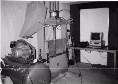
The testing apparatus, which is able to accommodate the model pipes inside a trench filled with a soil of uniform and predetermined density, consists of four main parts. These parts are: the loading system, the testing tank, the soil preparation device, and the data acquisition system. The general view of the testing apparatus together with all relevant attachments is shown in figure 1. A brief description of each part follows.
The Loading System
The loading system consists of the loading frame, the pneumatic cylinder, and the controlling unit. The loading frame comprises two stiff and heavy steel columns of 1443 mm height and a horizontal beam of 990 mm length, which supports the pneumatic cylinder. The position of the pneumatic cylinder, which has the internal diameter of 160 mm, can be changed horizontally along the beam by means of a simple gear system and a handle provided at one end of the beam to allow the load to be applied by any kind of eccentricity. The cylinder may produce monotonic or cyclic loads depending on the intensity of the input compressed air. The cyclic vertical loads with different amplitudes (up to 10 Kg/cm2), frequencies (up to 1 Hz), and number of load cycles can be produced and controlled by the cylinder. The controlling unit consists of an electro-mechanical valve, which can regulate the intensity of the compressed air required to producea cyclic load with the desired amplitude and frequency. It can also count the number of the applied cycles and stop the load generating process at the selected number of cycles.
The Testing Tank
The testing tank is a rigid steel box of 800×800×200 mm (800 mm length, 800 mm height and 200 mm width), which accommodates the soil and model pipe, and stands vertically along its square face while testing is in progress. The rigidity of the tank has been granted by using three stiff steel section of U-200 in the sides and bottom of the tank. The back face of the tank consists of rigid steel plate of 12mm in thickness, and its front face consists of a plexiglass of 20 mm in thickness supported by a strong solid brace of box section of 30x60 mm in dimensions. According to the preliminary tests, the measured deflection of the side faces of the tank proved to be negligible and in the ranges to satisfy the rigidity of the system. It is connected to the sides’ columns by means of two horizontal pivots, along which it can be rotated and fixed in the horizontal or vertical directions alternatively. Since in the special testing arrangement, the model pipe has to be set in its predetermined position prior to filling the tank, it must have the ability of being set horizontally during the preparation stage. After completing the preparation and before applying the load, the tank is set in the vertical position by rotating it 90 degrees quite gently. To allow the visual observations of the sand-pipe system as well as the photo scanning, the front face of the tank is made of a plexiglass, which can be removed during the preparation stage.Seven circular holes of 50 mm in diameter have been provided in the back face of the tank to accommodate the displacement transducers at any required point, at which the model pipe may be set. Also 9 square holes of 40 mm in dimensions have been provided for placing the contact pressure transducers. Seven of these holes are located on the base and the two others on the sides of the testing tank.
The Soil Preparation Device
The method used to deposit the soil in the testing tank at a known and uniform density was based on the one developed by Koulbuzewski [6] which is known as the raining technique. A moveable steel tank of 300x300x450mm (300 mm length, 300 mm width and 450 mm height), ending into an inclined funnel system outlet was mounted above the testing tank, and used as a hopper to pour the testing material from different heights. A simple sliding system of a perforated plate was provided in the outlet of the funnel to start or stop raining the soil. Different perforated plates could be used to change the flow of raining.
Before using the hopper for depositing the soil in the tank, the raining device was calibrated using different heights of pouring and different perforated plates. Consequently, the required height of pouring and perforated plate to get the desired density could be selected for a special test. Prior to start raining, the testing tank was set to the horizontal position and the model pipe was placed at the desired point. The embedment depth of the pipe was adjusted by limiting the top of the tank by means of a temporary wooden wall. Then the free end of the pipe was sealed and the soil was poured to the tank. The surface of the soil was then leveled and the plexiglass was placed and fixed. The testing tank was rotated to the vertical position quite gently. At this stage the loading plate (a steel plate of 200x100x20 mm) was placed on the surface of the soil at the desired position and the system was ready to be tested under different loading conditions.
The Data Acquisition System and Instruments
A special data acquisition system was developed by which all stresses and strains could be read and recorded automatically. The system was able to read the data from sixty channels simultaneously. Three contact pressure transducers were used to scan the normal and shear stresses on the base and sides of the soil trench. A special displacement transducer was developed to detect the radial deflections of the model pipes. It had eight spring steel arms, which could be in touch with eight points on the circumference of the tested pipe and scan any changes in its radius at the relevant points, while the test was in progress. A cylindrical load cell was also placed in the loading shaft to detect the pattern of the applied loads on the trench surface accurately.3. THE TESTING MATERIALS
silica sand of grains size between 0.38 and 1.04 mm, with D50 = 0.75 mm, Cc = 1.01, Cu = 1.32 and Gs =
2.67. The maximum and minimum porosities of this sand, measured by the raining method were 50% and 40% respectively. In order to study the effect of the soil density on the behavior of the buried pipe, three different relative densities: 48.5%, 66.5%, and 85% were selected as the relative loose, medium dense and densest states, respectively. The pipes used in this research had 100 mm diameter and 200 mm length. These pipes were made of thin steel plates of 0.4 mm thick by point welding at its two edges overlapped some 8 mm. The modulus of elasticity, the Poissons’ ratio and the yield strength of the used steel were 2.1×10E6 (Kg/cm2), 0.3 and 2400 (Kg/cm2) respectively. In order to prevent entering sand particles inside the pipe when it was embedded in the trench, the two ends of the so built pipe were stuck by strip foam before placing it in the tank.
4. THE TESTING PROGRAM
Sixty tests in different series were planned and carried out in this research. The first 10 tests were repeated carefully to examine the performance of the apparatus, the accuracy of the measurements, and the repeatability of the system that proved to be quite satisfactory. The next 50 tests were scheduled for performance in each series as follows:
a) 24 tests in the densest state (RD=85%) under different cyclic loads with different eccentricities and for four embedment depths of 1D, 1.25D, 1.5D, and 2D, in which the D was the pipe diameter.
b) 16 tests in the medium dense state (RD=66.5%) under different cyclic loads with different eccentricities and for three embedment depths of 1D, 1.25D, and1.5D.
c) 10 tests in the relatively loose state (RD = 48.5%) under different cyclic loads with different eccentricities and for three embedment depths of 1D, 1.5D, and 2D.
5. RESULTS
The failure mechanism of the soil-pipe system was
found to be a function of the pipe embedment depth, the soil relative density, and the cyclic loads eccentricity and amplitude. While in main tests performed on the buried pipes in weakly compacted sand, (relative loose state), the failure of the pipe usually was accompanied by the failure of the loading plate (foundation), the pipe in dense sand with sufficient embedment depth, mostly remained undamaged at the time of the failure which happened due to excessive settlement of the loading plate, even under large cyclic loads. The other factor associated with the general behavior of the buried pipes under cyclic loads, is the large portion of the deflection of the pipe at the end of the first pulse compared with its total displacement due to a number of load cycles. It may be attributed to the impact effect of the first pulse leading to a large plastic strain of the surrounding soils. The detailed results of the tests and discussion about them are presented in following sections.
The Role of the Soil Density
The entire cross sections of the tested pipes before and after application of the cyclic loads for three selected densities are shown in figure 2. In these tests the cyclic loads were applied on the centerline of the pipes by amplitude of 0.4 (Kg/cm2) and frequency of 0.3 Hz, and the pipes were placed at a depth of 1D for all series.As can be seen from the figure, the maximum deflection occurred at the crown of the pipe for all three cases. This vertical deflection causes, by a lesser amount, considerable horizontal deflections at both sides of the pipe. For all cases, the induced deflections in the first cycle are remarkably larger than those in the next cycles. The key role of the soil density in the deformational behavior of the pipe is quite evident. While the maximum vertical deflection of the pipe in dense soil in the first cycle is 3.639 mm, it increases to some 60% in the medium dense (5.851 mm), and even to more than 110% in case of relatively loose soil (7.90 mm). The effect of the soil density on the behavior of buried pipes can also be seen in Figure 3. It can be observed that when the soil is relatively loose, the impact of the load cycles becomes less important.
Figure 2. The radial deflections of the tested pipes under central cyclic loads.
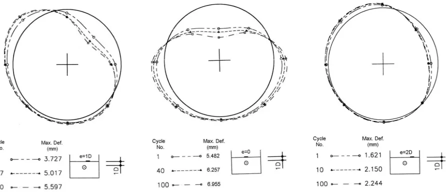
radial deflections of buried pipes under eccentric cyclic loads are shown in figure 4. In these tests the cyclic loads by amplitude of 0.6 (Kg/cm2) were applied eccentrically on the top of the soil trench inside which the tested pipe was buried at a depth of 1D. The soil was prepared in the dense state and the load was applied at 1D and 2D out of pipes’ centerline. As can be seen from the figure, the position of the point with a maximum radial deflection shifted towards the right side of the pipe, in the direction of existing eccentricity. The value of the maximum deflection in case of 1D eccentricity at the end of the first cycle is 3.727 mm. When the load eccentricity was increased to 2D; the maximum deflection was reduced more than 55%. The variations of the maximum deflections versus values of the load eccentricities under
different load cycles are also shown in Figure 5. It can be seen that the impact of the loads for eccentricity of more than 2.5D becomes almost negligible, while the reduction effect of the eccentricity on the pipe behavior at different cycles is nearly the same. Finally, it can be concluded that the minimum required failure load happen when the cyclic load is applied over the pipe centerline.
The Effect of the Embedment Depth
The variations of the maximum deflections of the buried pipes inside the dense soil versus different depths of embedment under cyclic loads by amplitude of 0.5 (Kg/cm2), are plotted in figure 6. The cyclic loads in these tests were applied on the centerline of the pipes. It can be seen that an increase in the embedment depth of the pipe in theDr=85%
Dr=66.5%
ranges of 1D to 1.5D results in a sharp decrease in the maximum deflections of the pipe while increasing the depth more than 1.5D cannot affect the behavior of the pipe considerably. This is true and almost the same for different numbers of the load cycles.
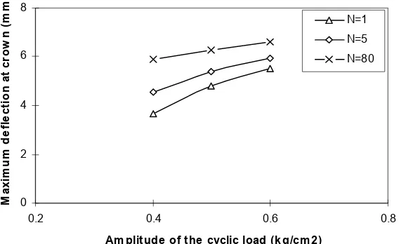
The Effect of the Amplitude of the Cyclic
Load
The influence of the amplitude of the cyclic loads on the maximum deflections of the buried pipes is shown in figure 7. As expected, theincrease in the amplitude of the cyclic loads directly causes the maximum deflections of the buried pipes to increase. Alternatively it can be seen from the graphs that the pipe under a cyclic load with low amplitude may have the same deflection under a cyclic load with high amplitude, provided that the cycles of the load continue for a long period. Consequently, the strong earthquakes with a very short duration may cause the same damage to the buried pipes as weaker earthquakes, but with a longer duration.
2 4 6 8 10
40 60 80 100
Relative density,Dr(%)
M
a
x
im
u
m
de
fl
e
c
ti
on a
t
c
row
n(
m
m
N=1 N=5 N=20
Figure 3. Variations of the maximum deflections of pipes buried at 1D depth, versus soil relative density, under central cyclic loads with amplitude of 0.4 (Kg/cm2).
0 1 2 3 4 5 6 7
0 1 2 3
Ecce ntricity of the applie d load(in te rm s of pipe diam e te r,D)
M
a
x
im
u
m
d
e
fl
e
c
ti
on
(m
m
)
N= 1 N=5 N=50
Figure 5. Variation of the maximum deflections of pipes buried in the dense sand at 1D depth, versus load eccentricity, under cyclic loads with amplitude of 0.6 (Kg/cm2).
0 2 4 6 8
0.75 1 1.25 1.5 1.75
De pth of e m be dm e nt(in te r m s of pipe diam e te r,D)
M
ax
im
u
m
d
e
fl
e
c
ti
o
n
at
c
ro
w
n
(m
m
)
N=1 N=5 N=100
Figure 6. Variations of the maximum deflections of pipes buried in the dense sand, versus depth of embedment, under central cyclic loads with amplitude of 0.5 (Kg/cm2).
0 2 4 6 8
0.2 0.4 0.6 0.8
Am plitude of the cyclic load(k g/cm 2)
M
ax
im
u
m
d
e
fl
e
c
ti
o
n
at
c
ro
w
n
(m
m
)
N=1 N=5 N=80
6. SUMMARY AND CONCLUSIONS
To study the behavior of buried pipes under cyclic loading conditions experimentally, a physical model was developed in Amirkabir University of Technology. The steel flexible model pipes were placed inside a soil trench of medium silica sand. The trench was prepared by raining technique at three different relative densities inside the testing tank. The depth of the pipes in the trench was changed and the cyclic loads with different amplitudes were applied on the trench surface centrally and eccentrically.
Some 60 tests were carried out and the main factors affecting the soil-pipe interaction were investigated. The deflection behavior and the failure mechanism of the system highly depend on the soil density, embedment depth, load’s amplitude, and load’s eccentricity. The failure of the soil-pipe system in dense soils for embedment depth below 1.5D happened due to large deflections of the pipe and loading plate together. For embedment depths between 1.5D and 2D it happened due to excessive settlements of the loading plate, which caused minor damages to the pipe. Finally for embedment depths of more than 2D, even under high cyclic loads in the tested range, the failure happened only due to excessive settlements of the loading plate without causing considerable damage to the pipe. However, in relatively loose soils, due to weak contacts and poor interlocking of the grains and special arrangements of the soil fabrics, regardless of the embedment depth, even under low cyclic loads, the failure of the system usually occurred in the first cycles due to local buckling or large
deflection of the pipe together with excessive settlement of the loading plate.
Thus, leaving the soils surrounding buried pipes uncompacted may result in serious damages to pipes during earthquake loadings. The above-mentioned depth (equal 2D) can be recommended as the minimum required depths for safe design and performance of buried pipes in dense soils.
7. REFERENCES
1. Shimamara, K., et al., “Loads on Pipes Buried in a Non-Liquefaction Layer Due to Non-Liquefaction -Induced Ground Displacement”, Proc. of the 12th World Conf. on Earthquake
Eng., Rocketbyte Information System: Aucland, New Zealand, (2000), 492-499.
2. Rashidov, T., “Vulnerability of Lifelines System in the Tashkent City and Ways of Reduction of Damage”,
Abs. Vol. of the 9th Int. Conf. on Soil Dynamics and
Earthquake Engineering, SDEE99, Eds. K. Atakan and L. Ottemoller, Elsevier: Norway, (1999), 164-170. 3. Mohri, Y., Kawabata, T., and Ling, H. I., “Experimental
Study on the Effects of Vertical Shaking on the Behavior of Underground Pipelines”, Proc. of the 2nd Int. Conf. on
Earthquake Geotechnical Engineering, Ed. Pedro. S. Seco e Pinto, Balkema: Retterdom, (1999), 489-494. 4. Bueno, B. D. S., “The Behavior of Thin Walled Pipes in
Trenches”, Ph.D. Thesis, Civil Eng. Dept., Leeds University, UK, (1987).
5. Mir Mohammad Hosseini, S. M. and Moghaddas Tafreshi, S. N., “A New Physical Model to Study the Behavior of Buried Pipes Under Cyclic Loading Condition”, Proc. of the 12th World Conf. on Earthquake
Eng., Rocketbyte Information System: Auckland New Zealand, P. No. 0889, (2000), 889-896.