Vol.9 (2019) No. 1
ISSN: 2088-5334
Analysis of Image Transmission using MIMO-Alamouti Space-Time
Encoding
Manpreet Kaur
#1, Lavish Kansal
#2, Navjot Kaur
#3, Gurjot Singh Gaba
#4, Dharma P. Agrawal
* #School of Electronics and Electrical Engineering, Lovely Professional University, Punjab, India - 144402 E-mail:[email protected]; [email protected]; [email protected];[email protected],
*
Department of Electrical Engineering and Computing Systems, University of Cincinnati, Ohio, USA - 45221 E-mail: [email protected]
Abstract
—
Rapid increase in requirements of high speed transmission of multi-media information resulted in development of MIMO systems. MIMO systems have emerged as the most efficient methodology for the high speed robust data transmission. In this paper, the performance of Alamouti Space-time block coded MIMO system is analysed using the metric of efficient image transmission over the Rayleigh fading channel. The transmitted image is modulated using M-PSK modulation technique, and its reconstructed version is plotted as an output function. Zero-forcing equalization is done for the detection of the original symbols from the received symbols which are influenced by the multipath fading and the channel noise. The results for image transmission using 2×1 and 2×2 Alamouti STBC are evaluated for different SNR values. The inverse relationship between the SNR and BER in the results depict that the high value of SNR and receiver antenna leads to enhanced system efficiency with reduced BER and distortion less recovery of image. It is very evident from the analysis of the received images that as we increase the SNR or the number of the antennas at the receiving side, the quality of the received image improves for the same channel environment. During the analysis, it is also found that increasing the number of bits forming one symbol in M-PSK modulation increase the BER which is undesirable. Thus, trade-off between the number of antenna, SNR and the M value of PSK is an essential requirement for achieving enhanced performance.Keywords
—
MIMO; M-PSK; alamouti; image communication; Rayleigh; BER.I.INTRODUCTION
MIMO system is the system used in the wireless communication area, which comprises various input and output antennas at the sender and receiver side respectively [1]-[10]. The new era in the wireless communication is opened by utilizing the various antennas on the sender and receiver side to make the communication reliable which in results enhance the system efficiency. The main MIMO’s idea is the improvement in the quality of the system by employing the connection and combination of various sender and receiver antennas [11]-[14]. Due to the reason of excessive growth in the capacity offered by MIMO system, offer, this system achieves a lot of interest in the area of mobile communication. The primary issue of the wireless channel is the different routes followed by the signal that results in the fading [2], [15], [16]. MIMO methodology can be implemented diverse forms, i.e. spatial diversity, spatial multiplexing, and beamforming where each of the forms has its own merits and demerits. The adverse effects of the
maximum data rates. However, all the three MIMO methodologies have their trade-offs for various applications. Space-time trellis coding [3] is one of the other coding method used for the MIMO system, which has a similar idea to that of convolutional coding. It consists of a trellis structure, and it depicts the data to be transmitted through various antennas. One of its advantages is the coding benefit achieved but only at the cost of complexity of decoding. Particular space-time trellis codes that work very well in the slow fading environment are generated for 2 to 4 sender antennas [14]-[16]. Space-time trellis code generated for two sender antennas is more complicated than the Alamouti scheme for two sender antennas, but its performance is better than the Alamouti scheme.
A. MIMO-Alamouti Encoding
MIMO makes use of spatial dimension and multipath to improve wireless system capacity, range, reliability, and efficiency. There are various ways for implementation of MIMO through which capacity and diversity gain can be achieved and can combat certain multipath fading effects. It makes use of spatial dimension and multipath to improve wireless system capacity, range, reliability, and efficiency. There can be much of MIMO configurations like 2x2 MIMO where two antennas are used to transmit the signal, and two antennas are used to receive and similarly, 4x4 and 8x8 MIMO configurations are used for achieving high data rates and high-frequency efficiency. There can be much of MIMO configurations like 2*2 MIMO where two antennas are used to transmit the signal, and two antennas are used to receive.
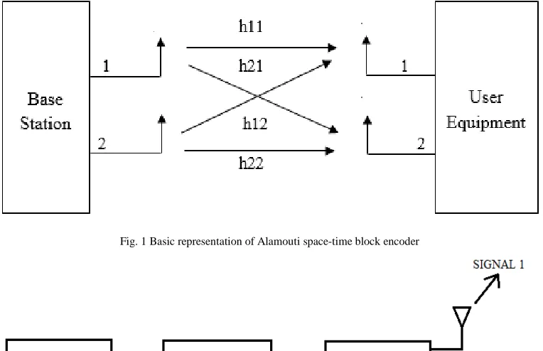
Here multiple antennas are used to send multiple parallel signals as shown in Figure 1. Firstly, beamforming is performed to maintain the beam on the side so that eye on the particular signal can be retained excluding other signals. Same data to transmitter and receiver is being sent so that they can experience different fading is popularly known as spatial diversity.
In the Alamouti scheme, two signal will be transmitted at a time by employing the two-branch spatial-transmit diversity methodology. The symbols to be transmitted are grouped so that the same can be transmitted during two consecutive time intervals. A basic block diagram of the Alamouti spatial-transmit diversity methodology is depicted in Figure 2. The basic idea of Alamouti spatial-transmit diversity methodology is the use of spatial dimensions through the use of space-time processing (STP). Symbol mapping and the space-time encoding is also done at the transmitter side, and the receiver side the symbol demapping, and the decoding will be performed. Parallel transmissions are carried out through both the transmitting antennas to fulfill the need of STP [11]. These codes allow a simple ML decoding at the receiver [7]. There is no need of a closed loop between the transmitter and receiver. The computational complexity of the Alamouti transmits diversity scheme is similar to the maximum ratio receive combining (MRRC) [6]. Power is equally divided among two transmit antennas.
Fig. 1 Basic representation of Alamouti space-time block encoder
Let and are the symbols as the input to the encoder. Then Space-time Encoder encodes the information symbols and gives it to two transmit antennas in the following form:
= − ∗ ∗ (1)
During the first time slot, the first antenna transmits
and sthe econd antenna transmits . during sea cond
time slot, fithe rst antenna transmits negative of cothe mplex conjugate of sya mbol transmitted during fithe rst time slot
from sethe cond antenna i.e.− ∗ and secthe ond antenna
transmits complex conjugate of i.e. ∗.
The two columns in the (1) equation are orthogonal to each other, so the dot product of these two vectors is equal to zero. The fading coefficients from first transmit antenna to
receive antenna is ℎ ( ) and fthe ading coefficient from
second transmit antenna to receive antenna is ℎ ( ). So the
received signal at the receiver can be represented in the following format:
= ℎ + ℎ + (2)
= −ℎ ∗+ ℎ ∗+ (3)
Where and are the AWGN components with zero mean
and unit variance added at the time slots and +
respectively.
It is analyzed that the BER of the Alamouti scheme equals the BER of Maximal Ratio Combining (MRC). Utilization of two antennas results in the twice of MRC’s transmitted power. i.e., BER performance of 2×1 case of Alamouti is 3 dB poorer than 1×2 case of MRC [4]. In the methodology mentioned above, the channel encoding is not being utilized as the incorporation of the channel encoding will make the system more complex and also results in wastage of resources due to added redundancy.
III.MATERIAL AND METHOD
The communication of an image from transmitter end to receiver end, over any propagation medium, is known as image transmission. Generating an efficient communication of an image instead of the voice signal over a medium is the requirement for a mobile radio link. There is a requirement of the compatibility of an image with the characteristics of a channel like bandwidth for this transmission purpose [16]. Large bandwidth is needed for the image communication. Large information is required for the representation of an image which leads data at high rates, and hence, results in a distorted image. To recover the distortionless image at the receiving side, the transmission can be done using various techniques. The whole procedure of transmission of an image and retrieving it back at the receiver end discussed. Figure 3 presents the detailed procedure followed for the transmission of an image. In the methodology mentioned above, the channel encoding is not being utilized as the incorporation of the channel encoding will make the system more complex and also results in wastage of resources due to added redundancy. An image is modulated using MPSK modulation levels followed by encoding by employing Alamouti encoding scheme for transmission over a Rayleigh
fading channel, which does not follow the direct path, i.e., no any line of sight. Now at the receiver end, Zero-forcing equalizer is used followed by the demodulation using MPSK demodulator for recovery of a transmitted image, i.e., the recovery procedure of a transmitted image is done using the inverse procedure of transmission. Hence, the BER analysis is done for the transmission and reception of an image using different values of M [5], [8], [13].
Fig. 3 Flowchart of image transmission using MIMO-Alamouti coding
IV.RESULTS AND DISCUSSION
Here, BER performance for M-PSK using Alamouti MIMO channel model with diverse antenna configurations over Rayleigh channel is evaluated. The employment of Zero-forcing equalizer is done for the detection, and different modulation levels are used for the modulation process for all possible antenna architectures of Alamouti. The transmitted image is modulated using the M-PSK modulation technique, and its reconstructed version is plotted as an output function showing the inverse relationship between the SNR values and BER values.
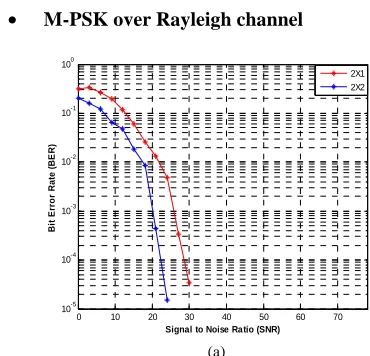
• M-PSK over Rayleigh channel
(a)
0 10 20 30 40 50 60 70 10-5 10-4 10-3 10-2 10-1 100
Signal to Noise Ratio (SNR)
(b) (c)
(d)
Fig. 4: SNR vs. BER plots for M-PSK using Alamouti MIMO channel model with diverse antenna configurations over Rayleigh channel a) 8-PSK b) 16-PSK c) 32-PSK d) 64-PSK
The representation of SNR vs. BER plot of MIMO system for image transmission with MPSK modulation over Rayleigh channel for all antenna architectures using Alamouti MIMO channel model with zero forcing detectors is given in Figure 4. The analysis done from the graph is that BER decreases with the increment in the number of receiver antennas and it happens because of space diversity. Also, it is analyzed that the higher value of SNR results in the improved system efficiency.
For different values of modulation levels, the different SNR values using Alamouti MIMO channel model with diverse antenna configurations are represented in Table 1. It is depicted that for 8-PSK, the SNR value decreases from 28 dB to 23 dB by increasing antennas from 1 to 2. Similarly, the SNR value decreases from 36 dB to 30 dB by increasing antennas from 1 to 2 for 16-PSK, 54 dB to 42 dB for 32-PSK, and 64 dB to 57 dB for 64-PSK. Therefore, it is analyzed that with the increment in the antennas at the
receiver side from 1 to 2, the SNR improvement in the range of 5 dB to 12 dB is there for the same value of BER. The image transferred is shown in Figure 5. 2×2 Alamouti STBC encoder is used for the transmission. Modulation performed is M-PSK technique done before encoding. The system performance is examined with the plot of SNR and BER values achieved.
TABLEI
SNR VALUES FOR VARIOUS M VALUES USING ALAMOUTI SPACE-TIME CODING OVER RAYLEIGH CHANNEL
Number of Receiver Antennas
SNR values for different values of M in M-PSK (in dB)
8-PSK 16-PSK 32-PSK 64-PSK
1 28 36 54 64
2 23 30 42 57
0 10 20 30 40 50 60 70
10-5 10-4 10-3 10-2 10-1 100
Signal to Noise Ratio (SNR)
B it E rr o r R a te ( B E R ) 2X1 2X2
0 10 20 30 40 50 60 70
10-4 10-3 10-2 10-1 100
Signal to Noise Ratio (SNR)
B it E rr o r R a te ( B E R ) 2X1 2X2
0 10 20 30 40 50 60 70
10-5 10-4 10-3 10-2 10-1 100
Signal to Noise Ratio (SNR)
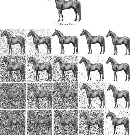
Fig. 5: Original Image
Fig. 6 Image received for M-PSK using Alamouti Space-Time Coding with 1 receiver antenna at different SNR values (Column-wise: 0dB, 10dB, 20dB, 30dB and 40dB) for diverse modulation levels (Row-wise: 8-PSK, 16-PSK, 32-PSK and 64-PSK)
The reconstructed images at the receiver side using Alamouti Space-time block code with receiver 1 for M-PSK modulation is presented in Figure 6. The images are received considering 0 dB to 40 dB as SNR values with a difference of 10 dB for the M-PSK (8-PSK to 64-PSK) modulation levels. The SNR values are increased column-wise, whereas the values of modulation levels are increased row-wise. It is
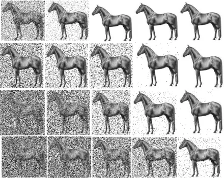
Fig.7 Image received for M-PSK using Alamouti Space-Time Coding with 2 receiver antenna at different SNR values (Column-wise: 0dB, 10dB, 20dB, 30dB and 40dB) for diverse modulation levels (Row-wise: 8-PSK, 16-PSK, 32-PSK and 64-PSK)
The reconstructed images at the receiver side using Alamouti Space-time block code with receiver 2 for M-PSK modulation is presented in Figure 7. The images are received considering 0 dB to 40 dB as SNR values with a difference of 10 dB for the M-PSK (8-PSK to 64-PSK) modulation levels. The SNR values are increased column-wise, whereas the values of modulation levels are increased row-wise. It is depicted from the figure that for 8-PSK modulation level, the BER for image retrieved at 0 dB is more than the BER at 10dB, 20dB, 30dB, and 40dB, i.e., BER decreases with the increase in SNR value, and image becomes more clear but as we go from 8-PSK to 64-PSK, i.e., with the increase in the M value, the BER increases. On comparing figure 7 with figure 6, it is also analyzed that, with the increase in the number of antennas, the BER also decreases and the image retrieved using two receiver antennas are brighter than the image retrieved using one receiver antenna.
IV.CONCLUSION
This paper discusses the performance analysis using Alamouti MIMO channel model with diverse antenna configurations for M-PSK modulation over Rayleigh channel by employing the Alamouti scheme. The images are received by taking 0 dB to 40 dB as SNR values (with a difference of 10 dB) for the 8-PSK to 64-PSK modulation levels. The analysis disclosed that BER decreases with the
increment in the number of receiver antennas and it happens because of space diversity. Also, it is analyzed that the higher value of SNR results in the improved system efficiency. However, with the increase in the modulation levels, the BER increases because of increase in the number of constellation points. Hence, the image retrieved using two receiver antennas is clearer than the image retrieved using one receiver antenna having less BER value. In future, the proposed methodology can be extended for more significant number of transmitting and receiving antennas, i.e. Massive MIMO systems. Moreover, OFDM methodology can also be incorporated with MIMO for the transmission of multimedia information.
REFERENCES
[1] S. Alamouti, “A simple transmit diversity technique for wireless communications,” IEEE Journal on Selected Areas Communication, Vol. 16, Issue 8, pp. 1451-1458, 1998.
[2] N. R. Deepak & S. Balaji, “Performance analysis of MIMO-based Transmission techniques for image quality in a 4G wireless network”, IEEE International Conference on Computational Intelligence and Computing Research, pp. 1-5, 2015.
[3] G. Ganesan & P. Stoic, “Space-time block codes: a maximum SNR approach,” IEEE Transactions on Information Theory, Vol. 47, Issue 4, pp. 1650–1656, 2001.
[5] H. Kasban & M. A. M. M. K. El-Bendary, “Performance Improvement of Digital Image Transmission over Mobile WiMAX Networks,” Wireless Personal Communication, Vol. 94, Issue 3, pp. 1087-1103, 2017
[6] T. H. Liu, “Analysis of Alamouti STBC MIMO system with spatial division multiplexing over Rayleigh fading channel,” IEEE Transactions on Wireless Communications, Vol. 14, Issue 9, pp. 5156-5170, 2015.
[7] A. Lozano, “Transmit Diversity vs. Spatial Multiplexing in modern MIMO systems,” IEEE Transactions on Wireless Communications, Vol. 9, Issue 1, pp. 186-197, 2010.
[8] B. P. Prlincevic & P. C. Spalevic, “Performances of the image transmission over FSO channel in last mile connection,” IEEE Telecommunications Forum, pp. 1-7, 2016.
[9] V. Tarokh, H. Jafarkhani & A. R. Calderbank, “Space-time block codes from orthogonal designs,” IEEE Transactions Information Theory, Vol. 45, Issue 5, pp. 1456-1467, 1999.
[10] V. Tarokh, A. Naguib, N. Seshadri & A. R. Calderbank, “Combined array processing and space-time coding,” IEEE Transactions Information Theory, Vol. 45, Issue 4, pp. 1121-1128, 1999. [11] V. Tarokh, N. Seshadri & A. R. Calderbank, “Space-time codes for
high data rate wireless communication: Performance analysis and
code construction,” IEEE Transactions Information Theory, Vol. 44, Issue 2, pp. 744–765, 1999.
[12] K. Tashiro, L. Jr. Lanante, M. Kurosaki & H. Ochi, “High-resolution Image Transmission over MIMO-OFDM E-SDM System with JSCC,” IEEE International Conference on Consumer Electronics, pp. 379-383, 2014.
[13] Y. Zhuang, N. Jiang, Q. Li, D. K. W. Chiu & H. Hu, “Personalized and efficient social image transmission scheme in mobile wireless network” Multimedia Tools Applications, Vol. 75, Issue 6, pp. 2931-2968, 2016.
[14] M. Lordo, S. Greedy, A. Vukovic, C. Smart & D. W. P. Thomas, “Image transmission using OSTBC encoded 16-QAM over MIMO time-selective fading channels”, Loughborough Antennas & Propagation Conference, pp. 1-5, 2017.
[15] R. Negi & K. Sharma, “Image Transmission in OSTBC MIMO-PLC over Nakagami-m Distributed Background Noise,” In Proceedings of International Congress on Information and Communication Technology, pp. 513-523, 2016.