87
Copyright © 2016. Vandana Publications. All Rights Reserved.
Volume-6, Issue-6, November-December 2016
International Journal of Engineering and Management Research
Page Number: 87-94
ATM SWITCH: As an Application of VLSI in Telecommunication System
Shubh Prakash1, Amita Verma2
1M.Tech Student, Electronics and Communication Engineering Department, Maharishi University of Information Technology, Lucknow , Uttar Pradesh, INDIA
2
Assistant Professor, Electronics and Communication Engineering Department, Maharishi University of Information Technology, Lucknow , Uttar Pradesh, INDIA
ABSTRACT
Thus the paper proposes a new asynchronous transfer mode (ATM) switch architecture also known as barrel switch. It is made from n/2*n identical element switches which are kept around a cylindrical pattern and connected with each other.
The switch has following smart features
The switch architecture suites for high speed (<2.4 Gbps) cell switching.
It is non blocking and multistage self routing in nature.
The connections copied can be realized by the
switch.
For switch implementation, building block method is applicable thus full scalability is achieved. The cell loss rate and delay characteristic has been discussed by use of computer simulation result. Under random traffic, simulator result proves that 64*64 barrel switch has adequate cell loss rate and mean delay characteristics to an actual ATM switching system.
Key words: ATM; cell; ATM switch; copy con
I.
INTRODUCTION
An electronic switch is essentially just a switch that uses an electrical current, to turn on, usually turning off when the current is turned off. Some applications of switches can be quite inconvenient for someone to go and press a button to turn on or off, such as for the starter motor in a car, or the "turn off nuclear meltdown" button inside a nuclear reactor, or in an electronics project, a small low power device such as a receiver, must somehow power a large energy guzzling component, like the motor in a garage door opener. And others just want to control their houses with their computer's, which could never possible supply the 240v/120v mains needed to run some appliances.
To construct future B-ISDN systems, considerable research has been conducted. Asynchronous transfer mode (ATM) switches are one of the basic technologies of B-ISDN and much of the research has focused on constructing an ATM switch. ATM switches for 150 Mbps/600 Mbps cell switching have already been imple-mented [1, 2], and the interest of many researchers has turned to higher-speed ATM switches that would lead to
the development of a more flexible B-ISDN.
In this paper, an ATM switch architecture for high-speed switching called "barrel switch" is proposed and its characteristic is discussed. In section 2, the characteristics of this switch architecture to be satisfied for high-speed ATM switches is described. The barrel switch itself is proposed in section 3. Topology, two self-routing algorithms, the non blocking condition, and a building-block method also are discussed in this section. In section 4, the cell loss rate and the delay characteristics of this switch are discussed using computer simulation results.
II.
CHARACTERISTICS OF
HIGH-SPEED ATM SWITCHES
An architecture for a high-speed ATM switch must satisfy the following two criteria to alleviate bottlenecks in high-speed ATM switch implementation.
• Cell buffer criterion. Alleviating the speed limitations of RAM devices
88
Copyright © 2016. Vandana Publications. All Rights Reserved.
Such cell buffers generally are implemented using RAM devices, and these devices have access speed limitations. These speed limitations impose a limit on the throughput of cell buffers. Therefore, it is desirable that an ATM switch architecture for high-speed switching has the characteristic that the required throughput of RAMs, i.e., the required throughput of cell buffers, is as slow as possible.
• Cell switching algorithm criterion. Alleviating clock skew problems in ATM switches
There are some cell switching algorithms for ATM switches which require that cells are input through all input ports at the same time and that all element switches operate synchronously (e.g., the Batcher sorting network [3]). In this type of algorithm, it is assumed that system clock for the ATM switch can be distributed to cell buffers located on all the input ports and to every element switch with no clock skew. Unfortunately, clock distribution with zero skew is impractical and clock skew limits the maximum bit rate for this type of ATM switch. By contrast, in other cell switching algorithms, the element switches do not need to operate synchronously (e.g., the buffered Banyan network [4]). Cell buffers on the element switches can be used as elastic stores in this type of architecture, and the clock skew problem is avoided. The latter type of algorithm is more suitable than the former for high-speed cell switching.
An ATM switch architecture which satisfies the fore mentioned criteria is considered suitable for high-speed switching because such architecture can operate at higher speed than that architecture which does not satisfy such criteria.
The buffered Banyan network is one architecture which satisfies the two fore mentioned criteria. Thus, the author has been discussing the possibility of an ATM switch using the buffered Banyan network [5, 6]. However,
the buffered Banyan network has the following three disadvantages:
1. The buffered Banyan network is a blocking network at connection level. Therefore, a connection setup procedure must manage the total bit rate for all connections on each internal link. This adds no negligible overhead to the connection set-up procedure, especially in the case of a large ATM switch.
1 Interconnections between stages form a perfect shuffle [7], thus the interconnection pattern becomes more complex when the switch size is increased. This makes it difficult to adopt a building-block method in constructing an ATM switch system.
2 Copy connections cannot be realized using the buffered Banyan network only. An additional component, such as the copy network in [8], must be added to the buffered Banyan network.
In this paper, an ATM switch which satisfies the two fore mentioned criteria while also overcoming the three foregoing disadvantages of the buffered Banyan network is proposed.
III.
BARREL SWITCH
3.1. Barrel switch topology
The barrel switch is an ATM switch architecture designed to satisfy the five requirements given in the foregoing. The topology of the switch is shown in Fig. 1. This figure shows a barrel switch which has eight input ports and eight output ports. The barrel switch is constructed from n stages, each of which has «/2 element switches with two inlets and two outlets. Here, n is the switch size. These element switches are laid out around a cylinder and connected to each other by internal links following the rule described below. This shape gives the 12 "barrel switch' its name. Each input port or output port is given a number as shown in this figure. Each stage also is g}\ea a stage number as shown in this figure.
The interconnections between stages of the barrel
switch are now defined. In this definition, the inlet of each element switch at each stage is given a number, i.e., /(O), /(I), -, /(/i-l), in order from top to bottom in Fig. 1, matching the input/output port numbers. In the same manner, the outlet of each element switch is given a number, i.e., 0(0), 0(1), , O{n-l).
Using these inlet/outlet numbers, the interconnec-tions between stages can be defmed as follows.
• Connection between an outlet in stage i x 2-1 and an inlet in stage / X 2
—Connect from an outlet 0(7) to an inlet /((/ + 1) modn).
• Connection between an outlet in stage k x 2 and an inlet in stage A: x 2 -*-1
—Connect from an outlet 0((/ + 1) mod n) to an inlet /(/).
(Here, 1 < i < n/2, 0 < j < n -I, I < k < n/21.)
3.2 Self-routing algorithm for the barrel switch 3.2.1 outing tags for the barrel switch
89
Copyright © 2016. Vandana Publications. All Rights Reserved.
A routing tag is used for this routing in each element switch.
The self-routing algorithm for the barrel switch is a form of Input-to-Output address difference routing [9]. Each cell input has a "difference number" as the routing tag. The difference numbers for the barrel switch are defined as follows.
It is assumed that the number of the output ports carrying the output from the cell is A and the number of the input port carrying input to the cell is B.
For input from an input port which has an event number:
—A - 5 - 1; if negative, add n.
For input from an input p)ort which has an odd number
—B - i4 + 1; if negative, add n; if this result equals n, set to 0.
Note that this difference number would be simpler in a version of the barrel switch with n -I stages [10]. However, the n-stage barrel switch is considered in this paper since this version can be constructed using the building-block method described later. Also, it should be noted that the difference numbers for cells from different input ports to the same output port are not the same, although routing tags to the same output port are identical in the buffered Banyan network. In an ATM switching system, however, this difference number is calculated only once at the connection set-up; thus, the calculation is not a heavy load on the connection set-up procedure.
3.2.2. Self-routing algorithm for point-to-point
connections
There are two versions of the self-routing algorithm for the barrel switch: one is for point-to-point connections only, and the other is for point-to-multipoint connections. The algorithm for point-to-point connections, called P-P routing, is described first.
The routing tag for input cells with P-P routing is the difference number. Each element switch determines the direction for each input cell according to the following
rules:
The difference number of an input cell is not zero.
—That cell is routed to cross dir. When the cell is output, the difference number is decreased by one.
• The difference number of an input cell is equal to zero.
—That cell is routed to straight dir.
(Here, cross_dir means that a cell from the upper inlet is routed to the lower outlet and vice versa; straightjdir
means that a cell from the upper inlet is routed to the upper outlet and vice versa.)
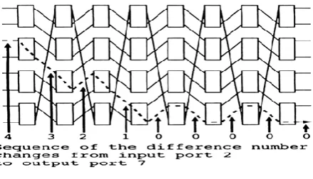
Figure 2 gives an example of cell switching using P-P routing. The sequence of difference number changes also is shown in this figure. Figure 2 also shows a route of a cell
which comes from the input port 2 and is destined to the output port 7. By the foregoing definition, the difference number of the cell when it comes in is 4. At the first stage, the difference number is not zero. Then an element switch outputs the cell to cross_dir. At the same time, the element switch decreases the difference number by one. At the following stage, the cell is output to the cross_dir while the difference number is not zero. After the difference number becomes zero, the cell is output to straight_dir.
By executing the foregoing operation at each ele-ment switch, the routing from any input port to any output port can be realized on the barrel switch.
3.2.3 Self-routing algorithm for point-to-multipoint connections
Next, the self-routing algorithm for point-to-multi-point connections, called COPY routing, is described.
90
Copyright © 2016. Vandana Publications. All Rights Reserved.
one is the stage number."
To set up a point-to-multipoint connection, the difference numbers corresponding to output ports to which copied cells should be routed are calculated. Then a bit related to each calculated difference number is set to one. Other bits not related to these difference numbers are set to zero. The routing end bit is set to zero when a cell enters the barrel switch.
Each element switch selects the direction of the input cells using the following rules.
• At each stage except the last
The routing end bit is zero. The input cell is routed to cross_dir. When this cell is output, the routing end bit of this cell is still zero. If a bit corresponding to the stage is one, a copied cell is made from the input cell and the copied cell is output to straight_dir. The routing end bit of the copied cell is rewritten to one.
The routing end bit is one. The input cell is routed to straight dir. The routing end bit of this cell is still one. • At the last stage
The routing end bit is zero. If a bit corresponding to the last stage is one, the input cell is routed to straight_dir. The routing end bit of this cell is rewritten to one. If that bit is zero, then the input cell is discarded.
The routing end bit is one. The input cell is routed to straight_dir. The routing end bit is still one.
In Fig. 4, an example of cell switching using COPY routing is shown. The dotted line shows the route for cells whose routing end bit is zero, and the dashed-dotted line shows the route for cells whose routing end
bit is one. In this figure, the route of a cell from the input port 2 to output ports 5 and 7 is shown. By the foregoing definition, the routing tag of the cell is "000101000" at the input port (here, the leftmost bit is the routing end bit).
At the first and second stages, the cell is output to cross_dir only because the corresponding bit in the routing tag is zero.
At the third stage, the cell is output to crossdir (the dotted line) and a copy cell is made to distend to straight dir (the dashed-dotted line) because the corresponding bit is one. The routing end bit of the copy cell is set to one.
At the following stages, the copy cell is routed to straight_dir and output to the desired output port 5.
The cell which is output to cross dir at the third stage is input to the element switch at the fourth stage and output to cross_dir. Then the cell is handled at the element switch in the fifth stage.
Because the corresponding bit in the routing tag is one, the element switch outputs the cell to cross dir and makes a copy cell to be destined to straight dir as in the third stage. At the following stages, the copy cell is routed to straight dir and output to the desired output port.
The cell which is output to cross_dir at the fifth stage is routed to cross dir at the following stages. At the last stage, this cell is discarded because the routing end bit of this cell is zero.
91
Copyright © 2016. Vandana Publications. All Rights Reserved.
3.2.4 Nonblocking condition for the barrel switchThe barrel switch has a function such that, if the bit rate for the internal links is set to twice that of the input/output ports, then this switch is nonblocking at the connection level, i.e., the total bit rate for all connections on an internal link does not exceed the capacity of the internal link.
In Fig. 5, cell paths for all input and output port pairs in P-P or COPY routing are shown. The dotted lines show paths for cells whose difference number is not zero or routing end bit is zero. The dashed-dotted lines show paths for cells whose difference number is zero or routing end bit is one. Solid circles show the points where a cell whose
difference number is zero is input to an element switch first or the routing end bit is rewritten from zero to one.
From this figure, it can be seen that a (virtual) crossbar switch is realized in a barrel switch if the solid circles are regarded as the crosspoints. Moreover, one input line (a dotted line) and one output line (a dashed-dotted line) of the crossbar switch are mapped onto one internal link of the barrel switch. Therefore, at any switch size, the barrel switch is nonblocking if the bit rate for the internal links is twice that of the input/output ports.
3.2.
3.2.5 High-speed cell switching with the barrel switch
The barrel switch has a suitable architecture for high-speed cell switching for two reasons.
First, the barrel switch is nonblocking if the bit rate of the internal links is doubled. Therefore, for example, if the element switches are identical input buffer switches and are implemented using the technique that can realize a 2.5 Gbps 8x 8 shared buffer ATM switch [11], the barrel switch constructed with these element switches can operate at 10 Gbps.
The second reason results from the forementioned routing algorithms. Each element switch in a barrel switch can decide on the direction of the input cells from the routing tag only. Both P-P routing and COPY routing have this feature. The cell buffers on the element switch are used as elastic stores; and some cell data signals, i.e., a bit clock for sampling the cell data signals and a signal showing the head of cells, are used in the cell transfer path between element switches; then the clock skew problem is alleviated. If this method is applied to the barrel switch, the clock phase in each portion need not be controlled.
By contrast, an ATM switch architecture in which the clock phase should be controlled is difficult to implement. Assuming that the speed is 10 Gbps per port and cells are handled in an 8-bit parallel form, the line length difference in the clock distribution circuit in the ATM switch should be less than about 2 cm to suppress the clock skew below quarter cycle (transmission speed of electrical signal = 15 cm/ns). The forementioned difficulty can be disregarded in the barrel switch.
It should be noted that the total amount of hardware should be reduced because the number of the element switch is large in the barrel switch. Reducing the length of the cell buffer is efficient in reducing the total hardware size. In this case, the backpressure (the flow control in [5]) can be applied to reduce the cell loss rate. It is assumed that the backpressure is as follows. The destination cell buffer, which receives a cell, outputs a signal called flow
control signal to show whether or not it can receive a cell. The source cell buffer, which outputs a cell to the destination cell buffer, refers the flow control signal at each cell output. If the destination cell buffer can receive a cell, the source cell buffer outputs a cell. The forementioned simple backpressure can be implemented at a high bit rate.
The barrel switch is nonblocking at the connection level because a virtual crossbar switch is in the barrel switch. The crosspoint buffer switch [12] is another architecture based on the crossbar switch.
The required throughput of cell buffers of this type is lower than that of the barrel switch. However, the barrel switch has the following advantage over the cross-point buffer switch.
92
Copyright © 2016. Vandana Publications. All Rights Reserved.
cells synchronized to one clock. To prevent the clock skew problem, an architecture based on cascade-connected elastic stores is proposed in [12]. However, this archi-tecture is disadvantageous in that the operation speed of the cell output control depends on the switch size, i.e., the cell output control is a bottleneck to implement a large-scale ATM switch. In the case of the barrel switch, this problem does not occur.
3.2.6 Building-block method to construct the barrel switch
The barrel switch has a topology which is easy to construct using a block method. One building-block method is described in Fig. 6.
This method uses a 2 x 2 module, as shown in Fig. 6(a). This module incorporates two element switches, i.e., one fixed internal link, three inputs, and three outputs. To form the topology of the barrel switch, these inputs and outputs are connected to other modules.
Figures 6(b) and (c) show 4x 4 and 8x 8 barrel switches using identical 2x 2 modules shown in Fig. 6(a), respectively. The 4x 4 switch is made from four 2x 2 modules, and the 8 x 8 switch consists of eight 2x 2 modules. In general, the n x n switch consists of tP/4 2x 2 modules.
As shown in these figures, interconnections between the stages of the barrel switch are almost the same for any switch size, whereas interconnections of the Banyan network are different if the switch size is varied. Thus, various switch sizes can be implemented by connecting identical modules. Moreover, the number of modules to which the outputs of each module are connected is fixed (there are only three) in any switch and module sizes and interconnections between stages are not intertwined.
Input Buffers Output Buffers (2 cells long) (32 cells long)
93
Copyright © 2016. Vandana Publications. All Rights Reserved.
IV.
BARREL SWITCH PERFORMANCE
EVALUATION
Computer simulations have been done with the
barrel switch, and the cell loss rate and delay characteris-tics were obtained from these simulations. The simulation results are given in this section.
4.1. Simulation model
The model used for these simulations is shown in Fig. 7. Input buffers are located on every input port of the
barrel switch. This buffer speeds up the bit rate from normal to double, and the buffers are two cells long; that
is, the buffer can hold two cells. Also, output buffers are located on every output port of the barrel switch. These buffers reduce the bit rate to normal and the buffers are 32 cells long. The backpressure discussed in section
3.2.5 is adopted from the output buffers through every element switch to the input buffers.
Each element switch is 2 X 2 the input buffer switch to keep the throughput of the cell buffers in the element switch low. The cell buffers in the element switch are four cells long. The offered load is random traffic, i.e., cells arrive with a Poisson distribution and the destinations for the arriving cells are selected randomly among all output ports with the same probability.
4.2. Performance comparison between P-P routing
and COPY routing
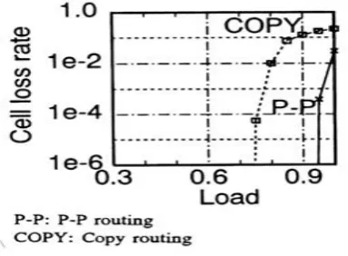
The cell loss rate of 8 x 8 barrel switch is shown in Fig. 8. The X-axis is the offered load and the F-axis is the cell loss rate.
In this figure, the performance of P-P and COPY routing is shown by curves marked "P-P" and "COPY," respectively. Note that only point-to-point connections are made with COPY routing in these simulations. In case of COPY routing, input cells are always transferred to the last stage and some copy cells are made at desired points. A point-to-point connection places a heavier load 18 COPY: Copy routing
on the barrel switch than a point-to-multipoint connection if the total bit rates for all connections on all input and output ports do not exceed the capacity of the input and output ports. If a point-to-multipoint connection is set up instead of a point-to-point connection, the load of some input ports and some internal links decreases. Therefore, considering point-to-point connections only gives a worst
case scenario for COPY routing.
Figure 8 shows that the cell loss rate for P-P routing is acceptable for an ATM switching system, whereas that for COPY routing is not so good. Following COPY routing and the simulation model, input load on the last stage for COPY routing is two times as heavy as that for P-P routing due to these copied cells. Input load on other stages for COPY routing also is heavier than that for P-P routing. The cell losses in this model are due mainly to the cell buffers of the element switches located near the input ports that become full. This may occur frequently under the conditions in which the barrel switch load is heavy which is why the cell loss rate for COPY routing is worse than that for P-P routing.
94
Copyright © 2016. Vandana Publications. All Rights Reserved.
4.3 Improvement of COPY routing performance
The COPY routing performance can be improved if the CASO buffer [5] is used as the cell buffers in the element switch.
The CASO buffer is a cell buffer which can select the destination of the output cell. When a conflict occurs on one of the outlets of the 2 X 2 element switch, a cell destined to another outlet is searched and outputted. Then the throughput of the element switch can be increased. The high-speed implementation method of the CASO buffer is discussed in [5] and [6].
Figure 9 shows the cell loss rate for a barrel switch applying the CASO buffer as the cell buffers in the element switch. The switch size for this result is eight. The cell loss rate for COPY routing has become closer to that for P-P routing in this case.
4.4 Performance of the large-scale barrel switch
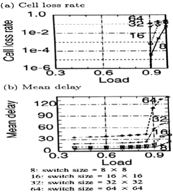
The last simulation result shown in this section is the characteristic of barrel switches greater than 8x 8 in size. Figure 10 shows the cell loss rate and mean delay characteristic of the 8 x 8, 16 x 16, 32 x 32, and 64 x 64 barrel switches with COPY routing. The cell buffer in the element switch is the CASO buffer.
Simulation results under the random traffic prove that the 64 X 64 barrel switch has adequate cell loss rate to an actual ATM switching system (less than 10"* at 85-percent load). From the result of the mean delay characteristic, the following can be seen.
At light load, few cells are held in the cell buffers in the element switches.
At the load where the cell loss rate becomes greater, a large number of cells are held in the element switches.
The mean delay characteristics calculated by the cell slot. This is a time interval in which a cell can transfer at the input/output port worse than that for e.g., the crosspoint buffer switch. However, this is not a serious problem because the absolute time of the cell slot is small at the application range of the barrel switch (200 ns for 2.4 Gbps).
V.
CONCLUSION
This paper proposed the concept and topology of a barrel switch, which has a suitable architecture for high-speed ATM switches. Two self-routing methods, i.e., for point-to-point connections only and for point-to-multipoint connections, can be implemented in a barrel switch. The topology of the switch is simple enough to allow construction by a building-block method leading to an excellent scalability. The nonblocking condition and cell loss rate/delay characteristics for the barrel switch also are addressed. Simulation results prove that less than a 64 X 64
barrel switch has adequate cell loss rate to an actual ATM switching system. However, the mean delay characteristic is worse. This will not be a serious problem in high-speed ATM switches because the cell slot is short in the high-speed switching.
More detailed performance evaluation, especially in the low cell-loss region by applying some analytical method, is a future work. Moreover, an applicable load under practical use also is a future work. The effect ofthe call admission control should also be considered.
REFERENCES
[1] Y. Shobatake, M. Motoyama, E. Shobatake, T. Kamitake, S. Shimizu, M. Noda, and K. Sakaue.A one-chip scalable 8x 8 ATM switch LSI employing shared buffer architecture. IEEE J. on Sel. Area Commun., 9, 8, pp. 1248-1254 (Oct. 1991).
[2] H. Kondoh, H. Nonaka, H. Yamanaka, T. Saito, Y. Matsuda, and M. Nakaya. Development of the Shared MuUibuffer-Type ATM Switch LSI—Imple mentation
of the Buffer Switch LSI. In: 1992 Spring Nat'l Convention Record, I.E.I.C.E., Japan, Paper C-581 (March 1992). [3] K. E. Batcher. Sorting Networks and Their Appli-cations. In: Proc. of AFIPS 1968 Spring JointComp. Conf., pp. 307-314.
[4] D. M. Dias and J. R. Jump. Analysis and simulation of buffered delta networks. IEEE Trans, on Comput., C-30, 4, pp. 273-282 (April 1981).