425
Copyright © 2011-15. Vandana Publications. All Rights Reserved.
Volume-5, Issue-3, June-2015
International Journal of Engineering and Management Research
Page Number: 425-431
Cascaded H-Bridg Multilevel Inverter Using Pic16f84a Micontroller
Shivanand .C. Masaraddi1, Prof. M.S. Aspalli2 1
M. Tech Student, Power Electronics, PDA College of Engineering, Gulbarga, Karnataka, INDIA 2Professor, Power Electronics, PDA College of Engineering, Gulbarga, Karnataka, INDIA
ABSTRACT
This paper presents a embedded controller based control of multilevel inverter for single phase Induction motor. MOSFET is used as power element. Pulse width modulation techniques (PWM), introduced three decades ago, are the most used methods to control the voltage and frequency supplied to electrical AC machines. This work proposes a new switching scheme for the cascaded H-Bridge multilevel inverter. Unlike other schemes, the proposed method is based on the symmetric regular sampling PWM with a single carrier and multiple modulating signals. On transcendental trigonometric equations that define the switching instants of the multilevel inverter are derived. This algorithm is implemented by a low-cost fixed-point microcontroller on an experimental five level cascaded inverter test-rig. Multilevel inverter has gained attention in recent years due to its high power capability associated with lower output harmonics. Several multilevel topologies have been reported in the literature and this paper focuses on asymmetric cascaded PWM technique. This technique provides reduced harmonics in the output voltage and significantly improves the RMS value of the output voltage compared to the conventional Sinusoidal Pulse Width Modulation (SPWM). A detailed study of the proposed modulation technique is carried out five-level PWM inverter test rig has been built to implement the proposed algorithm. Gating signals are generated using PIC microcontroller. The performance of the inverter has been analyzed and compared with the result obtained from theory. A scheme based on 5-level PWM inverter, which control a high performance 8-bit standard microcontroller with gate driver circuit and additional hardware is used, which allows a flexible and economical solution. The output voltage can be varied in a large range and with a good resolution. Experimental data obtained from an induction motor drive will be presented.
Keywords--- Topologies, SPWM, PWM technique,
Supply
I.
INTRODUCTION
In recent years, industry has begun to demand higher power equipment, which now reaches the megawatt level. Controlled ac drives in the megawatt range are usually connected to the medium-voltage network. Today,
it is hard to connect a single power semiconductor switch directly to medium voltage grids. For these reasons, a new family of multilevel inverters has emerged as the solution for working with higher voltage levels.
The concept of multilevel converters has been introduced since 1975. The term multilevel began with the three-level converter. Subsequently, several multilevel converter topologies have been developed. However, the elementary concept of a multilevel converter to achieve higher power is to use a series of power semiconductor switches with several lower voltage dc sources to perform the power conversion by synthesizing a staircase voltage waveform. A multilevel inverter is a power device built to synthesize a desired AC voltage from several levels of DC voltages. Multilevel inverter has been recognized to be very attractive in high voltage DC to AC conversion. It offers several advantages compared to the conventional two level inverter, in reducing switching loss and better harmonic performance, better electromagnetic compatibility and high voltage capability. Considering these advantages, multilevel inverters have been gaining considerable popularity in recent years. The benefits are especially clear for medium-voltage drives in industrial applications and are being considered for future naval ship propulsion system.
Due to many advantages, several topologies for multilevel inverter have been proposed over the years; the most popular being the diode-clamped, flying capacitor, and cascaded H-bridge structures. One aspect which sets the cascaded H-bridge apart from other multilevel inverter is the capability of utilizing different dc voltage on the individual H-bridge cells which results in splitting the power conversion amongst higher-voltage lower-frequency and lower-voltage higher-frequency inverters. The primary advantages of this structures is its simplicity and that fewer or more H-bridge cells can be cascaded in order to decrease or increase the voltage and power level respectively.
426
Copyright © 2011-15. Vandana Publications. All Rights Reserved.
In addition, several modulation and control strategies have been developed or adopted the multilevel inverters including the following: multilevel sinusoidal pulse width modulation (PWM), multilevel selective harmonic elimination, and space-vector modulation (SVM).
A multilevel converter has several advantages over a conventional two-level converter that uses high switching frequency pulse width modulation (PWM). The attractive features of a multilevel converter can be briefly summarized as follows.
● Staircase waveform quality: Multilevel converters not
only can generate the output voltages with very low distortion, but also can reduce the dv/dt stresses. Therefore electromagnetic compatibility (EMC) problems can be reduced.
● Input current: Multilevel converters can draw input current with low distortion.
● Switching frequency: Multilevel converters can operate
at both fundamental switching frequency and high switching frequency PWM. It should be noted that lower switching frequency usually means lower switching loss and higher efficiency.
Today, multilevel inverters are extensively used in high-power applications with medium voltage levels. The field applications include uses in laminators, mills, conveyors, pumps, fans, blowers, compressors and so on.
Multilevel converters do have some disadvantages. One particular disadvantage is the greater number of power semiconductor switches needed. Although lower voltage rated switches can be utilized in a multilevel converter, each switch requires a related gate drive circuit. This may cause the overall system to be more expensive and complex.
Organization of report
In chapter 2, the literature survey is described. In chapter 3, problem definition is explained.
In chapter 4, the block diagram of hardware is described. The block diagram includes power supply, single phase full bridge rectifier, control circuit (PIC16F84A), driver circuit (IR 2110) and single phase multilevel inverter are explained.
In chapter 5, experimental setup, results and input/ output waveforms are showed.
Last part of this report contains conclusion that describes how the work is concluded at the end. References which have been referred for to complete this work.
II.
RELATED WORK
Some of the related works are summarized in the following:
Leon .M Tolbert, John N. Chiasson, Zhong Du, Keith
J.McKenzie. “Elimination of harmonics in a multilevel converter with nonequal DC sources”, IEEE Trans. Ind. Appl., Vol. 41, No. 1, January / February 2005 pp. 75-82. In this paper they have studied the eliminating harmonics in a multilevel converter in which the separate dc sources vary is considered. That is given a desired fundamental output voltage. The problem is to find the switching times
(angles) that produce the fundamental while not generating specifically chosen harmonics. Assuming that the separate dc sources can be measured, a procedure is given to find all sets of switching angles for which the fundamental is produced while lower order harmonics are eliminated. This is done by first converting the transcendentalequations that specify the elimination of the harmonics into an equivalent set of polynomial equations. Then using the mathematical theory of resultants, all solutions to this equivalent problem can be found. Experimental results are presented to validate the theory. A KEY ISSUE in designing an effective multilevel inverter is to ensure that the total harmonic distortion (THD) in the voltage output waveform is small enough. To do so requires both an (mathematical) algorithm to determine when the switching should be done so as to not produce harmonics and a fast real time computing system to implement the strategy. Work was reported that presented a method to compute the switching angles for the H-bridges in a cascaded converter using the mathematical theory of resultants. In that work, a complete solution was presented for computing all possible switching angles that achieved the requisite fundamental voltage and eliminated lower order harmonics. The interest here is a cascade multilevel inverter switching at the fundamental frequency with non-equal dc sources. However, many interesting pulse width modulation (PWM) techniques have been proposed for controlling these inverters, for example where in harmonic elimination was studied by phase shifting the carrier frequency. Elimination theory and the notion of resultants can be used to eliminate the lower order harmonics in a multilevel converter that has non-equal dc sources. This method is expected to have widespread application as most multilevel converters do not have dc sources that are exactly equal.
Richa Bhargava and Amit Shrivastava “ Cascaded
427
Copyright © 2011-15. Vandana Publications. All Rights Reserved.
Modulation (SPWM). A detailed study of the proposed modulation technique is carried out five-level PWM inverter test rig has been built to implement the proposed algorithm. Gating signals are generated using PIC microcontroller. The performance of the inverter has been analyzed and compared with the result obtained from theory. A scheme based on 5-level PWM inverter, which control a high performance 8-bit standard microcontroller with gate driver circuit and additional hardware is used, which allows a flexible and economical solution. The output voltage can be varied in a large range and with a good resolution. Experimental data obtained from an induction motor drive will be presented.
The switching angles of the waveform will be adjusted to obtain the lowest output voltage THD. The harmonics orders and magnitude are depends up on the type of inverter and the control techniques. For example in single phase VSI, the output voltage waveform typically consists only of odd harmonics. The even harmonics are not present due to the half wave symmetry of the output voltage harmonics. The harmonic spectra depend on the switching frequency and the control method.
Jose Rodriguez, Jih-Sheng Lai, and Fang Zheng Peng “Multilevel Inverters: A Survey of Topologies,Conreols,and Applications”, IEEE Trans. Ind. Electron., Vol. 49, No. 4, August 2002 pp. 724-737. They have to propose multilevel inverter technology has emerged recently as a very important alternative in the area of high-power medium-voltage energy control. This paper presents the most important topologies like diode-clamped inverter (neutral-point clamped), capacitor-clamped (flying capacitor), and cascaded multi cell with separate dc sources. Emerging topologies like asymmetric hybrid cells and soft-switched multilevel inverters are also discussed. They have also presents the most relevant control and modulation methods developed for this family of converters: multilevel sinusoidal pulse width modulation, multilevel selective harmonic elimination, and space-vector modulation. Special attention is dedicated to the latest and more relevant applications of these converters such as laminators, conveyor belts, and unified power-flow controllers. The need of an active front end at the input side for those inverters supplying regenerative loads is also discussed, and the circuit topology options are also presented. Finally, the peripherally developing areas such as high-voltage high-power devices and optical sensors and other opportunities for future development are addressed.
This presents state-of-the-art multilevel technology, considering well-established and emerging topologies as well as their modulation and control techniques. Special attention\ is dedicated to the latest and more relevant industrial applications of these converters. Finally, the possibilities for future development are addressed. The modulation methods used in multilevel inverters can be classified according to switching frequency. Methods that work with high switching frequencies have many commutations for the power semiconductors in one period of the fundamental output voltage. A very popular method in industrial applications is the classic carrier-based sinusoidal PWM (SPWM) that
uses the phase-shifting technique to reduce the harmonics in the load voltage. Another interesting alternative is the SVM strategy, which has been used in three-level inverters. Methods that work with low switching frequencies generally perform one or two commutations of the power semiconductors during one cycle of the output voltages, generating a staircase waveform. Representatives of this family are the multilevel selective harmonic elimination and the space-vector control (SVC).
The author proposed brief summary of multilevel inverter circuit topologies and their control strategies. Different applications using different inverter circuits were also discussed. As mentioned in Section I, an early patent for the cascaded multilevel inverter can be traced back to 1975. However, the commercial products that utilize this superior circuit topology were not available until the mid-1990s. Today, more and more commercial products are based on the multilevel inverter structure, and more and more worldwide research and development of multilevel inverter-related technologies is occurring. This paper cannot cover or reference all the related work, but the fundamental principle of different multilevel inverters has been introduced systematically. The intention of the authors was simply to provide groundwork to readers interested in looking back on the evolution of multilevel inverter technologies, and to consider where to go from here.
L.M.Tolbert,F.Z.Peng,T.G. Habetler, “Multilevel PWM methods at low modulation indices,” IEEE Trans. Power Electronics, vol. 15, no. 4, July 2000, pp. 719-725. They have to propose at low amplitude modulation indices, existing multilevel carrier-based PWM strategies have no special provisions for this operating region, and several levels of the inverter go unused. This paper proposes some novel multilevel PWM strategies to take advantage of the multiple levels in both a diode clamped inverter and a cascaded H-bridges inverter by utilizing all of the levels in the inverter even at low modulation indices. Simulation results show what effects the different strategies have on the active device utilization. A prototype 6-level diode-clamped inverter and an 11-level cascaded H-bridges inverter have been built and controlled with the novel PWM strategies proposed.
428
Copyright © 2011-15. Vandana Publications. All Rights Reserved.
indices. While the multilevel PWM techniques developed thus far have been extensions of two-level PWM methods, the multiple levels in these inverters offer extra degrees of freedom and greater possibilities in terms of device utilization, state redundancies, and effective switching frequency. A need exists for using all of the levels in the inverter at these low modulation index-operating conditions; otherwise, the multilevel inverter loses some of its advantages over the traditional two-level inverter. Existing multilevel carrier-based PWM strategies have no special provisions when inverters operate at low amplitude modulation indices. novel carrier-based multilevel PWM strategies are proposed to increase device utilization in both a diode-clamped inverter and a cascaded H-bridges inverter at low modulation indices. One way to use all of the multiple levels in the inverter, even during low modulation periods, is to take advantage of the redundant output voltage states and to rotate level usage in the inverter during each cycle. This will reduce the switching stresses on some of the inner levels by making use of those outer voltage levels that otherwise would go unused. This procedure also enables the inverter to switch at higher frequencies during low modulation indices. This increases the frequency spectrum and hastens the dynamic response of the inverter, yet does not exceed the allowable switching loss of the active devices.
Multilevel inverters lose some of their advantages over two-level inverters if traditional carrier-based multilevel PWM methods are used at low modulation index-operating conditions. During low modulation index operation of a diode-clamped inverter, rotating the modulation waveform through different bands of carrier waveforms is possible by using line-line redundant voltage states to proficiently make use of all the levels in the inverter. PWM pulse rotation among the various H-bridges in a cascade inverter takes advantage of phase redundancies to help balance the SDCS voltage states and switch utilization.
III.
PROBLEM DEFINATION
The voltage source inverter produces an output voltage or a current with levels either zero or +
IV.
PROPOSED SYSTEM
Vdc, they are known as two level inverter. To obtain a quality output voltage or a current waveform with a minimum amount of ripple content, they require high switching frequency along with various pulse-width modulation strategies. In high power and high voltage applications, these two-level inverters have some limitations in in operating at high frequency mainly due to switching losses and constraints of device rating. The DC link voltage of a two level inverter is limited by voltage ratings of switching devices, the problematic series connection of switching devices is required to raise the the DC link voltage. By series connection, the maximum allowable switching frequency has to be more lowered. Hence harmonic reduction becomes more difficult. In addition, the two level inverters generate high frequency common-mode voltage within the motor winding which may result in motor and drive application problems. From the aspect of harmonic
reduction and high dc link voltage level, five level H-bridge multilevel inverter approach seems to be most promising alternative. The harmonic contents of a five level H-bridge multilevel inverter are less than that of a two level inverter at the same time switching frequency and the blocking voltage of the switching device is half of the dc-link voltage. A five level inverter will not generate the common mode voltages when the inverter output voltages are limited within certain available switching states. So the five level h-bridge inverter topology is used in realizing high performance, high voltage AC drives.
To overcome the problems of regular two level inverter, I have tried and developed a five level H-bridge multilevel inverter. Also H-bridge multilevel inverter requires the least number of components among all multilevel converters to achieve the same number of level. In my work, MOSFET(IRF 450) switches, control circuit(PIC16F84A), and two unequal DC source are used. I have shown the waveforms of five level H-bridge multilevel inverter, observed the input/output voltage waveforms and gate pulses.
The proposed block diagram as shown in figure 4.1
Single phase full bridge rectifier: In the process of
rectification ac voltage (230V, 1Ф, 50Hz) is converted into
dc voltage. To reduce ripples in the output of the rectifier a capacitor filter is used. In the proposed scheme the bridge rectifier is used to provide the dc voltage to their inverter circuit. The bridge rectifier having four IN4007diodes and features of these diodes are;
• Diffused Junction
• High Current Capability and Low Forward Voltage Drop • Surge Overload Rating to 30A Peak
• Low Reverse Leakage Current
Figure 4.1 Block diagram of proposed system
Power supply: In the proposed system the required DC voltages are:
(1) +5V for PIC16f84a microcontroller (2) +12V for gate firing pulses to MOSFET
429
Copyright © 2011-15. Vandana Publications. All Rights Reserved.
regulator IC should be more than its output voltage, transformer secondary voltage is 12V. This low voltage is rectified with the help of bridge rectifier. The ripples are minimized with the help of filter capacitor to get a smooth DC supply.
The rectified ac (dc voltage) is fed to corresponding LM7812 / LM7805 voltage regulator to get respective voltages. The regulated +5V DC voltage is obtained by using a regulator IC 7805. The regulated +5V DC is given to PIC16f84a. The regulated +12V is obtained by using IC 7812 and this voltage is given for gate pulses to MOSFET.
Capacitor filter: The ripples in the pulsating DC are removed and pure DC is obtained by using a capacitor filter.
Voltage regulators: Three terminal regulators is available with several fixed output voltages making them useful in a wide range of applications. Fixed voltage regulators these devices can be used with external components to obtain adjustable voltages and currents.
The positive terminal of the capacitor is connected to the input pin of the 7812 regulator for voltage regulation. An output voltage of 12V obtained from the output pin of 7812 is fed as the supply to the pulse amplifier.
An output voltage of 5V obtained from the output pin of 7805 is fed as the supply to the micro controller. From the same output pin of the 7805, a LED is connected in series with the resistor to indicate that the power is ON. Driver circuit
IR2110- High side and Low side driver: Some of the features of IR 2110 are:
Floating channel designed for bootstrap operation
Gate drive supply range from 10 to 20V
Under voltage lockout for both channels
3.3V logic compatible
Separate logic supply range from 3.3V power ground + 5V power ground + 5V offset
CMOS Schmitt-triggered inputs with pull down
Cycle by cycle edge-triggered shutdown logic
Matched propagation delay for both channels outputs in phase with inputs
Driver is also called as power amplifier because it is used to amplify the pulse output from micro controller. The IR2110 is a high voltage, high speed power MOSFET driver with independent high and low side referenced output channels.It is fully operational to +500V or +600V and tolerant to negative transient voltage dV/dt immune. Logic inputs are compatible with standard CMOS or LSTTL output, down to 3.3V logic. The output drivers feature a high pulse current buffer stage designed for minimum driver cross-conduction.
Propagation delays are matched to simplify use in high frequency applications. The floating channel can be used to drive an N-channel power MOSFET or IGBT in the high side configuration which operates up to 500 or 600 volts.
Multilevel inverter: In hardware setup two H bridge multilevel inverters H1 and H2 are used. These H bridge multilevel inverters madeup of total eight IRF460N
MOSFET switches. H bridge multilevel inverter H1 is designed by four MOSFET switches and also H bridge multilevel inverter H2 designed by four MOSFET switches.Two unequal dc sources to generate an equal step five level output. The single phase multilevel inverter consists of two H-bridges. The main H-bridge (H1) is connected to a dc source of Vdc1 and the second bridge (H2) is connected to a dc source of Vdc2. By suitably opening and closing the switches of H1, the output voltage v1 can be made equal to –Vdc1, 0, or +Vdc1 similarly the output voltage of H2 can be made equal to –Vdc2, 0, or +Vdc2. Therefore, the output voltage of the converter can have five possible values Vdc1, -Vdc1, 0,Vdc2, and – Vdc2. The output of multilevel H-bridge inverter connecting across the resistor load(1M ohm) or single phase induction motor (0.5hp).
Control unit: In this project the hardware is implemented using the PIC microcontroller PIC16F84A. The advantages of the PIC microcontroller is that the instruction set of this controller are fewer than the usual microcontroller. Unlike conventional processors, which are generally complex, instruction set computer (CISC) type, PIC microcontroller is a RISC processor. The advantages of RISC processor against CISC processor are RISC instructions are simpler and consequently operate faster, A RISC processor takes a single cycle for each instruction, while CISC processor requires multiple clocks per instruction (typically, at least three cycles of throughput execution time for the simplest instruction and 12 to 24 clock cycles for more complex instruction), which makes decoding a tough task, and the control unit in a CISC is always implemented by a micro-code, which is much slower than the hardware implemented in RISC. Overall the RISC processor can provide processing power more than three times of a CISC processor in a particular field of application.
PIC16F84A microcontroller is used to generate triggering pulse for MOSFETs. It is used to control the output of the inverters. Micro controller have more advantage compare then analog circuits and micro processor such as fast response, low cost, small size and etc. The PIC16F84A belongs to the mid-range family of the PIC microcontroller devices. The program memory contains 1K words, which translates to 1024 instructions, since each 14-bit program memory word is the same width as each device instruction. The data memory (RAM) contains 68 bytes. Data EEPROM is 64 bytes.
V.
RESULT AND DISCUSSION
As said earlier, due to the limitations on the maximum voltage range (300 volts peak to peak) of the storage oscilloscope TDS2024B the experiment is done on 100Vrms (2x141.42 = 283 peak to peak).
The hardware implementation of cascaded H-bridge multilevel
430
Copyright © 2011-15. Vandana Publications. All Rights Reserved.
The ripples in the pulsating DC are removed and pure DC is obtained by using a capacitor filter. The positive terminal of the capacitor is connected to the input pin of the 7812 regulator for voltage regulation. An output voltage of 12V obtained from the output pin of 7812 is fed as the supply to the pulse amplifier. An output voltage of 5V obtained from the output pin of 7805 is fed as the supply to the micro controller. From the same output pin of the 7805, a LED is connected in series with the resistor to indicate that the power is ON. Then the pulse signals (control signals) from PIC 16f844a is subjected to the MOSFET switches through the driver circuit (IR2110).In this project there are one driver circuit for two switches, so for eight MOSFET switches total four driver circuits are used.
There are number of modulation control techniques such as sinusoidal PWM method (SPWM), space vector PWM method (SVPWM), selective harmonic elimination method (SHE), and active harmonic elimination method, and they all can be used for inverter modulation control. For the proposed inverter control, a sensible modulation control method is the fundamental frequency switching control for high output voltage and Sinusoidal PWM control for low output voltage. In this paper, fundamental frequency switching control is used in H-bridge MLI.
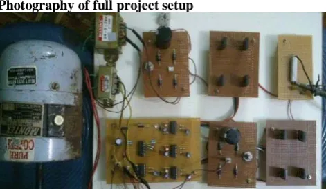
Photography of full project setup
Figure 5.1 Photography of cascaded H-bridge multilevel inverter using embedded controller
Figure 5.2 Input voltage(24V)
Figure 5.3 input voltage(48V)
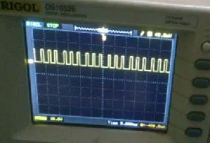
Figure 5.4 Switching pulse H-bridge H1(5V)
Figure 5.5 Driver output pulse (10V)
431
Copyright © 2011-15. Vandana Publications. All Rights Reserved.
Figure 5.7 Driver output pulse (10V)
Figure 5.8Output voltage
VI.
CONCLUSION
In this project sinusoidal PWM scheme is used for modulation control. In cascaded H-bridge multilevel inverter separated unequal DC sources are used to generate sinusoidal output. A fundamental switching scheme is used and produces a nearly sinusoidal output. This cascaded inverter design is to get the improved sinusoidal output of an inverter and gives less THD%. The elimination of harmonics in a cascade H-bridge multilevel inverter by considers the inequality of separated dc source. The PWM techniques have been analyzed for the cascaded H-Bridge multilevel inverter. A Micro-controller based gating circuit generates the pulses required by the inverter.
The induction motor drive system is successfully fabricated and tested. This can be important in the high power quality cascaded multilevel inverters which require several voltage sources and knowledge of the dc voltage levels. Applications of the cascaded multilevel inverter include naval ship propulsion which necessitates high power quality.
A PWM modulator, suitable for voltage control, was presented and tested with a 0.5 H.P single-phase induction motor fed by an MOSFET 5-level PWM inverter. In this system high performance 8- bit microcontroller with gate driver circuit and additional hardware.
REFERENCES
[1]. M. Doe, G.. Hanes,” Application examples using the 8XCI 96MC/MD microcontroller. In "AP- 483". Intel Corporation”, 1993.
[2]. M.H. Rashid, “Power electronics: circuits. Devices and applications”. Prentice-Hall, 1993.
[3]. B.K. Boss,” Power electronics circuit and drives”. [4].Dr. R. Seyezhai,”Carrier Overlapping PWM methods for asymmetrical multimeter inverter”. International Journal of Engineering Science and Technology, Vol.3 No.8 August 2011.
[5]. Keith Corzine and Yaakov Familiant “A New Cascaded Multilevel H-Bridge Drive.”IEEE Transaction on Power Electronics, Vol.17, No.1, January2002.
[6]. R. Bojoi,A. Tenconi F. Profumo, G.. Griva and D. Martinello,”Complete analysis and comparative study of digital modulation techniques for dual three-phaseAC motor drives.” IEEE Power Electronics Specialists Conf. (PESC) Cairns, Australia, Vol. 2, pp.851–857 2002. [6]. H.S.Pateland and R.G. Hoft,“Generalized harmonic elimination and voltage control in thyristor inverters: Part- I harmonic elimination,” IEEE Trans. Industry Applications,vol. 9, pp. 310-317 May/June 1973.
[7]. Jon Are Soul, Marta Malians and Tore Undeland, “STATCOM - Based Indirect Torque Control of Induction Machines during Voltage Recovery after Grid Faults ",
IEEE Transactions on Power Electronics, Vol. 25, No. 5, pp.1240-1250 May2010.