Organized by C.O.E.T, Akola & IWWA, Amravati Center. Available Online at www.ijpret.com515
INTERNATIONAL JOURNAL OF PURE AND
APPLIED RESEARCH IN ENGINEERING AND
TECHNOLOGY
A PATH FOR HORIZING YOUR INNOVATIVE WORK
SPECIAL ISSUE FOR
NATIONAL LEVEL CONFERENCE
"SUSTAINABLE TECHNOLOGIES IN
CIVIL ENGINEERING"
INTRODUCTION OF COMPLEX MATERIAL
IN THE CONSTRUCTION OF MULTISTORIED BUILDINGS
PROF. A. S. GAWANDE, PROF. H. C. MULEY
1. Asst.Prof.@ Civil Dept. COET Akola;
2. IIndyear, M.E. Structure, COET Akola
Accepted Date: 13/03/2015; Published Date: 01/04/2015
Abstract: Construction of reinforced concrete multistoried buildings was in practice from a long time & still in large use in India due to various advantages like easy availability of materials, workmanship, and no skilled workmanship is essentially required. Hence reinforced concrete construction is extensively used not only in metropolitan cities but also in rural areas. After the recent earthquakes every multistoried building is now designed for earthquake forces, but generally for earthquake resistant design reinforced concrete structure gives uneconomical design. Every construction materials have their own limitations, advantages & disadvantages. In present work it is concentrated on use of composite construction to study it’s effectiveness in multistoried buildings, especially in earthquake resistant buildings. In this seminar it is tried to bring attention towards use of composite construction for multistoried buildings although it is largely ignored in India despite of it’s obvious benefits.
Keywords-Multistoried Buildings, Construction
Corresponding Author: PROF. A. S. GAWANDE
Co Author: PROF. H. C. MULEY
Access Online On:
www.ijpret.com
How to Cite This Article:
A. S. Gawande, IJPRET, 2015; Volume 3 (8): 515-534
Organized by C.O.E.T, Akola & IWWA, Amravati Center. Available Online at www.ijpret.com516
INTRODUCTION
Organized by C.O.E.T, Akola & IWWA, Amravati Center. Available Online at www.ijpret.com517
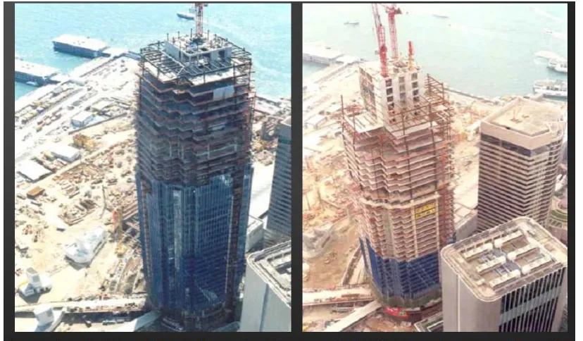
Fig.1 World’s tallest buildings
In developed countries a very large percentage of multi –storied buildings are built with steel where as steel is hardly used in construction of multi-storied frames in India even though it has proved too be a better material than reinforced concrete.
Organized by C.O.E.T, Akola & IWWA, Amravati Center. Available Online at www.ijpret.com518
Fig. 2:
1) USE OF COMPOSITE CONSTRUCTION IN MULTISTORIED BUILDING :-
Organized by C.O.E.T, Akola & IWWA, Amravati Center. Available Online at www.ijpret.com519
The numbers of structures are constructed using composite structure in most of the advanced countries like Britain, Japan and America but this technology is largely ignored in India despite its obvious benefits.
In composite structure the advantage of bonding property of steel and concrete is taken in to consideration so that they will act as a single unit under loading. These essentially different materials are completely compatible and complementary to each other; they have almost the same thermal expansion; they have an ideal combination of strengths with the concrete efficient in compression and the steel in tension; concrete also gives corrosion protection and thermal insulation to the steel at elevated temperatures and additionally can restrain slender steel sections from local or lateral-torsional buckling. In conventional composite construction, concrete rests over steel beam, under load these two component acts independently and a relative slip occurs at the interface of concrete slab and steel beam, which can be eliminated by providing deliberate and appropriate connection between them. So that steel beam and slab act as composite beam and gives behavior same as that of Tee beam. In steel concrete composite columns both steel and concrete resists external loads and helps to limit sway of the building frame and such column occupies less floor area as compared to reinforced concrete. The number of studies related to economy of the composite construction shows that the composite construction are economical, light weighted, fire and corrosion resistant and due to fast track construction building can be utilize or occupied earlier as compared to reinforced concrete structure.
The extent to which the components or parts of a building structure should embody all steel construction, be constructed entirely in reinforced concrete, or be of composite construction depends on the circumstances. It is a fact, however, that engineers are increasingly designing composite and mixed building systems of structural steel and reinforced concrete to produce more efficient structures when compared to designs using either material alone.
It should be added that the combination of concrete cores, steel frame and composite floor construction has become the standard construction method for multi-storey commercial buildings in several countries. Much progress has been made, for example in Japan, where the structural steel/reinforced concrete frame is the standard system for tall buildings. The main reason for this preference is that the sections and members are best suited to resist repeated earthquake loadings, which require a high amount of resistance and ductility.
Organized by C.O.E.T, Akola & IWWA, Amravati Center. Available Online at www.ijpret.com520
elements, such as isolated beams, columns and slabs, whilst they are of high quality and resistance, they are also, in many cases, expensive. This is the case particularly for buildings with small columns spacing, floor beam spans well below 9 m and low loadings. On the other hand, composite floor construction is highly competitive if spans are increased to 12, 15 or even 20 m. There is, of course, a demand for larger column-free spans in buildings to facilitate open planning or greater flexibility in office layout.
A further important consideration is that the use of rolled steel sections, profiled metal decking and/or prefabricated composite members speeds up execution. For maximum efficiency and economy the joints should be cheap to fabricate and straight forward to erect on site.
Many experts feel that the further development of steel framed buildings depends largely on the use of composite construction.
3) ADVANTAGE OF (STEEL+CONCRETE) COMPOSITE CONSTRUCTION
Most effective utilization of materials viz. concrete in compression and steel in tension.
High ductility of steel material leads to better seismic resistance of the composite section. Steel component can be deformed in a ductile manner without premature failure and can withstand numerous loading cycles before fracture.
Steel component has the ability to absorb the energy released due to seismic forces.
Ability to cover large column free area. This leads to more usable space. Area occupied by the composite column is less than the area occupied by the RCC Column.
Faster construction by utilizing rolled and /or pre-fabricated components. Also speedy construction facilitates quicker return on the invested capital.
Quality of steel is assured since it is produced under controlled environment in the factory. Larger use of steel in composite construction compared to that in RCC ensures better quality control for the major part of the structure.
Cost effectiveness based on life cycle cost analysis because steel structures can be maintained easily and less frequent repairment is required for steel structure.
Organized by C.O.E.T, Akola & IWWA, Amravati Center. Available Online at www.ijpret.com521 Keeping span/loading unaltered, smaller structural steel section are required compared to non-composite construction. Therefore reduction in overall weight of the composite structure compared to the RCC construction results less foundation costs.
Cost of formwork is lower compared to RCC construction.
Cost of handling and transportation is minimized because major part of the structure is fabricated in the workshop.
The steel and steel concrete composite construction is more resistant against terrorist activities as compared to RCC Construction.
Composite sections have higher stiffness and hence experience less deflection than the non-composite steel sections.
Steel frames are faster to erect compared with reinforced concrete frames. The availability of the building in a shorter period of time results in economic advantages to the owner due to shorter period of deployment of capital, without return. For example, at the time the steel-framed Empire State Building was completed, the tallest reinforced concrete building, the exchange building in Seattle, had attained a height of only 23 storeys.
4) COMPOSITE STRUCTURE
4.1) GENERAL:-
Organized by C.O.E.T, Akola & IWWA, Amravati Center. Available Online at www.ijpret.com522
4.2) COMPOSITE ELEMENTS :-
The primary structural components use in composite construction consists of the following elements.
1. Composite slab
2. Composite beam
3. Composite column
4. shear connector
4.2.1) Composite Slab :-
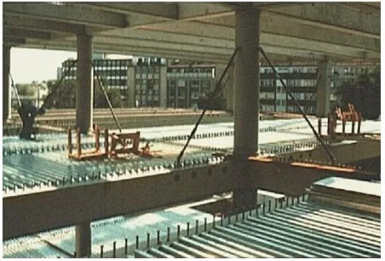
Traditional steel-concrete floors consist of rolled or built-up structural steel beams and cast in-situ concrete floors connected together using shear connectors in such a manner that they would act monolithically (Fig.3.1). The principal merit of steel-concrete composite construction lies in the utilization of the compressive strength of concrete slabs in conjunction with steel beams, in order to enhance the strength and stiffness of the steel girder.
More recently, composite floors using profiled sheet decking have become very popular in the West for high rise office buildings. Composite deck slabs are particularly competitive where the concrete floor has to be completed quickly and where medium level of fire protection to steel work is sufficient. However, composite slabs with profiled decking are unsuitable when there is heavy concentrated loading or dynamic loading in structures such as bridges. The alternative composite floor in such cases consists of reinforced or pre-stressed slab over steel beams connected together to act monolithically.
A typical composite floor system using profiled sheets is shown in Fig.3.2. There is presently no Indian standard covering the design of composite floor system using profiled sheeting.
Organized by C.O.E.T, Akola & IWWA, Amravati Center. Available Online at www.ijpret.com523
Fig.4:
Fig 5: The usual practice for commercial and industrial buildings is to construct the floors using metal decking which is embossed to provide composite action.
The main structural and other benefits of using composite floors with profiled steel decking are:
Savings in steel weight are typically 30% to 50% over non-composite construction.
Greater Stiffness of composite beams results in shallower depths for the same span. Hence lower storeys heights are adequate resulting in savings in cladding costs, reduction in wind loading and savings in foundation costs.
Organized by C.O.E.T, Akola & IWWA, Amravati Center. Available Online at www.ijpret.com524
The steel decking performs a number of roles, such as :-
It support loads during construction and acts as a working platform.
It develops adequate composite action with concrete to resist the imposed loading.
It transfers in-plane loading by diaphragm action to vertical bracing or shear walls.
It stabilize the compression flanges of the beams against lateral bucking, until concrete hardens.
It reduces the volume of concrete in tension zone.
It distributes shrinkage strains, thus preventing serious cracking of concrete.
4.2.2) Composite Beams :-
In conventional composite construction, concrete slabs rest over steel beams and are supported by them. Under load these two components act independently and a relative slip occurs at the interface if there is no connection between them. With the help of a deliberate and appropriate connection provided between them can be eliminated. In this case the steel beam and the slab act as a “composite beam” and their action is similar to that of a monolithic Tee beam. Though steel and concrete are the most commonly used materials for composite beams, other materials such as pre-stressed concrete and timber can also be used. Concrete is stronger in compression than in tension, and steel is susceptible to bucking in compression. By the composite action between the two, we can utilize their respective advantage to the fullest extent. Generally in steel-concrete composite beams, steel beams are integrally connected to prefabricated or cast in situ reinforced concrete slabs.
Composite Action In Beams :-
Organized by C.O.E.T, Akola & IWWA, Amravati Center. Available Online at www.ijpret.com525
between them when the beam is loaded. Thus, each component will act independently. With the help of deliberate and appropriate connection between concrete slab and steel beam the slip can be minimized or even eliminated altogether. If slip at the interface is eliminated or drastically reduced, the slab and steel member will act together as a composite unit. The resulting increase in resistance will depend on the extent to which slip is prevented. The degree
Fig.6: Simply-supported composite beam
of the interaction depends mainly on the degree of shear connection used. Slip is zero at mid-span and maximum at the support of the simply supported beam subjected to uniformly distributed load. Hence, shear is less in connectors located near the centre and maximum in connectors located near the support.
Organized by C.O.E.T, Akola & IWWA, Amravati Center. Available Online at www.ijpret.com526
Fig.7: Typical Beam Cross Sections
Organized by C.O.E.T, Akola & IWWA, Amravati Center. Available Online at www.ijpret.com527
Organized by C.O.E.T, Akola & IWWA, Amravati Center. Available Online at www.ijpret.com528
Advantages of composite beams :-
1. Keeping the span and loading unaltered, amore economical steel section 9in terms of depth and weight) is adequate in composite construction compared with conventional non-composite construction.
2. Encased steel beam sections have improved fire resistance and corrosion.
3. It satisfied requirement of long span construction – a modern trend in architectural design.
4. Composite construction is amenable to fast track construction because of use of rolled steel sections.
5. Composite sections have higher stiffness than the corresponding steel sections and thus the deflection is lesser.
6. Permits easy structural repairs/modification.
7. Provides considerable flexibility in design and ease of fabrication.
8. Enables easy construction scheduling in congested sites.
9. Reduction in overall weight of the structure and there by reduction in foundation cost.
Organized by C.O.E.T, Akola & IWWA, Amravati Center. Available Online at www.ijpret.com529
4.2.3) Composite Columns :-A steel concrete composite column is a compression member, comprising either of a concrete encased hot rolled steel section or a concrete filled hollow section of hot rolled steel. It is generally used as a load bearing member in a composite framed structure. Composite members are mainly subjected to compression and bending. At present there is no Indian standard code covering the design of composite column. The method of design in this report largely follows EC4, which incorporates latest research on composite construction. Indian standard for composite construction IS 11384-1985 does not make any specific reference to composite columns. This method also adopts the European bucking curves for steel columns as a basic of column design.
Organized by C.O.E.T, Akola & IWWA, Amravati Center. Available Online at www.ijpret.com530
Fig.11: Typical cross-sections of concrete filled tubular sections
Fig.12:
Organized by C.O.E.T, Akola & IWWA, Amravati Center. Available Online at www.ijpret.com531
Load resisting mechanism :-
In composite columns both the steel and concrete would resists the external loading by interacting together by bond and friction. Additional reinforcement in the concrete encasement prevents excessive spalling of concrete both under normal load and fire conditions.
Construction method :-
With the composite construction, the steel sections the initial construction loads, including the weight of structure during construction. Concrete is later cast around the steel section. The concrete and steel are combined in such a fashion that the advantages of both the materials are utilized, effectively in composite column. The lighter weight and higher strength of steel permits the use of smaller and lighter foundations. The subsequent concrete addition enables the building frame to easily limit the sway and lateral deflections.
THE ADVANTAGES OF COMPOSITE COLUMNS ARE :-
1) Increased strength for a given cross sectional dimension.
2) Increased stiffness, leading to reduced slenderness and increased bulking resistance.
3) Good fire resistance in the case of concrete encased columns.
4) Corrosion protection in encased columns.
5) Significant economic advantages over either pure structural steel or reinforced concrete alternatives.
6) Identical cross sections with different load and moment resistances can be produced by varying steel thickness, the concrete strength and reinforcement. This allows the outer dimensions of a column to be held constant over a number of floors in a building, thus simplifying the construction and architectural detailing.
7) Erection of high rise building, thus simplifying the construction and architectural detailing.
8) Erection of high rise building in an extremely efficient manner.
Organized by C.O.E.T, Akola & IWWA, Amravati Center. Available Online at www.ijpret.com532
4.2.4) Shear Connectors :-
The total shear force at the interface between concrete slab and steel beam is approximately eight times the total load carried by the beam. Therefore, mechanical shear connectors are required at the steel-concrete interface. These connectors are designed to (a) transmit longitudinal shear along the interface, and (b) Prevent separation of steel beam and concrete slab at the interface.
Shear connectors are essential for steel concrete composite construction as they integrate the compression capacity of supported concrete slab with supporting steel beams to improve the load carrying capacity as well as overall rigidity. The maximum shear force lies at the neutral axis. In case of composite beams the neutral axis of the section generally lies at the bottom of the concrete slab. This leads to separation of concrete slab from the steel beam. To avoid this there should be prefect bond between concrete and steel. This can he achieved by providing shear connectors at the interface of concrete and steel. Though steel to concrete bond may help shear transfer between the two to certain extent, yet it is neglected as per the codes because of its uncertainty. All codes therefore, specify positive connectors at the interface of steel and concrete. The shear connectors are designed to transmit longitudinal shear along the interface and horizontal shear between steel beam and concrete slab, ignoring the effect of any bond between the two. Shear connectors prevent separation of steel beam and concrete slab at the interface and also resist uplift force at the steel concrete interface. Commonly used types of shear connectors as per IS: 11384-1985. There are three main types of shear connectors; rigid shear connectors, flexible shear connectors and anchorage shear connectors.
Organized by C.O.E.T, Akola & IWWA, Amravati Center. Available Online at www.ijpret.com533
Types of shear connectors :-
Rigid type :-
As the name implies, these connectors are very stiff and they sustain only a small deformation while resisting the shear force. They derive their resistance from bearing pressure on the concrete, and fail due to crushing of concrete. Short bars, angles, T-sections are common examples of this type of connectors. Also anchorage devices like hoped bars are attached with these connectors to prevent vertical separation.
Flexible type :-
Headed studs, channels come under this category. These connectors are welded to the flange of the steel beam. They derive their stress resistance through bending and undergo large deformation before failure. The stud connectors are the types used extensively. The shank and the weld collar adjacent to steel beam resist the shear loads whereas the head resists the uplift.
Bond or anchorage type :-
It is used to resist horizontal shear and to prevent separation of girder from the concrete slab at the interface through bond. These connectors derived form the resistance through bond and anchorage action.
CONCLUSION:-
A look at world-class high-rise steel-concrete framed buildings constructed in various parts of world may inspire one to become a structural engineer of such a class of structures.
Many experts feel that the further development of steel framed buildings depends largely on the use of composite construction.
REFERENCES
1. D. K. Paul “Simplified seismic analysis of framed buildings on hill slopes Bulletin of Indian Society of earthquake technology, Vol 30, no4,paper 335,Dec 1993, pp 113-124
Organized by C.O.E.T, Akola & IWWA, Amravati Center. Available Online at www.ijpret.com534
3. Satish Annigeri, Ashok k Jain “Torsional Provisions for asymmetrical multi-storey buildings in I.S.1893,” International Journal of structures, vol14, no 2, paper no 139, Dec 94, pp 115- 142.
4. Satish kumar & D. K. Paul 3.D.Analysis of Irregular Buildings with Rigid Floor Diaphragms Bulletin of Indian Society of earthquake technology, Vol 31, no4, paper no 335, Sept 1994, pp 141-154
5. Dr. S. R. Murthy & K. Latha Journal of Structural Engineering , Vol 37,No 4,Octomber-November 2010, pp256-262
6. BIS (2002). “IS 1893 (Part 1)-2002: Indian Standard Criteria for Earthquake Resistant Design of Structures, Part 1 – General Provisions and Buildings (Fifth Revision)”, Bureau of Indian Standards, New Delhi
7. Paz, M., Structural Dynamics: theory and computation. Second edition, CBS publishers and distributors pvt. ltd.