A NUMERICAL STUDY OF THE EFFECT OF A BELOW-WINDOW
CONVECTIVE HEATER ON THE HEAT TRANSFER RATE
FROM A COLD RECESSED WINDOW
Patrick H. Oosthuizen
*Queen's University, Kingston, Ontario, K7L 3N6 Canada
A
BSTRACTThe convective heat transfer to a window below which is mounted a natural convective heater has been numerically studied. The flow has been assumed to be three-dimensional and steady and to involve regions of laminar and turbulent flow. Fluid properties have been assumed constant except for the density change with temperature which leads to the buoyancy forces. The solution has been obtained using a commercial cfd code. Results have been obtained for a Prandtl number of 0.7. The effects of changes in the flow variables on the window Nusselt number and on the flow and temperature distributions have been examined.
Keywords: Natural Convection, Transition, Window Heat Transfer, Flow Pattern.
* Email: [email protected]
1.
INTRODUCTION
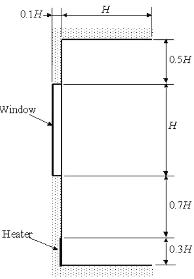
For various reasons, such as increasing thermal comfort, convective heaters are often mounted below a cold window in buildings in cold climates. The presence of the heater alters the flow and temperature distributions in the room near the window and the rate of convective heat transfer to the window. The nature of these changes has been numerically studied here. When the heater output is low the cold downward flow from the window reaches the floor leading to a cold air layer forming near the floor. At higher heater outputs the hot upward flow from the heater is strong enough to divert the cold flow from the window away from the floor. The basic situation considered in the present study is shown in Figs. 1 and 2 and is, as can be seen from these figures, a very approximate model of most real situations. Here, the heater and the window are both represented by plane isothermal sections, the window section being colder and the heater section being hotter than the room air far from the wall containing the window and the heater. The isothermal section representing the heater is in the plane of the wall containing the window while the isothermal section representing the window is recessed into the wall as shown in Fig. 1. As indicated in Fig. 2 the heater width has been assumed to be greater than the window width which leads to a complex three-dimensional flow near the vertical edges of the window. The main reasons for undertaking the present study were to determine the conditions required to ensure that the cold downward flow from the window is diverted away from the floor by the hot upward flow from the heater, to determine whether the conditions under which the upward diversion of the cold window flow occurs are different in laminar and turbulent flows, and to determine the effect that the upward diversion of the cold
window flow has on the window heat transfer. Fig. 1 Side view of situation considered.
Frontiers in Heat and Mass Transfer
Frontiers in Heat and Mass Transfer (FHMT), 2, 013004 (2011) DOI: 10.5098/hmt.v2.1.3004
Global Digital Central ISSN: 2151-8629
Fig. 2 Front view of situation considered.
There have been a number of studies of flow near window-wall heater systems typical of these being those undertaken by Turkoglu and Yucel (1995), Savin (1991), Shia-hui and Peterson (1995), Lankhorst and Hoogendoorn (1990), and Spolek (1986). Studies of thermal comfort near heaters and windows have been undertaken by, for example, Larson and Moshfegh (2002), Jurelionis and Edmundas (2008) and Kruger (1996). There have also been a number of basic studies of flow in enclosures with heated and cooled wall sections, typical of these being studies undertaken by Kulkarni and Cooper (1995), Mohamad et al. (2006), and Sigey et al. (2004). The results obtained in these studies have some relevance to the present work. Many numerical studies of the convective heat transfer between a window system and a room have been undertaken these also having relevance to the present work. The majority of these studies are based on the assumption that the flow remains laminar and steady, examples being those of Collins et al. (2002a; 2002b), Oosthuizen et al. (2005), Oosthuizen (2005; 2006a; 2006b) and Ye et al. (1999) although there are some studies in which transition from laminar to turbulent flow over the window system has been considered, e.g., see Oosthuizen (2009).
Both laminar and turbulent flow are considered in the present study. The numerical approach used here to determine when turbulence develops, i.e., solving the Reynolds averaged governing equations together with a turbulence model and then monitoring the solutions obtained with increasing Rayleigh numbers to determine when significant turbulence effects develop has been used quite extensively used for forced convective flows, e.g., see the early studies by Savill (1993), Schmidt and Patankar (1991), Plumb and Kennedy (1977), and Zheng et al. (1998). The results obtained in these studies indicate that while k-epsilon turbulence models do not give good predictions of transition in all cases they do appear to give acceptable results for the type of situation being considered here. Some work on the use of this approach in natural convective flows has also been undertaken, e.g., see Albets-Chico et al. (2008). Studies of window related transitional and turbulent flows are described by Coussirat et al. (2008), Manz (2003), Oosthuizen and Naylor (2009) and Xaman et al. (2005). More general numerical studies of turbulent flows in buildings are described for example by Rohdin et al. (2007), Zhang et al. (2007), Kuynik et al. (2007), Stamou and Katsiris (2006) and Posner et al. (2003).
Although there have been a number of studies of flow near window-wall heater systems there still appears to be the need for more basic work in this area to more clearly define how the geometric arrangement involved affects the flow and heat transfer rate. It was for this reason that the present study was undertaken. The present study, as is the case in many of the previous studies, considers only the convective heat transfer. In window heat transfer situations, the radiant heat transfer can, of course, be very important and can interact with the convective flow.
2.
SOLUTION PROCEDURE
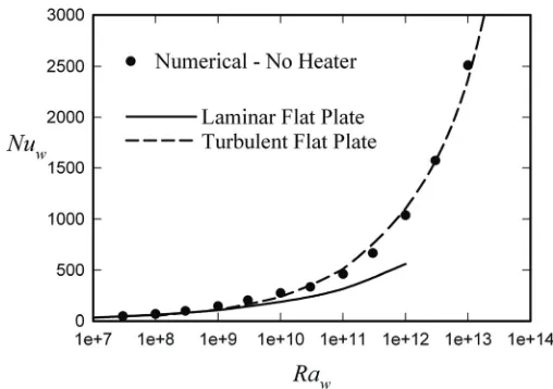
The flow has been assumed to be steady and, in general, to involve regions of laminar and turbulent flow. The fluid properties have been assumed constant except for the density change with temperature that gives rise to the buoyancy forces, this being dealt with using the Boussinesq approach. The mean flow has been assumed to be steady. The solution has been obtained using the Reynolds averaged Navier-Stokes equations in conjunction with the Standard k-epsilon turbulence model including full buoyancy force effects. The governing equations have solved using the commercial CFD code FLUENT. The temperature of the fluid far from the plate has been assumed to be constant and specified. Radiant heat transfer effects have been neglected. The boundary conditions assumed were basically that the velocity was zero on all solid surfaces, that the temperature was specified on the surface of the “window” and on the surface of the heater, that the temperature gradient was zero normal to all other solid surfaces, that the pressure was equal to the ambient pressure on the outer surface of the solution domain and that any fluid entering through this outer surface was at ambient temperature and crossed the outer surface at right angles to the surface, and that the flow was symmetrical about the vertical center-plane through the window and heater. Extensive grid- and convergence criterion independence testing was undertaken. This indicated that the heat transfer results presented here are to within 1% independent of the number of grid points and of the convergence-criterion used. An indication of the adequacy of the numerical model is also given by comparing the results obtained in the present study for the natural convective heat transfer rate to the window for the case where there is no heater with mean lines through existing experimental results for laminar and turbulent natural convective flow over a vertical isothermal flat plate. Such a comparison is shown in Fig. 3, which is discussed further below, and good agreement between the present numerical results and the mean line through existing experimental results will be seen to be obtained.
Fig. 3 Variation of window Nusselt number with Rayleigh number for the case where there is no heater. The lines show the variations for a vertical isothermal flat plate deduced from experimental measurements for the cases where the flow is laminar and where it is turbulent.
3.
RESULTS
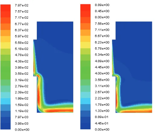
Fig. 4 Velocity contours on vertical center-plane for Raw = 108 (left)
and for Raw = 3x10¹² (right) for the case where there is no
heater.
1. The Rayleigh number, Raw , based on the “window” height
and the window-air temperature difference, i.e.:
3F w
w
g
H
Ra
T
T
(1) 2. The Prandtl number, Pr.3. The dimensionless width of the “window”, W = w / H. 4. The dimensionless width and height of the heater, i.e.
Wh= wh / H and Hh = hh / H.
5. The dimensionless height of the bottom of the window from the floor and the dimensionless height of the ceiling from the top of the window, i.e., Bw = bw / H and Cw = cw / H.
6. The dimensionless recess depth of the window Dr = dr / H
The ratio of the heater to room temperature difference to the room to window temperature difference = (Th – TF)/(TF –
Tw).
Because of the application being considered results have only been obtained for Pr = 0.7, i.e., the approximate value for air. Results have also only been obtained for the case where the “window” surface is at a lower temperature than the room air. Results will only be given here for the case where W = 2, Wh = 2.5, Hh= 0.3, Bw = 1, Cw = 0.5, and Dr =
0.1. Results obtained with other values of these parameters show the same basic characteristics as those presented here. Therefore, the solution parameters are RaH, and
.
The range of Rayleigh numberscovered in the present work is such that laminar flow exists at the lower values of Rayleigh number considered and turbulent flow exists at the higher values of Rayleigh number considered.
The mean heat transfer rates to the window and from the heater have been expressed in terms of the mean Nusselt numbers, Nuw and
Nuh, based on H and hh respectively, i.e., in terms of:
and
'
'
(
)
(
)
w h h
w h
F w h F
H
Nu
q
Nuq
k T
T
k T
T
h
(2)where qw
'
and qh'
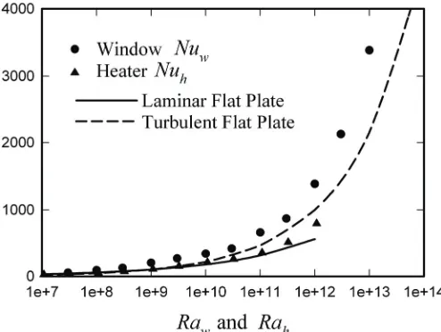
are the mean heat transfer rates from the window surface and the heater surface. In addition to the ‘window’ Rayleigh number, Ra , and ‘heater’ Rayleigh number, Ra , will also be used, thisFig. 5 Variation of window and heater Nusselt numbers with Rayleigh number for
Fig. 6 Variation of window and heater Nusselt numbers with Rayleigh number for
3h F h
h
g T
T
Ra
h
(3)Frontiers in Heat and Mass Transfer (FHMT), 2, 013004 (2011) DOI: 10.5098/hmt.v2.1.3004
Global Digital Central ISSN: 2151-8629
Fig. 7 Variation of window and heater Nusselt numbers with Rayleigh number for = 3
Fig. 8 Variation of window and heater Nusselt numbers with Rayleigh number for = 4
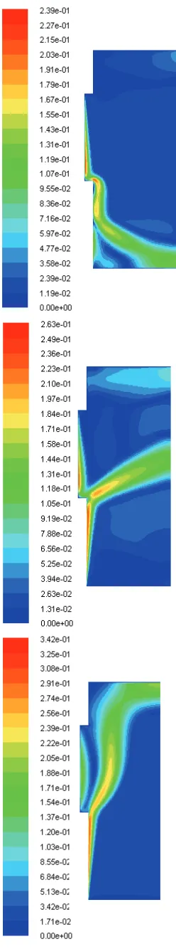
It will be seen from these results that in all cases the Nusselt numbers for the heater are lower than for those for the window and that, as is further illustrated in Fig. 9, at the two lowest values of considered the window Nusselt number variations are essentially identical and the same as that would exist with natural convective flow over a plane vertical isothermal surface. However at the two higher values of the window Nusselt numbers are higher than those for the lower values as a result of the flow of the hot air from the heater near the window. These changes are thus associated with the changes that occur in the flow pattern with increasing at low values of the downward flow from the window dominates whereas at the higher values of the upward flow from the heater predominates. This is illustrated by the typical vertical centre-plane velocity contours for various values of
that are shown in Figs. 10 and 11. The profiles given in Fig. 10 are for a Rayleigh number of 109 whereas those in Fig. 11 are for a Rayleigh number of 1012.
Fig. 9 Variation of window Nusselt number with Rayleigh number for four values of the dimensionless heater temperature,
Now the characteristic velocity associated with a natural convective flow over a vertical plane surface is:
=
r Ra Pr
L
u
(4)where Pr is the Prandtl number and Ra is the Rayleigh number based on the height of the surface, L. The change in flow pattern and the rise in the Nusselt number with that occur with the system being considered here can be expected to occur when the characteristic velocity associated with the upward heater flow becomes comparable to the characteristic downward velocity associated with the window flow, i.e. when:
h Ra Pr Ra Pr
H h
i.e., since:
h Ra Pr Ra Pr
H h
i.e., since:
3/
hRa Ra
H h
the change can be expected to occur when:
3 i.e.,when:
/
1/
H
Ra Ra
H h H
h h
Results are being presented here for the case where H/h = 1 / 0.3 so the change can be expected to occur when:
3.33
Fig. 10 Variation of window Nusselt number with Rayleigh number for
Frontiers in Heat and Mass Transfer (FHMT), 2, 013004 (2011) DOI: 10.5098/hmt.v2.1.3004
Global Digital Central ISSN: 2151-8629
Fig. 12 Variation of window Nusselt number with dimensionless heater temperature, , for Raw = 108
Fig. 13 Variation of window Nusselt number with dimensionless heater temperature, , for Raw = 1011.
This result indicates that for a given system the change in flow pattern will occur at a particular value of irrespective of the value of the Rayleigh number. For the system here being considered it indicates that the change will occur at = 3.33. While this result can only be expected to give a relatively rough description of when the change will occur in the system here being considered because the window is recessed and thus not in the same plane as the heater and because the flow in the system is three-dimensional it should give an indication of when the change from a dominantly downward flow to a dominantly upward occurs and considering the velocity contours shown in Fig. 10 and 11 it will be seen to basically give quite a good description of the conditions when the flow change and hence the significant rise in the window Nusselt number occurs. This is further illustrated by the results given in Figs. 12, 13, and 14. These figures show the variation of window Nusselt number with dimensionless heater temperature, θ, for three values of Rayleigh number. It will be seen that at all Rayleigh numbers considered the window Nusselt number remains essentially constant with increasing up to a value of approximately 1.7 and then increases with increasing Thus for the system here considered the flow pattern change from a dominantly downward flow to a dominantly upward flow occurs at a value of approximately 1.7. The variations of window Nusselt number ratio Nuw / Nuw0, where Nuw0 is the constant
window Nusselt number for values below 1.7, with dimensionless heater temperature, , for six values of the window Rayleigh number is shown in Fig. 15. The mean line through the results for all Rayleigh
Fig. 14 Variation of window Nusselt number with dimensionless heater temperature, , for Raw = 1013
Fig. 15 Variation of window Nusselt number with dimensionless heater temperature, , for various values of Ra. Solid line is mean line through results for greater than 1.7.
numbers for values of 1.7 and higher is also shown in this figure. While an effect of Rayleigh number will be seen to exist in these results this effect is relatively small and the results given in this figure indicate that the Nusselt number ratio variation is the basically the same in laminar and turbulent flows.
3.
CONCLUSIONS
The results of the present study indicate that:1. At the lower values of the dimensionless heater temperature, , considered the downward flow from the window dominates the flow pattern and the variation of the window Nusselt number with Rayleigh number is essentially independent of the value of and approximately the same as for flow over a vertical plane isothermal surface.
2. At the higher values of the dimensionless heater temperature, , considered the upward flow from the heater dominates the flow pattern and the variation of the window Nusselt number with Rayleigh number is dependent of the value of the Nusselt number at a particular value of the Rayleigh number increasing as
increases.
occurs at a fixed value of and the numerical results indicate that the change occurs approximately when:
1.7
4. The basic form of the variation of the ratio of the window Nusselt number to the window Nusselt number at very low values of with is effectively independent of Rayleigh number and thus approximately the same in laminar and turbulent flows, the form of this variation being given in Fig. 15.
ACKNOWLEDGEMENTS
This work was supported by the Natural Sciences and Engineering Research Council of Canada (NSERC) through the Solar Buildings Research Network.
NOMENCLATURE
g Gravitational acceleration (m/s2) B b/HB Distance from bottom of window to floor (m) C c/H
c Distance from top of window to ceiling (m) dr Window recess depth (m)
Dr Dimensionless window recess depth, dr/H
H Height of the window (m) hh Height of heater (m)
Hh Dimensionless height of heater, hh/H
K Thermal conductivity of air (W/m-K) L Height of plane vertical surface (m)
Nuh Mean heater Nusselt number based on hh and on (T’h – TF),
i.e., q'h hh/ k (Th – TF)
Nuw Mean window Nusselt number based on H and on
(Tw – TF), i.e., q'w H/ k (TF – Tw)
Pr Prandtl number
'
q h Mean heat transfer rate from window (W/m2)
'
q w Mean heat transfer rate from window (W/m2)
Raw Rayleigh number based on H and on (TF – Tw)
Rah Rayleigh number based on hh and on (Th – TF)
T Temperature (K)
TF Temperature of air to which window is exposed (K)
Th Temperature of surface of the heater (K)
Tw Temperature of surface of the window (K)
ur Reference velocity
W w / H
Wh wh / H
W Width of window (m) wh Width of heater (m)
Greek Symbols
α Thermal diffusivity (m2/s)
β Bulk expansion coefficient (1/K)
θ (Th – TF) / (Tw – TF)
ν Kinematic viscosity (m2/s)
REFERENCES
Albets-Chico, X., Oliva, A., and Perez-Segarra, C.D., 2008, “Numerical Experiments in Turbulent Natural Convection Using Two-Equation Eddy-Viscosity Models,” J. Heat Transfer, 130(7), 072501-1– 072401-11.
doi:10.1115/1.2907432
Collins, M.R., Harrison, S.J., Naylor, D., and Oosthuizen, P.H., 2002a, “Heat Transfer from an Isothermal Vertical Plate with Adjacent Heated
1072-1077.
doi:10.1115/1.1481357
Collins, M.R., Harrison, S.J., Naylor, D., and Oosthuizen, P.H., 2002b, “Heat Transfer from an Isothermal Vertical Plate with Adjacent Heated Horizontal Louvers: Validation,” J. Heat Transfer, 124(6), 1078-1087. doi:10.1115/1.1481358
Coussirat, M., Guardo, A., Jou, E., Egusquiza, E., Cuerva, E., and Alavedra, P., 2008, “Performance and Influence of Numerical Sub-Models on the CFD Simulation of Free and Forced Convection in Double-Glazed Ventilated Façades,” Energy and Buildings, 40(10), 1781-1789.
doi:10.1016/j.enbuild.2008.03.009
Jurelionis, A., and Edmundas, I., 2008, “CFD Predictions of Indoor Air Movement Induced by Cold Window Surfaces,” J. Civil Engineering and Management, 14(1), 29-38.
doi: 10.3846/1392-3730.2008.14.29-38
Kruger, U., 1996, “Thermal Comfort in the Near-Zone of a Radiator Air Device,” Indoor Air, 6(1), 55-61.
doi:10.1111/j.1600-0668.1996.t01-3-00007.x
Kulkarni, R., and Cooper, P., 1995, “Temperature Distribution and Fuid Flow in an Enclosure with Localized Heating and Cooling,” Int. Comm. Heat Mass Transfer, 22(5), 729-739.
doi:10.1016/0735-1933(95)00059-8
Kuznik, F., Rusaouën, G., and Brau, J., 2007, “Experimental and Numerical Study of a Full Scale Ventilated Enclosure: Comparison of Four Two Equations Closure Turbulence Models,” Building and Environment, 42(3), 1043-1053.
doi:10.1016/j.buildenv.2005.11.024
Lankhorst, A.M., and Hoogendoorn, C.J., 1990, “Numerical Computation of High Rayleigh Number Natural Convection and Prediction of Hot Radiator Induced Room Air Motion,” App. Scientific, 47(4), 301-322.
doi:10.1007/BF00386241
Larson, U., and Moshfegh, B., 2002, “Experimental Investigation of Downdraught from Well-Insulated Windows,” Building and Environment, 37(11), 1073-1082.
doi:10.1016/S0360-1323(01)00110-X
Manz, H., 2003, “Numerical Simulation of Heat Transfer by Natural Convection in Cavities of Façade Elements,” Energy and Buildings, 35(3), 305-311.
doi:10.1016/S0378-7788(02)00088-9
Mohamad, A.A., Sicard, J., and Bennacer, R., 2006, “Natural Convection in Enclosures with Floor Cooling Subjected to a Heated Vertical Wall,” Int. J. Heat Mass Transfer, 49(1-2), 108-121. doi:10.1016/j.ijheatmasstransfer.2005.07.033
Oosthuizen, P.H., 2005, “A Numerical Study of the Effect of a Partially Closed Plane Blind on the Convective Heat Transfer from a Window to a Room”, Chemical Engineering Transactions, 7, Proceedings of 8th
Conference on Process Integration, Modelling and Optimisation for Energy Saving and Pollution Reduction (PRES’05), 2, pp. 633-638. Giardini di Naxos, Italy.
Oosthuizen, P.H., Sun, L., Harrison, S.J., Naylor, D., and Collins, M.R., 2005, “The Effect of Coverings on Heat Transfer from a Window to a Room,” Heat Transfer Engineering, 26(5), 47-65. doi:10.1080/01457630590927345
Frontiers in Heat and Mass Transfer (FHMT), 2, 013004 (2011) DOI: 10.5098/hmt.v2.1.3004
Global Digital Central ISSN: 2151-8629 Exposition, Chicago.
doi:10.1115/IMECE2006-16054
Oosthuizen, P.H., 2006b, “A Numerical Study of the Convective Heat Transfer between a Room and a Window Covered by a Partially Open Plane Blind with a Gap at the Top”, paper no. Advanced Computational Methods in Heat Transfer IX, Proceedings of 9th International
Conference on Advanced Computational Methods in Heat Transfer, Wessex Institute of Technology, New Forest, UK. doi:10.2495/HT060021
Oosthuizen, P.H., 2009, “A Numerical Study of the Development of Turbulent Flow over a Recessed Window-Plane Blind System”, Chemical Engineering Transactions, 18, 69-74, 2009.
doi:10.3303/CET0918009
Oosthuizen, P.H., and Naylor, D., 2009, “A Numerical Study of Laminar-to-Turbulent Transition in the Flow Over a Simple Recessed Window-Plane Blind System”, Proceedings of the 4th Canadian Solar
Buildings Conference, Toronto, Ontario.
Plumb, O. A., and Kennedy, L. A., 1977, “Application of a k-e Turbulence Model to Natural Convection from a Vertical Isothermal Surface,” ASME Journal of Heat Transfer, 99, 79-85.
doi:10.1115/1.3450659
Posner, J.D., Buchanan, C.R., and Dunn-Rankin, D., 2003, “Measurement and Prediction of Indoor Air Flow in a Model Room,” Energy and Buildings, 35(5), 515-526.
doi:10.1016/S0378-7788(02)00163-9
Rohdin, P., and Moshfegh, B., 2007, “Numerical Predictions of Indoor Climate in Large Industrial Premises. A Comparison Between Different k-ε Models Supported by Field Measurements,” Building and Environment 42, 3872-3882.
doi:10.1016/j.buildenv.2006.11.005
Savill, A.M., 1993, “Evaluating Turbulence Model Predictions of Transition. An ERCOFTAC Special Interest Group Project,” Applied Scientific Research, 51(1-2), 555-562.
doi:10.1007/BF01082590
Savin, V.K., 1991, “Energy Conservation in Designing and Analyzing the System ‘Window-Heating Device’,” , Heat and Mass Transfer in Building Materials and Structures, Proceedings of International Centre Heat and Mass Transfer, pp. 717-726.
Schmidt, R.C., and Patankar, S.V., 1991, “Simulating Boundary Layer Transition with Low Reynolds Number k-ε Turbulence Models: Part 1- An Evaluation of Prediction Characteristics,” J. Turbomachinery,
113(1), 10-17. doi:10.1115/1.2927728
Shia-hui, P., and Peterson, F., 1995, “Convection from a cold window with simulated floor heating, by means of a transiently heated flat unit,” Energy and Buildings, 23(2), 95-103.
doi:10.1016/0378-7788(95)00933-7
Sigey, J.K., Gatheri, F.K., and Kinyanjui, M., 2004, “Numerical Study of Free Convection Turbulent Heat Transfer in an Enclosure,” Energy
Conversion and Management, 45, 2571-2582.
doi:10.1016/j.enconman.2003.10.010
Spolek, G.A., 1986, “Airflow in Rooms with Baseboard Heat: Flow Visualization Studies,” ASHRAE Trans., 92(2a), 528-536.
Stamou, A., and Katsiris, I., 2006, “Verification of CFD Model for Indoor Airflow and Heat Transfer,” Building and Environment, 41(9), 1171-1181.
doi:10.1016/j.buildenv.2005.06.029
Turkoglu, H., and Yucel, N., 1995, “Effects of Heater and Cooler Locations on Natural Convection in Square Cavities,” Numerical Heat Transfer, Part A, 27, 351–358.
doi:10.1080/10407789508913705
Xamán, J., Álvarez, G., Lira, L., and Estrada, C., 2005, “Numerical Study of Heat Transfer by Laminar and Turbulent Natural Convection in Tall Cavities of Façade Elements,” Energy and Buildings, 37, 787-794.
doi:10.1016/j.enbuild.2004.11.001
Ye, P., Harrison, S.J., Oosthuizen P.H., and Naylor, D., 1999, “Convective Heat Transfer from a Window with a Venetian Blind: Detailed Modeling”, American Society of Heating, Refrigerating and Air-Conditioning Engineers (ASHRAE) Trans., 105(2), 1-7.
Zhang, Z., Zhang, W., Zhai, Z., and Chen, Q., 2007, “Evaluation of Various Turbulence Models in Predicting Airflow and Turbulence in Enclosed Environments by CFD: Part 2-Comparison with Experimental Data from Literature,” ASME HVAC & R Research, 13(6), 871-886. Zheng, X., Liu, C., Liu, F., and Yang, C.-I., 1998, “Turbulent Transition Simulation Using the k-ω Model,” International Journal for Numerical Methods in Engineering, 42(5), 907-926.