Please cite this article as: B. Pordel Maragheh, A. Jalali, S. Mohammad Mirhosseini, Effect of the Initial Local Failure Type on Steel Braced Frame Buildings against Progressive Collapse, Journal of Engineering (IJE), IJE TRANSACTIONS A: Basics Vol. 33, No. 1, (January 2020) 34-46
International Journal of Engineering
J o u r n a l H o m e p a g e : w w w . i j e . i rEffect of Initial Local Failure Type on Steel Braced Frame Buildings against
Progressive Collapse
B. Pordel Maragheha, A. Jalali*b, S. M. Mirhosseini Hezaveha
a Department of Civil Engineering, Arak Branch, Islamic Azad University, Arak, Iran b Faculty of Civil Engineering, University of Tabriz, Tabriz, Iran
P A P E R I N F O
Paper history:
Received 22 March 2019
Received in revised form 23 September 2019 Accepted 07 November 2019
Keywords:
Progressive Collapse Finite Element Method Alternate Load Path Method Braced Steel Buildings Blast
Fire
A B S T R A C T
In many studies, the alternative load path method (APM) has been used for progressive collapse analysis. In this method, one or several columns of the building are removed and the building response is investigated. This method ignores the initial local failure cause of building and this can affect the structural response. Investigation of ignoring the initial local failure cause of steel braced frames is the main purpose of this research. The variables include the type of progressive collapse investigation (ignoring the initial cause of failure or APM, considering blast loading and the heat caused by the fire as the initial causes of failure) and the location of the initial local failure in plan (outer and inner frame) and in floors (1st, 2nd and 3rd). 4-story braced steel buildings were simulated using ABAQUS software and the responses were compared using different methods. The most important results showed that the axial forces are very noticeable in the columns around the damaged site if the initial local failure caused by explosive loading; while these forces are ignored when APM is used. Therefore, due to this significant difference, if the design of a steel building is to be considered against progressive collapse, it is recommended to consider the initial local failure in order to make the appropriate design in accordance with it. Therefore, the initial loading type has a very significant effect on the structure response, and ignoring the initial local failure can lead to incorrect predictions of the structure response.
doi: 10.5829/ije.2020.33.01a.05
1. INTRODUCTION 1
According to the American Society of Civil Engineers (ASCE), progressive collapse occurs when an initial failure spreads in a structure from one element to another, eventually leading to the collapse of a total structure or a main part of it [1]. The reasons that can lead to progressive collapse can be vehicle impact, gas explosion, aircraft accidents, construction errors, fire load, blast events and etc. Most of these events have a short duration of impact which leads to structural dynamic response.In traditional structural design codes, the progressive collapse was considered indirectly with the definition of importance degree for structures; but recently, regulations have been developed about the progressive collapse of structures. The most acceptable of these regulations is Unified Facilities Criteria (UFC)
*Corresponding Author Email: [email protected] (A. Jalali)
investigated. For this purpose, the finite element method (FEM) is used with ABAQUS [6] software.
In recent years, there have been many studies on progressive collapse and each of them has examined part of this event. Almusallam et al. [7] investigated the precast concrete beam-column joints against progressive collapse. The results showed that the joints have a considerable impact on the response of the structures against progressive collapse. Gao and Guo [8] investigated a 20-story building against progressive collapse and the effect of composite floor was evaluated. The results showed that the overall behavior of the structure depends on the position of the column removal. Gernay and Gamba [9] examined the progressive collapse caused by the fire. The results showed that fire-induced heat has a significant influence on the structural response against progressive collapse. Li et al. [10] studied the behavior of steel frames against progressive collapse. ABAQUS software was used for this purpose. The results showed that the type of steel frame (for example, weak beam strong-column or vice versa) and the location of column removal has important role on the strength of the steel frame against progressive collapse. Lou et al. [11] investigated the behavior of portal frames against progressive collapse caused by fire. The results showed that corner and outer columns have an important role in preventing the spread of collapse to adjacent buildings. Zhu et al. [12] investigated the progressive collapse of semi-rigid steel frames. Finally, an equation presented for the dynamic increase factor. This equation is a function of the energy demand and energy capacity ratio. Tavakoli and Kiakojoori [13] presented a new method for simulating the dynamic removal of columns in steel frames. They evaluated the structural response of a five-story steel building using this method in various column removing steps. The nonlinear effects of materials were also considered. The results indicated that the potential of progressive collapse is essentially dependent on the column removal position. Kaafi and Ghodrati Amiri [14] simulated a 5-story steel building with and without considering slab using ABAQUS software and the potential of progressive collapse was evaluated. The results showed that the lack of considering the slab during computation can leads to errors in evaluating the potential of progressive collapse in the structure. Elshaer et al. [15] evaluated the progressive collapse of multistory structures under the earthquake. The nonlinear dynamical analysis was performed and various parameters such as position of column removal were investigated.The results showed that removing the edge columns creates a more critical state than the corner columns. Hosseini and Ghodrati Amiri [16] investigated the potential of progressive collapse in steel frames with buckling restrained eccentric braces. For this purpose, APM was used and 7 buildings with
five-story were evaluated in different columns removal scenarios. The results showed that removing the corners columns leads to more critical responses in structures with ordinary and eccentric buckling restrained braces. Faghihmaleki et al. [17] evaluated progressive collapse in steel frames with different braces. To study the progressive collapse of structures against earthquake, three steel moment frame buildings with 8-story and concentric, eccentric and buckling restrained braces were selected. Several structural members removed and the effect of these scenarios on the dynamic behavior of structures during the earthquake was investigated. The potential and capacity of buildings for progressive seismic collapse and the failure modes were determined using incremental dynamic analysis. Pourasil et al. [18] proposed a procedure to evaluate the progressive collapse of blast loading in steel structures with moment frames. For this purpose, a 7-story steel building was simulated under blast loading, and the pressures equivalent to blast load were applied in four different states to structural members near the blast. The results showed that the potential of progressive collapse during considering blast loading as the cause of failure will be different compared to common methods used for investigating the progressive collapse.
In most of these studies, a number of structural columns were removed under different conditions and the structural response was evaluated under new conditions (the lack of a number of columns). The APM without considering the load type is relatively simple but it has less accurate and it doesn't seem to have reliable predictions. In general, the defect of APM is regardless of initial failure or damage of adjacent structural members due to the blast or fire load. According to the defect of APM, the used method in this study may predict more reliable predictions of progressive collapse caused by blast and fire loads. So that, more realistic responses will be investigated by considering the initial failure .In other words, the most important purpose of the present study is to compare three different methods for the analysis of braced steel buildings against progressive collapse. In the first method, the blast load is applied directly to the structure. In the second method, the initial cause of fire collapse is heat caused by fire and in the third method, the direct column removal method (APM) is used.
2.STUDY PROCEDURE
respectively. The lateral force resisting system in both directions is a simple frame with concentric diagonal braces.In the next step, ABAQUS software [6] is used to analyze four-story steel frames against the progressive collapse potential due to explosive loading and the load caused by fire. 3D finite element models of frames are simulated and the structure response is compared with each other in three types of loading conditions (Blast, Fire, and APM); so that the impact of loading type on the evaluation of progressive collapse can be examined in final behavior of frames. The studied modes are presented in Table 1. The variables in the present study include the type of initial loading (regardless of the initial cause of failure, blast loading and the heat caused by the fire), the location of the initial local failure in plan (outer and inner frame) and floors (1st, 2nd, and 3rd).
TABLE 1. Variables
Contraction Initial local
failure type (Method of investigation) Initial local failure
location of columns Case Story Frame location Without Removal Blast ---- ---- 1 St1–I–B First Inner 2 St2–I–B Second Inner 3 St3–I–B Third Inner 4 St1–O–B First Outer 5 St1–I–F Fire First Inner 6 St2–I–F Second Inner 7 St3–I–F Third Inner 8 St1–O–F First Outer 9 St2–O–F Second Outer 10 St3–O–F Third Outer 11 St1–I–APM Column removal (APM) First Inner 12 St2–I–APM Second Inner 13 St3–I–APM Third Inner 14 St1–O–APM First Outer 15 St2–O–APM Second Outer 16 St3–O–APM Third Outer 17
I: Inner frame
O: Outer frame
B: Blast load
F: Fire load
Without Remove: Without column removal
St1: Column removal at first story
St2: Column removal at second story
St3: Column removal at third story
APM: Alternative load path method
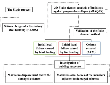
The sections are designed in a way that the stress ratios are as close as possible to each other so that different modes can be compared correctly. The studied building is residential and the earthquake loads were obtained with the assumption that the building is located in seismic zone 4 of Iran. The structural design results are presented in Table 2. Details of the used sections are also shown in Table 3. It should be noted that the design is done in several steps, on one hand, the selection of sections is close to optimal mode and on other hand, the design of components is simple and uniform. The general process of the study is shown in Figure 1.
3. FINITE ELEMENT SIMULATION
Elements of the structures in this study include beams, columns, and braces. These elements are 3D and deformable.The characteristics of the used materials in this study are steel and concrete. Beam elements were used to model the beams, columns, and braces. These elements are 3D and deformable. Concrete damage plasticity model was used to define concrete. This
TABLE 2. Design results
Brace Column Beam Story Box 200x200x20 2IPE 300 Box 350×350×20 First Box 200x200x20 2IPE 300 Box 350×350×20 Second Box 200x200x20 2IPE 270 Box 300×300×20 Third Box 200x200x20 2IPE 270 Box 300×300×20 Fourth
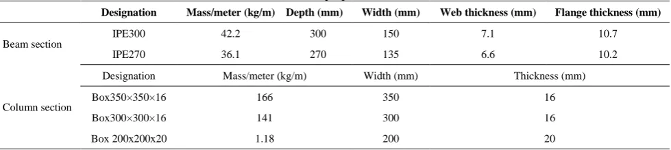
TABLE 3. Geometric properties of the sections
Designation Mass/meter (kg/m) Depth (mm) Width (mm) Web thickness (mm) Flange thickness (mm)
Beam section IPE300 42.2 300 150 7.1 10.7
IPE270 36.1 270 135 6.6 10.2
Column section
Designation Mass/meter (kg/m) Width (mm) Thickness (mm)
Box350×350×16 166 350 16
Box300×300×16 141 300 16
Figure 1. Study process flowchart
model considers two main assumptions in the failure mechanism, which includes tensile cracking and compression crushing. Dynamic explicit analysis was used to analyze the models. This analysis is explicitly used to design large scale models with short dynamic response durations and for processes with high discontinuities. This type of analysis allows us to use large deformations theory.Tie constraint has been used to define the interaction between members. This allows the user to combine two surfaces that their meshing is different from each other. In order to determine the optimal meshing in modeling, examine the convergence response method was used. The proposed meshing is reliable enough to ensure that the applied forces were accurately calculated. The imposed loads on building include the weight of structural elements (beam, column, floor, and brace), dead and live loads on the floor of structure. Three different methods were used to investigate the progressive collapse:
3. 1. Alternative Load Path Method APM analysis is a sophisticated analysis method that can be used to determine the potential for progressive collapse in a given facility. The applied loads to studied models are included [2, 3]:
1. Increased gravity loads for the floor above removed column : This load combination should be affected by gravity loads on the adjacent spans of removed elements at all top floors of these elements.
(0.9or1.2)D (0.5Lor0.2S)
GLD=LD + (1)
where, GLD is increased gravity loads for deformation
controlled actions in linear static method, D is dead load including facade load and L is live load including live load reduction factor [1] and S is snow load and ΩLD is
load increased factor for deformation controlled actions in linear static method.
2. Gravity loads for floor areas away from the removed column :
This load combination should be affected on spans that are not loaded with GLD.
(0.9or1.2)D (0.5Lor0.2S)
GLD= + (2)
where, G is gravity load. Loads and load locations for external and internal column removal according to UFC is shown in Figure 2. Also Locations of removed columns in this study for APM is shown in Figure 3.
Column removal modes of APM were investigated in six modes in the first, second and third story of inner and outer frames, respectively. In the dynamic analysis of progressive collapse, both the UFC [2] and GSA [3] regulations do not recommend the use of dynamic load increase factor. For nonlinear dynamic analysis, the axial reaction of the column is calculated before the removal and then, during the process of removing the columns, these concentrated axial forces must be replaced with removed columns. Figure 4 shows the gravity loads and the supported reaction of removed columns. This loading pattern is in accordance with the UFC Code [2].
3. 2. Blast Loading Numerical simulation of buildings against the explosion is done using ABAQUS Software. Simulation of explosion was carried out on models using the CONWEP option. This is an experimental model of Kingery and Bulmash [20], and is the result of many explosive tests on a wide range of explosive charges. The considered blast was an airblast type. The explosive loading intensity applied to the building is equivalent to 500 kilograms of TNT and is 6 meters from the explosion center. For this purpose, according to Hopkinson-Cranz law [21, 22], by determining the scaled distance (Z) from Equations (3) to (5), the overpressure generated by the explosion can be calculated.
3 1
W R
Z= (3)
a b
Figure 3. Locations of removed columns in this study (APM) a: Outer frame b: Inner frame
Figure 4. Column reaction and applied loads according to UFC [2]
) ( log10 Z
X= (4)
log
1319 0.2331 0.4644 )(
log 2
10
10 Z Ps =− X − X+ (5)
where, R is the distance from the detonation source to the point of interest (m) and W is the weight (more precisely: the mass) of the explosive (kg). The Friedlander explosive load equation is used in this study. This equation is one of the most accurate and complete numerical solutions for the explosion wave (Equations (6) and (7)). Where, pr,max is the maximum
overpressure, td is the positive phase duration and b is a
decay coefficient of the waveform [23]. These parameters are shown in Figure 5. The position of explosive charge of the outer and inner frame is shown in Figure 6.
d t bt d r r e t t p r p − − = 1 )
( ,max (6)
5 . 0 2 2 2 2 0 max 35 . 1 1 32 . 0 1 048 . 0 1 5 . 4 1 808 + + + + = Z Z Z Z p
pr (7)
3. 3. Fire Loading Fire is applied to the column after applying axial loads. It is necessary to select and apply a fire curve to simulate the effect of fire on the
Figure 5. The ideal blast wave,s pressure-time history [18, 22]
a b
structure. The fire curve is a temperature-time curve that shows the gradual change of temperature over time to indicate the environment in which the structure is located.
The ISO 834 fire curve [24] was used to apply fire to the members (Equation (8)). Fire curve refers to changes in temperature and heat caused by local fire to adjacent members of the column removal location in accordance with ISO834 is shown in Figure 7. The position of the damaged columns in the fire is shown in Figure 8.
(
)
010 8t 1 T
Log
T= + + (8)
Figure 7. ISO834 Temperature-Time curve caused by local fire [23]
a b
Figure 8. The position of initial failure caused by fire loading a:Outer frame b: Inner frame
4. VALIDATION
Three different experimental studies are utilized in order to validate the FEM used in the modeling of APM (loss of column), blast and fire loading. The accuracy of the used method to simulate the behavior of APM is investigated using Guo et al. [25]. The studied frame was a one story composite frame with four spans, which was built with a 1/3 scale in the laboratory (Figure 9). The length of the frame spans is 2 meters and its height is 1.20 meters. The beam section is H200×100×5.5×8 and the cross-section of the columns is H200× 200×8×12. The depth and width of the slabs are 100 and 80 mm, respectively. The reinforcement mesh ratio for
RC slab was considered 0.85%.In order to simulate the column removal, the middle column was not supported. Material properties are shown in Table 4.
The behavior of the frame, as well as the concrete slab during the test, were evaluated. The static vertical load was applied at the top of the middle column.More information about the material and the details of the test can be found in Guo et al study [25]. The frame investigated in Guo et al. [25] test is simulated using the FEM used in the present study (Figure 9). Load-displacement values of the frame made in Guo et al. test and the simulated finite element model are compared in Figure 10. As it is seen, the force and deformation values corresponding to the experimental and numerical samples are in good agreement.
Figure 11 shows comparison of load-displacement curves of simulation and experimental results. The second validation of the FEM in modeling of blast loading on steel members is performed using Lawver et al. [26] study. In the mentioned study, seven steel columns were exposed to the different amount of
TABLE 4. Material properties [25]
Section fy (MPa) Fu (MPa) Es (105MPa)
Beam
Flange 269 401 1.96 Web 275 411 2.09
Column Flange 247 396 2.00 Web 276 415 1.98
Reinforcement 8T 325 487 - 12T 331 464 1.95
Figure 9. Vertical displacement of the tested frame in the laboratory [27]
Figure 11. Comparison of load-displacement curves of simulation and experiment
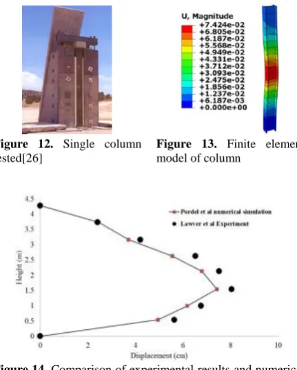
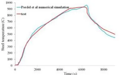
explosive loads and only the details of the column with a cross-section of W360×122, which was exposed to a close explosion loading, were presented. The height of the column was 4.30. The mentioned column was loaded simultaneously with an axial load of 670 N and a blast load in the lateral direction. The column is connected to a concrete foundation through a baseplate and 8 bolts. The column was instrumented with accelerometers and pressure transducer. An overview of the experimental test and numerical model is presented in Figures 12 and 13. Also, the comparative graph of the lateral displacement of experimental results and numerical simulation is presented in Figure 14. The simulation results showed a good agreement with experimental results.
Figure 12. Single column tested[26]
Figure 13. Finite element model of column
Figure 14. Comparison of experimental results and numerical simulation
Also, the effect of fire loading on the steel building response is one of the most important purposes of the present study; therefore, in order to validate the used method in simulating fire loading, an experimental study that was performed by Jiang et al. [27] is used. As it was shown in Figure 15, the tested frames had two stories and four spans. The lengths of central and side spans were 2.2m and 2m, respectively. The height of the first and second story was 1.3 and 1.2 meters, respectively. The dimensions of the steel members with tubular rectangular sections for columns and beams are 30×3×50 cm and 40×60×60 cm, respectively. The central column located on the first floor was heated by an electric furnace. The initial axial force of the heated column was between 9.8 kN, 14.0 kN and 20.9 kN for Frames 1, 2 and 3, respectively. Plastic strain due to fire in the center column of Frame 1 is shown in Figure 16. During the tests, parameters such as temperatures, displacements, and strains were measured. Before turning off the furnace and cooling down the column, the furnace gas temperature increased to 950, 829 and 735°C for Frames 1, 2 and 3, respectively. The temperatures measured in the section of heated columns were almost the same. Further information of the tests is presented in Re [28]. The model is established by the same modeling techniques mentioned in this paper. Comparison of measured and computed temperatures in the heated column is presented in Figure 17. The predicted temperature by the model is in good agreement with the experimental result.
Figure 15. Deformations of test frame after unloading [27]
Figure 17. Comparison of measured and computed temperatures in the heated column
5. ANALYTICAL RESULTS
In this section, the results have been analyzed. For this purpose, the displacement of the column removal area, the axial force values of the columns adjacent to the column removal location, and the values of the angle of rotation of the beam to the column are compared in different states. For this purpose, the displacement of the columns that were subjected to initial failure and the axial forces of the columns adjacent to the location of the initial local failure are compared.
Without Removal
St1–I–B
St2–I–B
St3–I–B
St1–O–B
St1–I–F
St2–I–F
St1–O–F
St2–O–F
St3–O–F
St1–I–APM
St2–I–APM
St3–I–APM
St1–O–APM
St2–O–APM
St3–O–APM
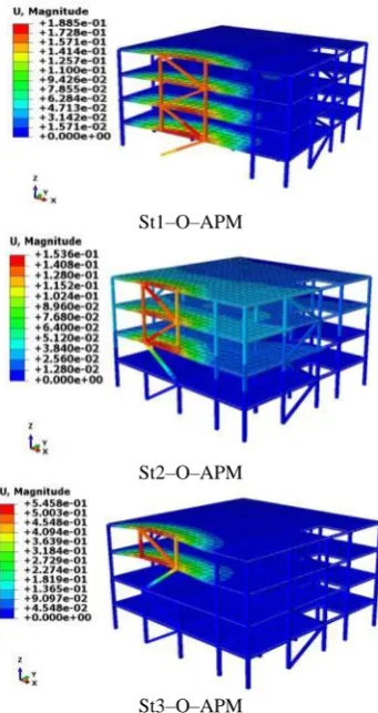
Figure 18. The deformable shape of buildings in different modes
The deformable shape of buildings and the displacement values created at the location of the damaged columns is shown in Figure 18 (in meter). As mentioned, the studied variables include the type of progressive collapse investigation (ignoring the initial cause of failure or APM, considering blast loading and the heat caused by the fire as the initial causes of failure) and the location of the initial local failure in plan (outer and inner frame) and in floors (1st, 2nd and 3rd). Based on this, it has been tried to evaluate the effectiveness of the
studied parameters on the damaged columns
displacement.
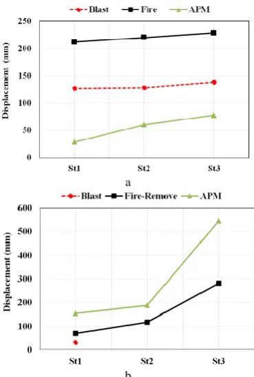
applied to the columns and their adjacent structural members located on the inner frame, the maximum displacement of damaged columns in the first, second and third floors is 66, 71 and 65 percent higher than the corresponding values in APM, respectively. According to mentioned values, it can be concluded that in the APM, which the initial failure does not consider, the maximum displacement of damaged columns in the inner frame is not correctly estimated. So that the displacement values obtained by the APM have a significant difference with the displacement values obtained from other methods. Despite the fact that the maximum displacement of damaged columns located in the outer frame is completely different from the corresponding values in the inner frame and the APM exhibits more displacement compared to the blast and fire loading methods. So, it can be stated that depending on the position of the damaged column in the internal and external frames, the initial cause of failure in structure can create different responses.
On the other hand, according to Figure 20, it can be seen that in all three methods, causing damage in the columns located on the upper floors leads to more displacement. In other words, removing the columns and causing local damage on the upper floors is much more dangerous and can make the behavior of the structure more critical.
a
b
Figure 19. Maximum values of displacement generated at the damaged columns in different modes with the aim of examining the used method in progressive collapse analysis and the damaged column location a: Inner frame b: Outer frame
In Figure 20 maximum displacement of damaged columns is compared with the aim of examining the position of them in outer and inner frames. By considering explosion and fire as the initial cause of failure, the displacement of the damaged members placed in the inner frame in most cases is greater than the corresponding values of the outer frame. This is while the maximum displacement of the removed columns in the outer frame is much greater than the displacement of the columns removed in the interior frame when APM is used. So it can be concluded that the assumptions of each three used methods in the present study to predict the behavior of the structure against progressive collapse can provide different responses. As the APM states that the column removal in the outer frames creates more displacements; this is while applying fire and explosion as the initial local damages in the internal frame creates more displacements.
a
b
c
One of the proposed criteria in the progressive collapse analysis is the force criterion that has been evaluated in this section. After removing the columns in different modes, the load is distributed across the adjacent members, and these members must have the ability to withstand excessive force [14]. For this purpose, the force redistribution of members can be seen using distributing axial forces of the columns adjacent to the removal site before and after removing columns.
In Figure 21 maximum axial forces of columns adjacent to damaged columns are compared with the aim of examining the used method in the progressive collapse analysis and the position of the damaged columns in the floors;As it is seen, when the explosion load affects the two columns and their adjacent members in inner frame the axial forces of the adjacent damaged columns are more than the corresponding values in APM and fire loading.
According to Figure 22, applying the blast load to the columns in the inner frame has led to increase the maximum axial force around the initial local failure to 317, 318, and 230 percentages in the first, second and third floors, respectively. However, in the APM, removing two columns in the inner frame has led to increase the maximum axial force around column removal site to 15, 25, and 58 percentages in the first, second and third floors, respectively.Comparison of the axial force values obtained from the three methods used indicates that if the initial failure reason is explosive loading, the axial forces of columns around the removal site are very noticeable; which these forces are ignored in APM.Therefore, due to this significant difference, it is recommended to be considered the initial cause of failure during progressive collapse analysis of steel braced frame buildings; thereby building designing against progressive collapse will be accordance with the initial cause of failure. Since force transferring of the remaining structural members that have been affected by the local failure can certainly prevent progressive collapse, and if the correct prediction of failure is not initialized, the structure response against progressive collapse potential will not be appropriate.On the other
a
b
Figure 21. Maximum values of axial forces generated at the damaged columns in different modes with the aim of examining the used method in progressive collapse analysis and the damaged column location a: Inner frame b: Outer frame
Figure 22. Percentage of axial force increase in the columns around the location of the local failure
hand, it is observed that applying the heat-induced by fire to the inner columns and their adjacent members of frames has caused more axial forces in the columns around the studied area compared to APM (column removal).
6. CONCLUSIONS
was observed. The most important results showed that in the APM, which the initial failure does not consider, the maximum displacement of damaged columns in the inner frame is not correctly estimated. So that the displacement values obtained by the APM have a significant difference with the displacement values obtained from other methods. On the other hand, it can be stated that depending on the position of the damaged column in the internal and external frames, the initial reason for local failure in structure can create different responses.
Also, comparison of the axial force values obtained from the three methods used indicates that if the initial failure reason is explosive loading, the axial forces of columns around the removal site are very noticeable; which these forces are ignored in APM. Therefore, due to this significant difference, it is recommended to be considered the initial reason of failure during progressive collapse analysis of steel braced frame buildings; thereby building designing against progressive collapse is accordance with the initial reason of failure. damages in the internal frame creates more displacements.
7. REFERENCES
1. Institute, S.E., "Minimum design loads for buildings and other structures, Amer Society of Civil Engineers, Vol. 7, (2006). 2. DoD, "Design of buildings to resist progressive collapse",
Unified Facilities Criteria (UFC) 4-023-03, (2009).
3. Gsa, U., "Progressive collapse analysis and design guidelines for new federal office buildings and major modernization projects", Washington, DC, (2003).
4. Astaneh-Asl, A., Jones, B., Zhao, Y. and Hwa, R., "Progressive collapse resistance of steel building floors", Report Number UCB/CEE-Steel-2001, Vol. 3, (2001).
5. Bagheripourasil, M. and Mohammadi, Y., "Comparison between alternative load path method and a direct applying blast loading method in assessment of the progressive collapse", Journal of
Rehabilitation in Civil Engineering, Vol. 3, No. 2, (2015),
1-15.
6. Hibbitt, H., Karlsson, B. and Sorensen, P., "Abaqus analysis user’s manual version 2016", Dassault Systèmes Simulia Corp, Providence, (2016).
7. Almusallam, T.H., Elsanadedy, H.M., Al-Salloum, Y.A., Siddiqui, N.A. and Iqbal, R.A., "Experimental investigation on vulnerability of precast rc beam-column joints to progressive collapse", KSCE Journal of Civil Engineering, Vol. 22, No. 10, (2018), 3995-4010.
8. Gao, S. and Guo, L., "Progressive collapse analysis of 20-storey building considering composite action of floor slab",
International Journal of Steel Structures, Vol. 15, No. 2,
(2015), 447-458.
9. Gernay, T. and Gamba, A., "Progressive collapse triggered by fire induced column loss: Detrimental effect of thermal forces",
Engineering Structures, Vol. 172, (2018), 483-496.
10. Li, L.-L., Li, G.-Q., Jiang, B. and Lu, Y., "Analysis of robustness of steel frames against progressive collapse", Journal
of Constructional Steel Research, Vol. 143, (2018), 264-278.
11. Lou, G., Wang, C., Jiang, J., Jiang, Y., Wang, L. and Li, G.-Q., "Fire tests on full-scale steel portal frames against progressive collapse", Journal of Constructional Steel Research, Vol. 145, (2018), 137-152.
12. Zhu, Y.F., Chen, C.H., Yao, Y., Keer, L.M. and Huang, Y., "Dynamic increase factor for progressive collapse analysis of semi-rigid steel frames", Steel and Composite Structures, Vol. 28, No. 2, (2018), 209-221.
13. Tavakoli, H. and Kiakojouri, F., "Numerical study of progressive collapse in framed structures: A new approach for dynamic column removal", International Journal of Engineering,
Transactions A: Basics, Vol. 26, No. 7, (2013), 685-692.
14. Kaafi, P. and Ghodrati Amiri, G., "Investigation of the progressive collapse potential in steel buildings with composite floor system", in World Academy of Science, Engineering and Technology, International Journal of Civil and Environmental Engineering, Vancouver, Canada. Vol. 8, (2014), 1-8.
15. Elshaer, A., Mostafa, H. and Salem, H., "Progressive collapse assessment of multistory reinforced concrete structures subjected to seismic actions", KSCE Journal of Civil Engineering, Vol. 21, No. 1, (2017), 184-194.
16. Hosseini, S.M. and Amiri, G.G., "Successive collapse potential of eccentric braced frames in comparison with buckling-restrained braces in eccentric configurations", International
Journal of Steel Structures, Vol. 17, No. 2, (2017), 481-489.
17. Faghihmaleki, H., Nejati, F., Zarkandy, S. and Masoumi, H., "Evaluation of progressive collapse in steel moment frame with different braces", Jordan Journal of Civil Engineering, Vol. 11, No. 2, (2017), 290-298.
18. Pourasil, M.B., Mohammadi, Y. and Gholizad, A., "A proposed procedure for progressive collapse analysis of common steel building structures to blast loading", KSCE Journal of Civil
Engineering, Vol. 21, No. 6, (2017), 2186-2194.
19. CSI, C., "Analysis reference manual for sap2000, etabs, safe and csibridge", Computers and Structures, Inc., Berkeley, CA, USA, (2015).
20. Kingery, C.N. and Bulmash, G., "Airblast parameters from tnt spherical air burst and hemispherical surface burst, US Army Armament and Development Center, Ballistic Research Laboratory, (1984).
21. Hopkinson, B., "British ordnance board minutes 13565", The National Archives, Kew, UK, Vol. 11, (1915).
22. Granz, C., Lehrbuch der ballistik. 1: Aussere ballistik. Berlin, j. 1925, Springer.
23. Larcher, M., "Pressure-time functions for the description of air blast waves", Joint Research Centre, Technical Notes. (2008), 46829.
24. ISO, I., "834: Fire resistance tests-elements of building construction", International Organization for Standardization, Geneva, Switzerland, (1999).
25. Guo, L., Gao, S., Fu, F. and Wang, Y., "Experimental study and numerical analysis of progressive collapse resistance of composite frames", Journal of Constructional Steel Research, Vol. 89, (2013), 236-251.
26. Lawver, D., Daddazio, R., Vaughan, D., Stanley, M. and Levine, H., "Response of aisc steel column sections to blast loading", in ASME 2003 Pressure Vessels and Piping Conference, American Society of Mechanical Engineers Digital Collection. (2003), 139-148.
27. Jiang, B., Li, G.-Q., Li, L. and Izzuddin, B., "Experimental studies on progressive collapse resistance of steel moment frames under localized furnace loading", Journal of Structural
Effect of Initial Local Failure Type on Steel Braced Frame Buildings against
Progressive Collapse
B. Pordel Maragheha, A. Jalalib, S. M. Mirhosseini Hezaveha
a Department of Civil Engineering, Arak Branch, Islamic Azad University, Arak, Iran b Faculty of Civil Engineering, University of Tabriz, Tabriz, Iran
P A P E R I N F O
Paper history:
Received 22 March 2019
Received in revised form 23 September 2019 Accepted 07 November 2019
Keywords:
Progressive Collapse Finite Element Method Alternate Load Path Method Braced Steel Buildings Blast
Fire
دیکچ ه
تاعلاطم زا یرایسب رد ،
یم هدافتسا هدنور شیپ یبارخ لیلحت یارب نیزگیاج راب ریسم شور زا ای کی شور نیا رد .دوش
دنچ نوتس زا یم فذح نامتخاس یم رارق یبایزرا دروم نامتخاس خساپ و دنوش
رد یبارخ داجیا هیلوا لماع شور نیا .دریگ
ر هزاس یم هدیدان ا یم عوضوم نیا و دریگ .دهد رارق ریثات تحت ار هزاس خساپ دناوت
سررب ی سم شور ری اجراب نیزگی رد دان هدی لوا لماع نتفرگ هی ی ا داجی بارخ ی پ شی اه باق رد هدنور ی دلاوف ی دنبراهم ی هدش مهم ناونع هب هعلاطم فده نیرت
یم رضاح .دشاب غتم یاهری سررب دروم ی ترت هب بی لماش راذگراب عون ی عضوم ی لوا هی لوا تلع نتفرگ رظن رد نودب( هی بارخ ،ی راذگراب ی شان ترارح و راجفنا ی
زوس شتآ زا ی
عقوم ،) تی نلاپ رد هیلوا یعضوم یبارخ داجیا ب باق( ینوری و لخاد ی و ) تاقبط( تاقبط رد 1 ، 2 و 3 ) م ی شاب ن د نامتخاس . یاه دلاوف ی دنبراهم ی هدش 4 ن زا هدافتسا اب هقبط رازفا مر ABAQUS بش هی زاس ی دندش شور زا هدافتسا اب خساپ و اه ی اب فلتخم رگیدکی اقم هسی دش . رت مهم نی اتن جی لصاح م ناشن ی تروص رد دهد هکی ا لماع داجی بارخ ی عضوم ی لوا هی راذگراب ی راجفنا ی ن ،دشاب یاهوری روحم ی سب رای گمشچ یری نوتس رد اه ی م دوجو هب فذح لحم فارطا ی آ ؛دی هک ا نی ن ی شور زا هدافتسا ماگنه رد اهور
APM دان هدی م هتفرگ ی دوش . ا زا نی ا هب هجوت اب و ور نی گمشچ توافت ری صوت هی م ی دوش حارط هچنانچ ی کی نامتخاس دلاوف ی دنبراهم ی ربارب رد هدش
بارخ ی پ شی لوا لماع ،دشاب رظن دروم هدنور هی
بارخ ی رط ،لماع نآ اب بسانتم ات دوش هتفرگ رظن رد حا ی یاه تروص مزلا ذپ ؛دری ز اری ن لاقتنا ًاملسم وری اضعا طسوت ی هزاس ا ی قاب هدنامی نامتخاس ی بارخ راچد هک ی
عضوم ی م ،تسا هدش ی دناوت زا بارخ ی پ شی گولج هدنور یری امن دی پ هچنانچ و شی ینیب تسرد ی بارخ زا ی لوا هی بارخ ربارب رد هزاس خساپ ،دوشن ی یاه لامتحا ی ن زی دهاوخن بسانم .دوب نیاربانب م ی ناوت ب نای راذگراب عون هک دومن ی لوا هی سب شقن رای ثات ری راذگ ی هزاس خساپ رب
بارخ نتفرگ رظن رد مدع و دراد ی لوا هی م ی دناوت پ رجنم شی ینیب یاه تسردان ی .دوش هزاس خساپ زا
![Figure 5. The ideal blast wave,s pressure-time history [18, 22]](https://thumb-us.123doks.com/thumbv2/123dok_us/14235.2001357/5.595.61.275.604.722/figure-ideal-blast-wave-s-pressure-time-history.webp)
![Figure 7. ISO834 Temperature-Time curve caused by local fire [23]](https://thumb-us.123doks.com/thumbv2/123dok_us/14235.2001357/6.595.59.285.460.533/figure-iso-temperature-time-curve-caused-local-fire.webp)