and optimal control
B
.
Sepehri1, A.
Hemati21- Assistant Professor2- MSc Student, Islamic Azad University of Khorramabad, Iran. *[email protected]
Abstract
In this paper, the 1/4 vehicle model have been simulated. The vehicle body acceleration using optimal control has been optimized. The vehicle ride comfort is achieved by using robust control, and it has been compared with optimal control. The active suspension can help the vehicle to have a good dynamic behavioral. In this paper, two degrees of freedom dynamic vibration model of a general vehicle is developed through the designation of a closed-loop and robust control system. Irregular road input is simulated as sinusoidal signals, and the vehicle vibration response is optimized. Using robust control the vehicle ride comfort has been improved, and using optimal control not only the ride comfort has been achieved, also the vehicle acceleration is optimized.
Keywords: Optimal control, Robust control, 1/4 vehicle model, Ride comfort
1. Introduction
The vehicle vibration is a problem for passengers and drivers so many company and researchers are looking for a new manner to achieve ride comfort. Controller systems can help to improve vehicle ride comfort. On the other hand vibration intensity is also of major importance which has a direct relation with forward speed of the vehicle; so often an increase of speed is unbearable. That is why the operators feel discomfort in driving the larger tractors at high speed and full nominal power [1]. Recently, passive vehicle suspension with regard to affective factors on system parameters such as; spring constant coefficients and damping coefficients, as well as the external force, have attracted a lot of researcher attentions. Thus far, different methods have been used to control 1/4 body vibration [2]. [3] Present the design and performance of a vibration isolation and suppression system using a novel hybrid actuator concept to provide both passive isolation and active damping. According to [4] the particular on-road usage of SUV’s makes these vehicles more prone to accidents. [5] Proposed a vibration isolation system using a conventional spring connected in parallel with a fully passive, negative-stiffness-mechanism to produce a reduced value of the supporting stiffness. The design of an adaptive active suspension system, in order to simultaneously improve ride comfort and travel suspension under
various traffic conditions, is addressed in [6]. Guclu has been presented a vibration control performance of a seat suspension system of non-linear full vehicle model using fuzzy logic controller [7]. Vibration control performance of a semi-active electro rheological seat suspension system using a robust sliding mode controller has been searched by Huang and Chen [8]. The control system automatically switches between “ride comfort” and “handling” modes of evaluating several vehicle parameters. Ride height control is also built into the system to level the vehicle when the suspension struts are loaded with gas [9]. In [10] a general procedure is presented for the analytical synthesis of an optimal vibration isolation system of a human body including its sensitivity to vibration. A genetic algorithm method is applied to the optimization problem of a linear 1-DOF vibration isolator mount and the method is extended to the optimization of a linear quarter car suspension model [11]. For efficiency, genetic algorithm is employed to search for the parameters like damping ratio and spring constant to achieve an optimum trade off among ride comfort, handling quality, and suspension stroke simultaneously for random input. A dynamic model of an on-highway truck seat is proposed by Hassanin et al. [12]. In this paper ride comfort and vehicle acceleration have been compared using two controllers system.
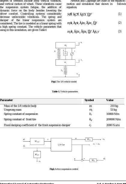
The 1/4 model 2 degree of freedom is illustrated in Error! Reference source not found.. The vehicle
degrees of freedom include body vertical vibration, and vertical motion of wheel. These vibrations cause the suspension system fatigue, the addition of dynamic force on the body besides lowering the driver comfort. Controlling systems considerably decrease unfavorable vibrations. The spring and damper of the linear suspension system are considered. The tire is modeled as a linear spring with a high spring constant. The vehicle parameters that using in this simulation, are given Table1
Newton and Lagrange are Base of the equation of motion and simulation that shown in following equation;
Fig1.The 1/4 vehicle model
Table 1. Vehicle parameters
Value Symbol
Parameter
210 kg
m
Mass of the 1/4 vehicle body
53 kg
f m
Unsprung mass
10000 N/m
f k
Spring constant of suspension
200000 N/m
tf k
Spring constant of front tire
2000 N.s/m
f c
Fixed damping coefficient of the front suspension damper
Fig2.Active suspension control
+ + =
&& &
MX CX KX F (1)
1 1&&+ &1+ 1− 2=
m x cx kx kx f (2)
2&&2+ 2− 1= + t
m x kx kx f k y (3)
2. Linear H-Infinity Controller Design
The design of linear suspension controllers that emphasize either passenger comfort or suspension deflection. The controllers in this section are designed using linear H∞ synthesis [13]. As is standard in the H∞ framework, the performance objectives are achieved via minimizing weighted transfer function norms. Weighting functions serve two purposes in the H∞ framework: They allow the direct comparison of different performance objectives with the same norm, and they allow for frequency information to be incorporated into the analysis. A block diagram of the H∞ control design interconnection for the active suspension problem is shown below. The quarter car model shown is used to design active suspension control laws.
The measured output or feedback signal y is the suspension deflectionx1−x3. The controller acts on
this signal to produce the control input, the hydraulic
actuator force fs. The block
W
n serves to model sensor noise in the measurement channel. Wnis set to a sensor noise value of 0.01 m.Wn=0.01In a more realistic design, Wn would be frequency
dependent and would serve to model the noise associated with the displacement sensor. The weight
ref
W
is used to scale the magnitude of the road disturbances. Assume that the maximum road disturbance is 7 cm and hence chooseWref;wref=0.07
The magnitude and frequency content of the control force fs are limited by the weighting function
act
w . Choose +
= +
100 50
13 500
act s w
s
The magnitude of the weight increases above 50 rad/s in order to limit the closed-loop bandwidth.Wac was gained using (4);
(100 / 13 *)
(
[
1 50 , 1 500] [
]
)
act
w = tf (4)
The purpose of the weighting functions (5) and is to keep the car deflection and the suspension
deflection small over the desired frequency ranges. In the first design, you are designing the controller for passenger comfort, and hence the car body deflection x1 is penalized.
(
)
=
1 8 * 2 * *5,[12 *5]
x
W tf pi pi
(5)
3. Designing of Controlling System in State Space through Closed-loop Method
Designing the controlling system through the closed - loop method shows the designing of controlling in state space. In this research, the efficiency coefficient of feedback has determined the second method of Liapunov (LQR). By considering LQR and having the Equation 6, the following steps will be:
x = Ax+Bu
&
(6)
Determine the matrix K of the optimal control vector
( )
= x( )
U t −k t (7)
So as to minimize the performance index Where Q is a definite (or semi positive-definite) Hermitian or real symmetric matrix and R is a positive-definite Hermitian real symmetric matrix. Note that the second term on the right-hand side of the equation (8) accounts for the expenditure of the energy of the control signals. The matrices Q and R determine the relative importance of the error and the expenditure of this energy. In this problem, it is assumed that the control vector U (t) unconstrained. As will be seen later, the linear control law given by Equation (7) is the optimal control law. Therefore, if the unknown element matrix K is determined so as to minimize the performance index, then U (t) = -k x (t) is optimal for any initial state x (0). The block diagram showing the optimal configuration is shown in Error! Reference source not found..
Fig3.Optimal control system
Solve optimization problem substituting Equation (7) into Equation (6)
(9)
(
)
x = Ax B
&
−
Kx
=
A B
−
K x
In following derivations, we assume that the matrix BK is stable, or that the eigenvalues of A-BK have negative real parts. Substituting Equation (7) into Equation (9) yields
(
)
0
= * * * .
J x Q x k Rkx dt
∞
+
∫
Following the discussion given in solving the parameter-optimizing problem, it is set as follows:
( ) ( * )
* * d x px
x Q K RK x dt
+ = −
Where P is positive-definite Hermitian or real symmetric matrix. Then it is concluded that
Comparing both sides of this last equation and noting that this equation must hold true for any x, so it requires (10)
(
)
(
)
(
)
* *A BK P P A BK
Q K RK
− + − =
− +
By the second method of Liapunov, if A-BK is stable matrix, there exists a positive definite matrix P that satisfies Equation (10). The P variables are all extracted from the Equation (10). By determining P, the index J will be obtained as follows:
(11)
(
)
( ) ( )
( ) ( )
0 = * * * . ** * 0 0
J x Q u k Rk x dt x Px
x Px x Px
∞
+ = − =
− ∞ ∞ +
∫
Since all eigenvalues of A-BK are assumed to have negative real parts, if →0. Therefore, it is:
(12)
( ) ( )
* 0 0
J x= Px
Since R has been assumed to be a positive – definite Hermitian or real symmetric matrix, it can be written as:
= *
R T T
Where T is a nonsingular matrix. Then Equation (10) can be written as
Which of which can be replaced as:
The minimization of J with respect to K requires the minimization of
With respect to K. Since this last expression is nonnegative, the minimum occurs when it is zero, or when
(13)
( )
11 * * 1 *
K T= − T − B P R B P= −
Equation (13) gives the optimal matrix K. Thus, the optimal control law to the quadratic optimal control problem when the performance index is given by equation (13) is linear and is given by
The P matrix in the Equation 14 should be satisfied with the following equation
(14)
1
* *
A P PA PBR B P Q+ − − +
Equation (14) is called the reduced-matrix Riccati equation. These steps have been taken to determine the optimal K matrix. The K obtained by LQR is used for feedback. In this paper Q and R are diagonal and unique matrix for simulations simplicity.
(
)
(
)
(
)
* * * *
* *
x Q K RK x x Px x Px
x A BK P P A BK x
+ = − − =
− − + −
& &
(
A BK
−
)
*
P P A BK
+
(
−
) (
+
Q K T T
+
* *
)
( )
1( )
11
* * * * * *
* 0
A P PA TK T B P TK T B P
PBR B P Q
− −
−
+ + − −
− + =
( )
1( )
1* * * * * *
x TK− T − B P TK− T − B P X
( )
.
( )
1*
( )
U t
= −
K x t
= −
R B Px t
−Fig5.Body vertical displacement
Fig6.Suspension Deflection
Fig7.Body vertical acceleration
Fig8.Frequency response of the vehicle acceleration
Simulation Result
Error! Reference source not found. shown the road input that all of the simulation output is based on that. Body displacement is shown in Error! Reference source not found.. Suspension deflection shown in Error! Reference source not found.. Vehicle vertical acceleration shown in Error! Reference source not found.. Vehicle ride has been optimized using H-infinity but the vertical acceleration have been increased so it is more than passive suspension and optimal control (LQR). Vehicle’s running speed is 90km/h in this simulation.
Error! Reference source not found. shown the vehicle ride using controllers and passive suspension. According to Error! Reference source not found., the vehicle ride comfort has been smooth using robust control so in 20 and 50 rad/sec the peak of resonance have been reduced. Although using robust control is worse than passive suspension on vehicle acceleration but the vehicle ride has been better. This figure shown using the LQR controllers is worth than H- infinity on the vehicle ride and acceleration control.
Conclusion
1/4 car model has been simulation. The vehicle vibration and ride comfort are tow determinant method that can be improved using controller systems. Robust control can help to improve ride comfort, but acceleration increasing caused by robust control. Optimal feedback control is better than H-Infinity to achieve vehicles behavior so using LQR the vehicle ride comfort and body acceleration can be reduced. As a result, using optimal control (LQR),
body vertical acceleration and ride comfort have been optimized.
References
[1]. Kumar A, Mahajan P, Mohan D, Varghese M. Tractor vibration severity and driver health: a study from rural India. J Agric Eng. Res; 80(4): (2001), 313–28,
[2]. Siphon Fang. Study of Control Method of Automotive Semi-active Suspension System Based on MR Damper. Ph.D. Dissertation, Chongqing University, Chongqing, China. 2006 (In Chinese).
[3]. R.G. Cobb, J.M. Sullivan, A. Das, L. Porter Davis, T. Tupper Hyde, T. Davis, Z.H. Rahman, J.T. Spanos, Vibration isolation and suspension system for precision payloads in space, Smart Materials & Structures 8 (6), (1999),798–812. [4]. Takubo N, Mizuno K. Accident analysis of
sports utility vehicles: human factors from statistical analysis and case studies. JSAE Review; 21:2000.
[5]. D.L. Platus, Negative-stiffness-mechanism vibration isolation systems, in: E.A. Derby, et al. (Eds.), Proceedings of SPIE Conference on Current Developments in Vibration Control for Optomechanical Systems, SPIE, vol. 3786, (1999),pp. 98–105.
[6]. M Soleymani, M Montazeri-Gh, R Amiryan. Adaptive fuzzy controller for vehicle active suspension system based on traffic conditions. Scientia Iranica B. 2012; 19(3): 443-453. [7]. R. Guclu, Fuzzy Logic Control of Seat
Vibrations of a Non-Linear Full Vehicle Model, Nonlinear Dynamics. 40, (2005), 21–34. [8]. H. Du, J. Lam, K.Y. Sze, Non-fragile output
feedback H1 vehicle suspension control using genetic algorithm, Engineering Applications of Artificial Intelligence 16 (2003) 667–680. [9]. Dukkipati RV, Pang J, Qatu MS, Sheng G,
Shuguang Road vehicle dynamics. Warrendae (PA): Society of Automotive Engineers; 2008. [10].Marek A, Ksiazek, Daniel Ziemianski, Optimal
driver seat suspension for a hybrid model of sitting human body, Journal of Terramechanics 49, (2012), 255–261.
[11].Alkhatib R., Jazar G. N. and Golnaraghi, M. F. 2004. Optimal design of passive linear suspension using genetic Algorithm. Journal of Sound and Vibration. 275, 665–691.
[12].Hassanin H. S., Rabeih A. M., El-Demerdash S. M., and Younes K. Y. 2008. Active Suspension of Highway Truck Seat Using Genetic Algorithms.SAE International. 2008-01- 1458. [13]. Fialho, I, and Balas, G.J, "Design of nonlinear
controllers for active vehicle suspensions using
parameter-varying control synthesis," Vehicle Systems Dynamics, 33(2000). Pp.351-370..