DOI:10.5545/sv-jme.2017.4915 Original Scientific Paper Accepted for publication: 2018-01-25
Introduction ofWelds into the Dynamic
Model of Laminated Structures
Ogrinec, P. – Čepon, G. – Boltežar, M.
Review Paper —DOI: 10.5545/sv-jme.2017.4027 Accepted for publication: 2017-02-12
Introduction of Welds into the Dynamic Model of Laminated
Structures
Primož Ogrinec — Gregor ˇCepon*— Miha Boltežar
University of Ljubljana, Faculty of Mechanical Engineering, Slovenia
Laminated structures, like an electric stator package, exhibit orthotropic behaviour and high levels of internal damping due to the inter-laminar friction forces. Modelling the complex geometry, number of laminae, spatial pressure distribution, and the effects of welds on the dynamic response of laminated structure remains a challenging issue. The presence of welds, that serve as a physical connection between laminae, results in non-uniform pressure distribution between laminae. Usually orthotropic material properties are proposed to account for lower stiffness in the sheet stacking direction. These models assume uniform distribution of friction forces and may even lead to occurrence of additional, unrealistic mode shapes. In this paper the dynamics model of the electric machine stator is proposed that employs a new contact formulation using beam elements, characterized by stiffness and damping parameters in the tangential direction and nonlinear contact stiffness in the normal contact direction. The welds and the welding process itself are represented using spring-thermo elasto-plastic bar model. As the contact model assumes nonuniform pressure distribution it is possible to include the effect of residual stresses that occur after the welding process. The validity of developed numerical model is demonstrated by comparing numerically and experimentally obtained eigenfrequencies and modes for three different stator packets that differ in geometry, position and the number of welds.
Keywords: Laminated structure, electric stator package, dynamics, contact model, weld, modal analysis
Highlights
• Laminated structures are significantly more flexible as their solid counterparts and are often welded to preserve shape. • Welding process affects the pressure distribution between the laminae, which greatly affects its dynamic behaviour.
• A two stage model is presented for modelling steel laminated structures, which determines the contact parameters based on the pressure distribution between the laminae.
• Experimental modal analysis was used to validate the model.
0 INTRODUCTION
In order to reduce Eddy currents and consequently heat losses, the magnetic cores in electrical devices are usually made of large number of thin metal sheets. These sheets are stacked together and are often line welded in order to preserve shape. The magnetostriction and magetic forces are a phenomena accompanying the magnetisation process and present
a problem in terms of vibrations. The intensity
of vibrations depends on the dynamic properties of the structure and the magnitude of the excitation phenomena. By optimizing the design of the laminated structure, the resonant frequencies can be avoided.
In order to predict the dynamic response of such structures a valid structural model must be developed, including an effective and reliable model of a contact-dependent structure, with friction
between the laminae. Laminated structures are
usually substantially more flexible than the equivalent
homogeneous structures [1] and [2], and exhibit
orthotropic behavior and high levels of internal
damping due to the interlaminar friction forces[3]and
[4]. The numerical model of a laminated structure
has to account for the pressure distribution between laminae, as it influences the stiffness distribution
within the structure [4] to [6]. The authors of [6]
observed a significant increase of the eigenfrequencies even for small increases of the pressure between
the laminae. Some analytical models also exist
for the estimation of modal parameters of a stator
packet [7] and [8]; however, they fail to take
the frictional contact between the laminae into
account. An efficient contact model in the field
of multibody dynamics was presented in [9], which
separates between the normal and tangential influences of contact parameters on a highly flexible body. Laminated structures are also commonly modelled
using orthotropic material properties [10], [11] and
[12]that are obtained experimentally, by measuring a
real structure and consequently updating the numerical
model. Simplified models are used in order to
reduce the complexity, number of components in the analysis, number of details and number of degrees of freedom. Many of these models were developed for the modelling of composite structures. These methods are commonly referred to as homogenisation
methods [12]. Some of the methods employ
simplifying the laminated structure by determining
equivalent homogeneous material properties[13]and
[14]. A more sophisticated analytical solution
was proposed in [15] for determining the laminated
structure’s equivalent elasticity matrix. The paper[16]
describes the Reissner- Mindlin model for numerical
homogenisation of orthotropic structures. A very
thorough review of these homogenisation methods is
presented in[17].
Modelling of the structure using the orthotropic material properties is performed by modifying the shear and elastic moduli of the equivalent
homogeneous structure. The obtained material
parameters are applicable to the specific laminated structure and assume a uniform pressure distribution
and friction forces between the lamina. Thus,
each modification regarding the geometry, number of laminae, number and position of welds, etc. has to be evaluated experimentally and then the valid numerical model can be created. Moreover, the introduction of orthotropic material properties can also lead to the
occurrence of additional unrealistic mode shapes[4].
The usage of orthotropic material properties in the case of cylindrically symmetric structures also means that the modes occur in pairs, at similar frequencies. This is, however, not necessarily the case when dealing with welded laminated structures, as shown in this paper using the extended linear contact model.
Just recently, the authors of [4] developed a
new general numerical model of laminated structures that accounts for the non-uniform distribution of inter-laminar friction forces. This numerical model employs contact elements characterized by stiffness and damping parameters in a tangential contact direction and non-linear contact stiffness in the
normal contact direction. The algorithm for
modelling of a contact using beam elements made it possible to accurately predict the eigenfrequencies and mode shapes for various configurations of clamped laminated stacks. In this paper the model presented in
[4]is extended in order to predict the modal parameters
of welded electrical stator packages.
The originally proposed algorithm for modelling
a contact-dependent structure in [4] was used to
model simple cubic laminated stacks without welds. Here, the developed model is general and may be applicable to geometrically complex laminated structures, e.g., electrical stators. As the contact model
was thoroughly tested in[4], where the influence of
stack height, surface treatment of the laminae and steel types were analysed on 18 different configurations of the packages. Therefore, only the influence of
non-uniform contact pressure distribution is of interest in the experimental analysis in this paper.
Effect of welds is additionally introduced into the laminated structure model as the stators are commonly line welded to preserve stack geometry. The welds serve as a physical connection between laminae and due to residual stresses influence the inter laminar pressure distribution within stator packet. Residual stresses result in a force, that influence the frictional conditions between the laminae. Analytical methods to deduce the residual stresses usually follow the
calculation of heat flow and thermal expansion [18],
where material properties are temperature dependent
[19]. Some authors model the heat flow and thermal
expansion through the continuous material using 3D
[20]or simplified with 1D finite elements[21].
Here the weld and the welding process itself was modeled by spring-thermo-elasto-plastic bar model
[22]. To introduce the weld model into the laminated
structures the formulation presented in [22] had
to be additionally extended in order to enable the implementation of the model in a finite element environment. To validate the developed model of laminated structures several stator packets that differ in geometry, number of laminae and position of welds were experimentally analysed.
The article is organised as follows. The second section presents the development of the numerical model, its application to the complex geometry of a stator packet and the modelling of the welds. In third section, the experimental procedure is presented. The fourth section presents results and the validation of the model based on the three different stator packets.
1 NUMERICAL MODEL
Laminated structures are usually modelled using the orthotropic material properties, which implies that the shear and tension-compression modulus are independent. Here the contact description between two adjacent laminae is based on two stage linear contact
model as it is presented in [4]. In the first stage
the link elements are spanned between laminae and pressure distribution is deduced. In the second stage the link elements are replaced with beam elements (Fig. 1). A linear relation is assumed between the computed pressure distribution and the beam shear
modulusGf in order to model the effect of the friction
forces and the sliding. In the first stage the lamina surface pressure distribution is computed using static analysis based on known clamping pressure. In this paper the first stage of the contact formulation is extended to account for the influence of the welding
a)
b)
Fig. 1.Linear contact model[4]; a) first stage, b) second stage
process on the pressure distribution between laminae. The application of the proposed dynamic model of a contact using beam/link finite elements to the stator
packet is presented in Fig. 2. Finite elements on
the laminae are of different sizes and shapes. As the contact parameters are proportional to the size of a finite element, the geometry of each individual element had to be identified. This was not required in
[4] as the authors applied the model only on simple
geometry, which was meshed with an equally sized rectangular finite elements. The deformation pattern of applied beam finite elements used for modelling the contact conditions between the laminae consist of flexural, shear and axial deformations. Only the shear and compressional deformations are taken into account in the contact model. The shear deformation, that describes the frictional contact between laminae, is assumed to be linear. Linearisation enables the application of implicit methods in the framework of linear dynamics.
Beam finite elements were proposed to model the contact elements and shell elements to model the laminae. The beam elements had the cross-section area equivalent to the area of the corresponding shell elements on the adjacent laminae. The length of the beam elements was equal to the height of
an individual lamina. It was observed that the
material properties of the laminae influence mainly the in-plane modes of the structure, however the frictional contact parameters have the biggest influence on the out-of-plane modes. Compressional deformation is also allowed, and is used to determine pressure distribution between laminae in the first stage of the linear contact model.
1.1 Introduction of Welds into Laminated Structure Model In this section the effect of welds on the dynamical behaviour of stator packet is identified and integrated in the linear contact model.
Before the welding process the stator packets were compressed with 2bar of pressure. The packets were line welded in several places along the circumference, Fig. 3. The number of welds varied depending on the type of the stator packet. Assuming near and far regions of the weld, the welding process can be modelled with a spring-thermo-elasto-plastic bar
model[22]. A mathematical model for prediction of
the residual stresses is presented in Fig. 4. The weld model is based on thermo-elasto-plastic bar, where
A represents the cross section area of the weld, E
the Youngs modulus andα as its coefficient of linear
thermal expansion, (Fig. 4). The Keq stands for the
equivalent stiffness of the spring, that represents the part of the structure that is not affected by the heat treatment (welding process). Near regions of the weld are modelled using a thermo elasto plastic bar, which is subjected to deformations due to the clamping force and thermal expansion, during the welding process. Ideal elasto plastic material is proposed. As the far region is not in the heat affected region it can be represented as a spring, that deforms elastically during the clamping process.
The welding process is modelled in four stages: In the first stage, the packet is compressed with the axial
forceF. The compression results in a deformationu.
The weld that is represented with thermo-elasto-plastic
bar is then exposed to a temperature gradient ∆T,
which heats the bar to its melting point. During the heating process the bar expands, thus the clamping force in the weld region reduces. It is assumed that the elastic modulus and the yield strength of the stack
material reduces linearly with temperature[22]:
σy(T) =σ0
1−TT
m
, (1)
E(T) =E0
1−TT
m
, (2)
where E0 and σ0 represent the values of elastic
modulus and yield stress at room temperature, T
represents the temperature, which ranges from room to
melting temperature, andTm the melting temperature
of the laminae material. The melting temperature of
1450oC was proposed for all three stator packets. At
melting temperature the stresses in the weld are equal to zero. In the third stage of the welding process the weld cools from the solidification to the surrounding
Fig. 2.Shell elements (laminae) connected via frictional contact elements (beam)
Fig. 3.Line welds on the stator packet.
a)
Thermo-elasto-plastic bar Equivalent spring of the material
in the far field
Keq
A, E,α
b)
Fig. 4.Modelling of the welded laminated structure; a)schematic representation of near and far field of the weld model, b)model of the
weld for prediction of residual stresses
temperature. The governing equation in the cooling phase can be written as:
σ= (keq
h +E)ε. (3)
The keq represents the equivalent stiffness of the
far region of the packet, h the height of the packet,
E the Young modulus of the stator material and ε
the deformation in the stator stacking direction. The
equivalent stiffness of the far region of the packetkeq
can be obtained using the following equation:
keq=A E
h . (4)
After the cooling process, the clamping force is removed, thus the spring modelling the far region expands and the axial load on the bar is applied. Stresses in the weld can be higher than the yield stress of the material. When the stresses reach the yield stress, the governing equation changes to
σ=keq
h ε+σ0. (5)
Considering the yield stress, it is possible to iteratively calculate the deformation of the weld itself. Resulting deformations can be applied to the nodes of the laminated structure, that represent the end points of the weld. Based on this deformations it is possible to deduce the pressure distribution in the stator packet due to the welding process (Fig. 5). The four stages of
Fig. 5.Pressure distribution between the laminae after the welding process
the welding are schematically presented in Fig. 6.
2 VALIDATION OF THE DEVELOPED NUMERICAL MODEL
¢T -¢T
F F F
F F F
u ≠ 0
σ > 0 uσ = 0 ≠ 0 uσ < 0 ≠ 0 uσ << 0 ≈ 0
Stage I. Stage II. Stage III. Stage IV.
Fig. 6.Modelling of the residual strains and stresses during welding
are presented in the Table 1 and shown in Fig. 7. Experimentally obtained modal parameters were used to deduce the material parameters, as well as to validate the numerical model.
As the stator packets 1 and 2 had the same lamina geometry, it was possible to deduce the lamina material and contact parameters based on experimentally identified modal parameters of stator package 1. The identified parameters were then used to predict the eigen frequencies and mode shapes for the stator package 2. This enabled the validation of the developed numerical model of laminated structures
with welds. The stator package 3 was included
into the analysis to demonstrate the influence of asymmetrically distributed welds along the stator perimeter.
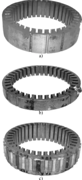
Table 1.Stator packets under investigation
Packet nr. Diameter[mm] Laminaenr. thickness [mm]Lamina Nr. of welds
1 140 70 0.5 8 (symmetric)
2 140 37 0.5 8 (symmetric)
3 108 55 0.5 7 (asymmetric)
2.1 Experimental Modal Analysis
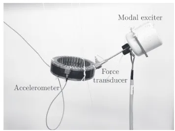
In order to obtain the Accelerance (frequency response function), the system was excited with an electrodynamic shaker, with frequency range up to 6.4 kHz (Fig. 9). The excitation performed with the electrodynamic shaker was necessary due to the high levels of structural damping of the stator packets. The response of the system was measured with a rowing three axial accelerometer. The accelerometer was positioned on two bands around the circumference of each stator packet. The positions of the accelerometer can be seen in Fig. 8.
The stator packets exhibit distinct in-plane and out-of-plane modes. All modes occur in pairs and are shifted along the symmetry axis. The selected
a)
b)
c)
Fig. 7.Stator packets under investigation; a) packet 1, b) packet 2, c) packet 3
mode shapes are presented in Fig. 10. The measured eigenfrequencies are presented in the Tables 3 to 5 and are compared with the results of the numerical model.
Fig. 8.Accelerometer positions during EMA
Fig. 9.Experimental setup
number and distribution of welds. Therefore it is possible to validate numerical model in the fist stage by comparing the eigenfrequencies corresponding to in-plane modes.
The value of elastic modulus was 206 GPa for all three laminae, and the density value of 7850
kg/m3 was used. In Fig. 11 the comparison between
experimentally and numerically obtained mode shape
for first in-plane mode is presented. Based on
error assessment it is evident that numerical model accurately predicts the value of the eigenfrequencies associated with in-plane modes.
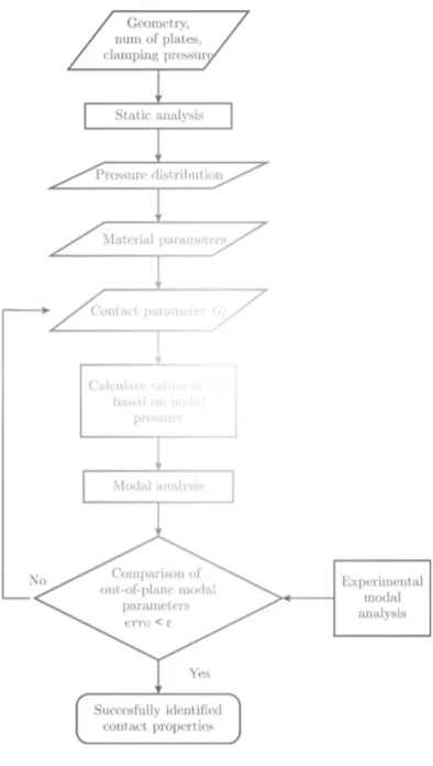
2.3 Identification of Contact Parameters
The simulation procedure to deduce the contact parameters for given lamina and consequently modal parameters is presented in Fig. 12.
It is assumed in this paper that contact parameter
Gf is independent of the pressure distribution within
stator package and is not influenced by the number
and position of welds. The contact parameter Gf
is presumably a function of the frictional conditions between the two laminae. The contact parameter for stator packets 1 and 2 that were made from the same laminae, were obtained based on measurement of stator packet 1.
The identification of contact parameters relies on experimentally identified modal parameters that
a) b)
c) d)
Fig. 10.Mode shapes; a) 1stin-plane mode, b) 3rdin-plane mode, c) 1st out-of-plane mode, d) 2ndout-of-plane mode
a) b)
Fig. 11.Third mode shape (1stin-plane mode) for stator packet 1; a) numerical model, a) EMA
correspond to out-of-plane modes. The optimization function is defined as:
errG=
∑
i
fexp,i−fnum,i(Gf)2, (6)
where fexp,i is the i-th experimentally identified
eigenfrequency and fnum,iis the numerically identified
eigenfrequency. In the process of calculating the
contact parameter Gf only the eigenfrequencies
corresponding to out-of-plane modes were used,
Eq. (6). The algorithm to obtain contact parameterGf
is schematically presented in Fig. 12.
Based on the geometry of the stator packet the finite element model is generated. The packet is meshed and populated with link/beam elements. The cross section of each beam is calculated, based on the finite element mesh of the laminae. In the first contact stage all of the link elements have the same elastic modulus. By knowing clamping force and the number as well as the position of welds the pressure distribution between the laminae is calculated (Fig. 5). In the next step
the initial value for the material shear modulusGf is selected. As the calculated nodal pressure between the laminae is non-uniformly distributed it is necessary to deduce the element shear modulus for each individual beam element:
Gf,i(p) =Gf ppi,beam
max , (7)
where pi,beam is the nodal pressure at given node
i and pmax is the max. value of identified nodal
pressure within the lamina. The shear modulusGf,i(p)
represents the friction forces by modeling beam shear deformation between two nodes on adjacent lamina. Based on the identified contact parameter the out-of plane modes are numerically predicted and the cost
function errGis estimated according to Eq. (6). If the
cost function is not satisfied the optimization process
is repeated with new value of contact parameterGf.
Using this procedure it is possible to deduce the contact parameter for the given type of lamina. Based on the
Fig. 12.Simulation algorithm
optimization algorithm presented in Fig. 12 the contact
parameterGf was identified for the stator package 1
Table 2.Identified contact parameterGf
Stator packet Contact parameterGf[GPa] 1, 2 0.3962
3 0.1744
and 3. The values are listed in Table 2. In this way it was possible to validate the developed numerical model of laminated structures with welds.
a) b)
Fig. 13.First mode shape (out of plane) for stator packet 1; a) numerical model, a) EMA
Table 3. Comparison of numerically and experimentally obtained eigenfrequencies for packet 1
Experiment Numerical model Mode Mode plane Eigenfreq. [Hz] Eigenfreq. [Hz] Diff. [%]
1 out-of-plane 318.40 307.43 -3.45 2 out-of-plane 346.80 309.70 -11.98 3 in-plane 432.54 427.17 -1.24 4 in-plane 444.71 429.73 -3.37 5 out-of-plane 702.37 703.11 0.11 6 out-of-plane 892.97 837.03 -6.26
The experimentally obtained values were used as a reference to estimate the relative error of numerical
model. It can be observed, that the difference
between eigenfrequencies for the out-of-plane modes is not negligible. However the agreement can be considered satisfactory as the laminated structures are also subjected to great deal of uncertainties during the manufacturing process. The generality of proposed numerical model is demonstrated by accurately predicting the eigenfrequencies for the
stator package 2. As the stator package 1 and
2 were made from the same type of lamina the
contact parameterG(1)
f was obtained based on updating
algorithm using stator package 1. Although the
stator package 2 had different number of laminae and with this a different pressure distribution within stator package the numerical model correctly predicted the values of eigenfrequencies and corresponding modal
shapes. Thus, once the contact parameter Gf is
identified for given lamina it is possible to predict model parameters of stator packages that differ in geometry, clamping pressure and the number and position of welds.
[1] Garvey, S.D. (1989) The vibrational behaviour of laminated components in electrical machines. 4th International Conference on Electrical Machines and Drives, p. 226-231.
[2] Wang, H., Williams, K. (1997). Effects of laminations on the vibrational behaviour of electrical machine stators.
Journal of Sound and Vibration, vol. 202, no. 5, p. 703-715,
DOI:10.1006/jsvi.1996.0845.
[3] Popp, K., Panning, L., Sextro, W. (2003). Vibration damping by friction forces: theory and applications. Modal Analysis, vol. 9, no. 3-4, p. 419–448, DOI:10.1177/107754603030780. [4] Pirnat, M., Čepon, G., Boltežar, M. (2013). Introduction of
the linear contact model in the dynamic model of laminated structure dynamics: An experimental and numerical
identification. Mechanism and Machine Theory, vol. 64, p. 144–154, DOI:10.1016/j.mechmachtheory.2013.02.003. [5] Javorski, M., Čepon, G., Slavič, J., Boltežar, M. (2013).
A generalized magnetostrictive-forces approach to the computation of the magnetostriction-induced vibration of laminated steel structures. IEEE Transactions on Magnetics, vol. 49, no. 11, p. 5446–5453, DOI:10.1109/ TMAG.2013.2269316.
[6] Kim, Y.C., Kim, K.W. (2006). Influence of lamination pressure upon the stiffness of laminated rotor. JSME International Journal Series C Mechanical Systems, Machine Elements
Table 4. Comparison of numerically and experimentally obtained eigenfrequencies for packet 2
Experiment Numerical model Mode Mode plane Eigenfreq. [Hz] Eigenfreq. [Hz] Diff. [%]
1 out-of-plane 195.37 219.98 12.55
2 out-of-plane 262.35 212.13 -15.71
3 in-plane 425.22 423.14 -0.49
4 in-plane 447.39 425.53 -4.89
5 out-of-plane 637.35 656.88 3.06
6 out-of-plane 1045.29 969.13 -7.29
Table 5. Comparison of numerically and experimentally obtained eigenfrequencies for packet 3
Experiment Numerical model Mode Mode plane Eigenfreq. [Hz] Eigenfreq. [Hz] Diff. [%]
1 out-of-plane 342.95 342.83 -0.04
2 out-of-plane 456.75 443.85 -2.82
3 in-plane 572.57 590.49 3.13
4 in-plane 613.26 656.87 7.11
5 out-of-plane 690.16 678.13 -1.74
6 out-of-plane 820.00 764.73 -6.74
Moreover the proper modeling of the weld and the welding process itself can be demonstrated by observing eigenfrequencies of stator package 3. As the stator packets 1 and 2 have symmetrically distributed welds around the perimeter the first and the second mode shapes appear in pairs and shifted along the symmetry axis. It can be observed that first two eigenfrequencies are located closely together (Table 3). However this is not the case for the stator package 3 (Table 5), as the experimentally obtained first and second eigenfrequencies are placed distinctly apart. This is the result of unsymmetrically distributed welds along the perimeter of the stack, and the developed numerical model successfully predicted this behaviour.
3 CONCLUSION
In this paper a numerical model of laminated structures is presented in order to predict the eigenfrequencies and modal shapes of laminated stator packages. The model uses shell and link/beam finite elements to model the contact conditions between the laminae that expedite the computation time of the modal analysis, thus practically justifying the modelling of each individual plate in the stator package. The welds and the welding process are represented
using spring-thermo elasto-plastic bar model. In
order to identify contact parameters and to validate the numerical model three different stator packages
were analyzed. The experimentally identified
eigenfrequencies and corresponding mode shapes were
used in the optimization process to extract the values of contact parameters.
It has been shown that the in-plane modes are in direct correlation with material properties of the lamina. The out-of-plane modes are however governed by the value of contact parameters. The generality of proposed numerical model is demonstrated with the stator package 2 where the contact parameters were identified based on stator package 1. Although the stator package 2 had different number of laminae comparing to to stator package 1 the numerical model correctly predicted the values of eigenfrequencies and corresponding modal shapes.
Moreover the proper modeling of the weld and the welding process itself is demonstrated on the stator package 3. In this case the experimentally obtained first and second eigenfrequencies are located distinctly apart which is the result of unsymmetrically distributed welds along the perimeter of the stack. In order to successfully predict this behaviour it is necessary to model the physical connection at the weld location as well as the influence of the welding process on the pressure distribution within the stator package.
4 ACKNOWLEDGEMENTS
The authors acknowledge the partial financial support from the research project EVA4Green.
5 REFERENCES
[1] S.D. Garvey. The vibrational behaviour of
laminated components in electrical machines. In
Fourth International Conference on Electrical Machines and Drives, 1989.
[2] H. Wang and K. Williams. Effects of laminations on the vibrational behaviour of electrical machine
stators. Journal of Sound and Vibration,
202(5):703–715, 1997.
[3] K. Popp, L. Panning, and W. Sextro. Vibration
damping by friction forces: theory and
applications. Modal Analysis, 9(3-4):419–448,
2003.
[4] M. Pirnat, G. ˇCepon, and M. Boltežar. Introduction of the linear contact model in the dynamic model of laminated structure
dynamics: an experimental and numerical
identification. Mechanism and Machine Theory,
64:144–154, 2013. 8
Table 4. Comparison of numerically and experimentally obtained eigenfrequencies for packet 2
Experiment Numerical model Mode Mode plane Eigenfreq. [Hz] Eigenfreq. [Hz] Diff. [%]
1 out-of-plane 195.37 219.98 12.55
2 out-of-plane 262.35 212.13 -15.71
3 in-plane 425.22 423.14 -0.49
4 in-plane 447.39 425.53 -4.89
5 out-of-plane 637.35 656.88 3.06
6 out-of-plane 1045.29 969.13 -7.29
Table 5. Comparison of numerically and experimentally obtained eigenfrequencies for packet 3
Experiment Numerical model Mode Mode plane Eigenfreq. [Hz] Eigenfreq. [Hz] Diff. [%]
1 out-of-plane 342.95 342.83 -0.04
2 out-of-plane 456.75 443.85 -2.82
3 in-plane 572.57 590.49 3.13
4 in-plane 613.26 656.87 7.11
5 out-of-plane 690.16 678.13 -1.74
6 out-of-plane 820.00 764.73 -6.74
Moreover the proper modeling of the weld and the welding process itself can be demonstrated by observing eigenfrequencies of stator package 3. As the stator packets 1 and 2 have symmetrically distributed welds around the perimeter the first and the second mode shapes appear in pairs and shifted along the symmetry axis. It can be observed that first two eigenfrequencies are located closely together (Table 3). However this is not the case for the stator package 3 (Table 5), as the experimentally obtained first and second eigenfrequencies are placed distinctly apart. This is the result of unsymmetrically distributed welds along the perimeter of the stack, and the developed numerical model successfully predicted this behaviour.
3 CONCLUSION
In this paper a numerical model of laminated structures is presented in order to predict the eigenfrequencies and modal shapes of laminated stator packages. The model uses shell and link/beam finite elements to model the contact conditions between the laminae that expedite the computation time of the modal analysis, thus practically justifying the modelling of each individual plate in the stator package. The welds and the welding process are represented
using spring-thermo elasto-plastic bar model. In
order to identify contact parameters and to validate the numerical model three different stator packages
were analyzed. The experimentally identified
eigenfrequencies and corresponding mode shapes were
used in the optimization process to extract the values of contact parameters.
It has been shown that the in-plane modes are in direct correlation with material properties of the lamina. The out-of-plane modes are however governed by the value of contact parameters. The generality of proposed numerical model is demonstrated with the stator package 2 where the contact parameters were identified based on stator package 1. Although the stator package 2 had different number of laminae comparing to to stator package 1 the numerical model correctly predicted the values of eigenfrequencies and corresponding modal shapes.
Moreover the proper modeling of the weld and the welding process itself is demonstrated on the stator package 3. In this case the experimentally obtained first and second eigenfrequencies are located distinctly apart which is the result of unsymmetrically distributed welds along the perimeter of the stack. In order to successfully predict this behaviour it is necessary to model the physical connection at the weld location as well as the influence of the welding process on the pressure distribution within the stator package.
4 ACKNOWLEDGEMENTS
The authors acknowledge the partial financial support from the research project EVA4Green.
5 REFERENCES
[1] S.D. Garvey. The vibrational behaviour of
laminated components in electrical machines. In
Fourth International Conference on Electrical Machines and Drives, 1989.
[2] H. Wang and K. Williams. Effects of laminations on the vibrational behaviour of electrical machine
stators. Journal of Sound and Vibration,
202(5):703–715, 1997.
[3] K. Popp, L. Panning, and W. Sextro. Vibration
damping by friction forces: theory and
applications. Modal Analysis, 9(3-4):419–448,
2003.
[4] M. Pirnat, G. ˇCepon, and M. Boltežar. Introduction of the linear contact model in the dynamic model of laminated structure
dynamics: an experimental and numerical
identification. Mechanism and Machine Theory,
64:144–154, 2013.
Composite Materials. PhD thesis, INRIA, Le Chesnay Cedex.
[16] Cecchi, A., Sab, K. (2007). A homogenized reissner–mindlin model for orthotropic periodic plates: Application to brickwork panels. International Journal of Solids and Structures, vol. 44, no. 18-19, p. 6055-6079, DOI:10.1016/j.ijsolstr.2007.02.009. [17] Kalamkarov, A.L., Andrianov, I.V., Danishevs’kyy, V.V. (2009).
Asymptotic homogenization of composite materials and
structures. Applied Mechanics Reviews, vol. 62, no. 3, p. 030802, DOI:10.1115/1.3090830.
[18] Rogante, M., Cesari, F.G., Ferrari, G. (2009). Analytical method for residual stresses determination in thin welded joints.
Multidiscipline Modeling in Materials and Structures, vol. 5, no. 3, p. 269-276, DOI:10.1163/157361109789016998. [19] Teng, T.L., Lin, C.C. (1998). Effect of welding conditions on
residual stresses due to butt welds. International Journal of Pressure Vessels and Piping, vol. 75, no. 12, p. 857-864,
DOI:10.1016/S0308-0161(98)00084-2.
[20] Deng, D., Murakawa, H. (2006). Numerical simulation of temperature field and residual stress in multi-pass welds in stainless steel pipe and comparison with experimental measurements. Computational Materials Science, vol. 37, no. 3, p. 269-277, DOI:10.1016/j.commatsci.2005.07.007. [21] Salvini, P., Vivio, F., Vullo, V. (2000). A spot weld finite element
for structural modelling. International Journal of Fatigue, vol.
22, no. 8, p, 645-656, DOI:10.1016/S0142-1123(00)00044-X. [22] Mandal, N.R., Sundar, C.V.N. (1997). Analysis of welding
shrinkage. Welding Journal, Welding Research Supplement,
vol. 76, no. 6, p. 233-238. Experimental study. Journal of Sound and Vibration, vol. 115,
no. 1, p. 13-23, DOI:10.1016/0022-460X(87)90489-5. [8] Verma, S.P., Singal, R.K., Williams, K. (1987). Vibration
behaviour of stators of electrical machines, part I: Theoretical
study. Journal of Sound and Vibration, vol. 115, no. 1, p. 1–12,
DOI:10.1016/0022-460X(87)90488-3.
[9] Calì, M., Oliveri, S.M., Sequenzia, G., Fatuzzo, G. (2017). An effective model for the sliding contact forces in a multibody environment. Advances on Mechanics, Design Engineering and Manufacturing, p. 675-685. Springer, Cham,
DOI:10.1007/978-3-319-45781-9_68.
[10] Wang, C., Lai, J.C.S., Astfalck, A. (2004). Sound power radiated from an inverter driven induction motor II: Numerical analysis.
IEE Proceedings - Electric Power Applications, vol. 151, o. 3, p. 341-348, DOI:10.1049/ip-epa:20040120.
[11] Van der Giet, M., Kasper, K., De Doncker, R.W., Hameyer, K. (2012). Material parameters for the structural dynamic simulation of electrical machines. XXth International
Conference on Electrical Machines, p. 2994-3000,
DOI:10.1109/ICElMach.2012.6350314.
[12] Millithaler, P., Sadoulet-Reboul, É., Ouisse, M., É. Dupont, J.-B., Bouhaddi, N. (2015). Structural dynamics of electric machine stators: Modelling guidelines and identification of three-dimensional equivalent material properties for multi-layered orthotropic laminates. Journal of Sound and Vibration,
vol. 348, p. 185-205, DOI:10.1016/j.jsv.2015.03.010. [13] Berthelot, J.M. (2012). Composite Materials: Mechanical
Behavior and Structural Analysis. Springer -Verlag, New York,
![Fig. 1. Linear contact model [4]; a) first stage, b) second stage](https://thumb-us.123doks.com/thumbv2/123dok_us/8948656.1858024/3.598.108.266.86.259/fig-linear-contact-model-rst-stage-second-stage.webp)