0 INTRODUCTION
Robot spot welding is nowadays present in several industries all around the globe. These systems
increase production efficiency [1] and increase the
quality of the products. The physical burden on the human workforce is relieved as well as the stress on
their health [2]. Many of these systems are present in
automotive industry [3] where contact spot welding
is mainly used [4]. Besides automotive industry the
robotic spot welding is present also in other industries
[5] and [6].
Industrial robots have high position repeatability, but have at least a grade worse absolute position accuracy [7] to [9]. The robots are mainly programmed on-line where all robot points are defined or recalculated in regard to the base coordinate system of the robot. However, improvements in technology enable off-line robot programming to be used more and more nowadays. This type of programming saves the robot points in regard to the virtual robot coordinate systems. When these points are transferred to the real system on the shop-floor, usually a point
position difference is present and the literature [10]
specifies this error as positional absolute error or kinematic position error. The same problem occurs
when machine or robot vision [11] systems are used
[12], where points in camera coordinate system need to
be transformed into the robot base coordinate system. When transforming coordinates from vision system to the robot system, usually the ideal robot kinematic model is used, but real kinematic parameters differ. For this reason an absolute calibration procedure is a must to accurately position the robot on proper position defined by the vision system.
To reduce or eliminate the absolute error, manual calibration of the robot system is usually used. But this conventional approach requires a large amount of calibration points, which results in a long calibration time and is therefore not suitable for shop-floor production. In the field of robotic automatic absolute error calibration procedures the reader can find several approaches using 1D and 2D vision calibration systems [13] to [16], calibration with laser trackers
[17], image comparison [18], visual touch-up [19] and hybrid sensors using Kalman filters [20].
Most of the presented work for kinematic calibration of the robot system in the previous paragraph was tested in laboratory and used expensive dedicated measurement equipment or additional equipment needed to be installed that limits robot working space. These academic approaches have a large influence on calibration methods development, but are usually not implemented in shop-floor
Robust Visual Touch-Up Calibration Method
in Robot Laser Spot Welding Application
Rejc, J. – Munih, M.
Jure Rejc* – Marko Munih
University of Ljubljana, Faculty of Electrical Engineering, Slovenia
The article is describing the use of visual touch-up calibration method for defining the mathematical transformations used in a shop-floor measurement and welding robot cell in the protector assembly process. The presented system is designed as a robust and cheap solution, using only the equipment needed for the production tasks in the robot cell. The main goal of the presented system is to use vision measurement system for measuring and calibration procedures and laser welding equipment to weld two protector assembly parts together where positioning tolerances are very narrow. These narrow tolerances forced us to implement auto-checking and auto-calibration procedures for all necessary mathematical aspects in the robot cell, based on the robust visual touch-up method. To demonstrate adequate solution in the measurement, calibration and also the production sequences, the graphs show production statistical results over a one year production period.
Keywords: robot welding, visual touch-up, calibration, kinematic error, transformations
Highlights
production facilities [21]. All presented drawbacks forced us to develop the robot automated visual inspection (AVI) and measurement system for measuring and laser welding cell in a way that used previously installed equipment for measuring, welding and for all necessary calibration procedures. Among the presented approaches from the literature the simplified visual touch-up approach was implemented. The article presents the robot cell design, the automatic position error eliminating procedures and the results of installed approach. Presented is statistics for the whole year production analysis.
1 THE ROBOT CELL
1.1 The Protector
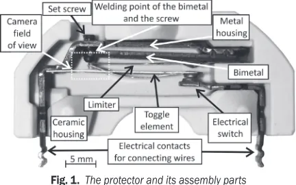
The robot cell workpiece called protector (Fig. 1) is
a control and safety element incorporated into classic cast-iron cooking plates manufactured in different diameters and nominal power. The task of the protector is to turn off the power supply of the heating winding hobs in the event of overheating when the temperature reaches 400 °C ± 50 °C.
The basic components of the protector (Figs. 1
and 2) are: ceramic housing, 1.2 mm thick bimetal
with the set screw, limiter, toggle element, electrical switch and electrical contacts for connecting wires. When the temperature of the cooking plate is rising, the bimetal bends in the protector and exerts force via the set screw on the limiter. When the pressure on the limiter is high enough, it triggers the toggle element, which represents half of the electrical switch.
Fig. 1. The protector and its assembly parts
The protector manufacturer was forced to change its design in 2013 for two reasons. The set screw was previously fixed to the bimetal with special glue paint. This solution was practical, but it sometimes happened that the set screw was not fixed enough and the protector switch-off temperature moved outside
the tolerances. Also, this special paint was expensive, which called for a cheaper and more reliable solution. The protector redesign declared that the set screw is bonded with the bimetal by laser welding these two assembly parts together.
Fig. 2. The field of view of the visual inspection system
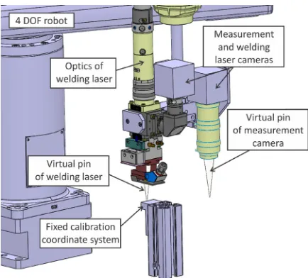
1.2 The Robot Workspace and Attached Equipment
The robot cell (Fig. 3) is installed in the fourth of the five stages of the rotary table, where the assembly process of the protectors is finished. In this stage the task is to inspect two dimensions called A and B in the protector and to determine the intersection position of the bimetal and the set screw where laser welding of these two parts must be performed. The position of the set screw is set in the previous stage of the rotary table and is not important for the article.
The selected robot is Epson G6 650 with 4 DOF and superb repeatability specifications: ±15 µm for the first and second horizontal axis together, ±10 µm for the vertical axis and ±0.005 ° for rotational axis. On the end of the robot two independent systems are installed, both necessary for all the production tasks in the fourth stage of the rotary table. The first system is a video camera inspection and measurement system. It consists of a video camera and appropriate optics. Installed camera is a type DMK 41AG02,
monochrome with resolution of 1280×960 pixels,
produced by The Imaging Source. We have chosen optics from the Keyence company, type CA-LM0510. It is specified as macro lens with C-mount connection. The field of view of this video system is
approximately 6 mm × 4 mm, marked with a dotted
square in Fig. 1. The second attached system is a laser welding system with appropriate optics. The type of laser welding system is TruPulse 44, manufactured by the company Trumpf with a wavelength of 1064 nm and average power of 40 W. The laser optics is BEO
D35 with a focus distance of f = 100 mm and 1 mm
laser beam spot. This parameter combined with the bimetal width of 1.2 mm defined the laser welding point (WP) tolerance to ±0.2 mm. The laser welding system is equipped with an additional video camera of the same type as the one in the measurement system and is used for calibration procedures of both systems. The camera attached on the welding system share the same optics, making the laser beam and the video camera visual path coaxial.
The production process of the fourth stage of the rotational table starts as follows: six protectors, set in a cluster, are rotated into the robot working space at once. After the cluster is positioned, additional mechanism positions the dedicated LED illumination for all protectors in a cluster. Then the robot positions the video measurement system over the first protector in a cluster, the dedicated image acquisition and image processing software captures the image, which is then processed during the motion to the next protector. When the last protector image in a cluster is processed, the robot moves in the opposite direction from protector to protector and positions the welding optics over the welding point according to the information from the measurement system. The laser welding is not performed if there is an error in image analysis or the measured dimensions A or B are not in defined tolerances.
In Fig. 3 two very important parts of the whole system are also seen. The measurement system first needs to be checked and calibrated to ensure accuracy. In our opinion the best object to perform
the measurement calibration procedures is a precisely known object that is also measured in the robot cell. That is why three calibration protectors are set in the robot working space in a special chamber protected from laser welding dust as much as possible. The height of the optics in regard to these protectors was
set by the same robot vertical Z axis distance as by
protectors fixed in a cluster rotated by the rotary table. This is possible because both production and calibration protector clusters are physically set to the same height in the production line. This simple approach minimizes the influence of camera intrinsic parameters error and also the optics distortion error. Both dimensions A and B on all three calibration protectors were previously measured with the certified profile projector measuring system, type Mitutoyo PV500. Each protector has different dimensions A and B. The captured image with all important parameters can be seen in Fig. 2, except that the welding point is not defined during the calibration of the measurement video system. The first two calibration protectors are used to gain the transformation information used to recalculate distances from pixels to millimeters and the last calibration protector is used to check the measurement accuracy. The checking is performed every 10,000 pieces and if the accuracy is inside predefined tolerances of ±0.1 mm for both measured distances A and B then the production line continues. Otherwise the robot moves the measurement system over the first two calibration protectors and a new transformation function is calculated. Then the accuracy checking is repeated on the third protector. If the measured values are still outside tolerances, the production line is stopped with error message and an operator must check the situation.
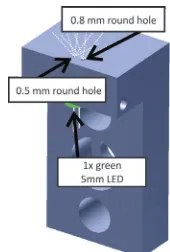
Fig. 4. Calibration coordinate system fixed in robot working space
of an L stand that has a 5 mm hole on the bottom side. It is meant for a 5 mm LED. For better contrast we have chosen a green LED. On the top side of the stand two small holes in the 5 mm LED area are drilled. The bigger hole has a diameter of 0.8 mm and the smaller one a diameter of 0.5 mm. These two holes or dots represent one axis of fixed coordinate system (Fig. 5) in robot working space. The larger dot represents the origin (O) of coordinate system and the smaller a dot
on the X axis of the coordinate system. Both dots are
separated by 3 mm.
Fig. 5. Threshold image of two LED dots with drawn coordinate system
2 THE VISUAL TOUCH-UP METHOD
The visual touch-up method is a non-contact version of a standard touch calibration method and can be used in many robot calibration areas. The non-contact method can be connected with contact method if the term of virtual pin is introduced (Fig. 6). Virtual pin is a virtual connection from the robot to the target position. The literature is very poor in the field of visual touch-up method used for robot calibration
purposes and only Watanabe et al. [19] published a
contemporary research article in this field, which was used as the basis for our approach. Watanabe et al. used a single camera attached on the robot end-effector. The calibration target object is a perfect circle with its center point drawn in the robot working space. The size of the circle is predefined and is used to define geometric relations, where the center point is the target point. The authors state that the drawbacks of this approach are unidentified camera-intrinsic parameters and the distortion of the lens that can both affect calculations.
Visual touch-up method can be used for purposes of robot new tool calibration, robot absolute accuracy calibration and also for calibration of several robots carried vision systems as in our case. The non-contact method can use several sensors for calibration procedures: from laser distance sensors based on
triangulation [22] and conoscopic holography [23],
inductive or capacitive sensors and especially video
cameras as Watanabe et al. is presenting. In our case we have chosen the video camera approach, because both on robot attached systems are vision based and also the planar robot movement simplifies the calibration procedures approach (Fig. 6). The reference objects of our visual touch-up approach are small round green dots presented in Figs. 4 and 5.
Fig. 6. Visual touch-up system represented on 3D model
3 IMPLEMENTED VISUAL TOUCH-UP METHOD CALIBRATIONS
As described in the previous sections, the measurement vision system is checked for accuracy and calibrated by using the calibration protectors. With the implementation of this system, the welding point (PX, PY) is defined in camera image coordinate system
C, independent in regard to any other coordinate
systems of the robot cell (Fig. 2). But to be able to
transform the welding point (PX, PY) from C in to the
robot reference coordinate system R and to position
the welding optics to the proper position (WPX, WPY) several coordinate systems need to be defined automatically via the visual touch-up method.
3.1 Robot Self-Calibration of the New Welding Laser Optics Tool
The robot can position the welding laser optics to the
calculated coordinates WPX and WPY if the welding
laser optics frame L regarding to the robot default
end E E is defined as a transformation TL
E or as a
predefined robot new tool (Fig. 7), also called tool center point (TCP). In production facilities this is frequently done by manually defining a new tool attached to the end of the robot with a special Epson wizard for manually defining new TCP‘s named as
ToolN (e.g. Tool1). This procedure requires a certain amount of time of at least a few minutes to be finished by the operator and is therefore too inconvenient for a quick recalibration and totally improper for high volume production line.
Fig. 7. The positioning of the welding laser optics according to the WPX, WPY welding point
In our system the robot makes fast movements that can shift attached equipment, or the operator accidentally hits the laser optics during maintenance of the robot cell. For these reasons an automatic tool calibration procedure for defining the center of
the welding laser as a new tool, called Tool1, was
developed.
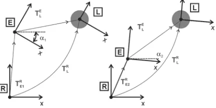
Fig. 8. Transformations for new TCP calculation
For the automatic tool calibration procedure a bigger LED dot from Fig. 5 is used. The calibration procedure requires positioning of the laser welding
optics L in the center of a reference point (bigger
dot), marked as a filled circle in Fig. 8, in two different robot configurations and can be described with Eq. (1)
where N is 1 and 2. To make all further figures
transparent, only the x axis of the coordinate frame is
marked and the z axis points out of the plane. The y
axis is set respectively to the right-hand coordinate system.
TL T T
R EN
R L
E
= ⋅ . (1)
In this calibration procedure the robot first moves the laser optics to the predefined position (EXN, EYN,
αN) in robot reference frame R, saved in the previous calibration procedure, where the center of the laser optics and the center of the reference point should align. The decision whether the welding laser optics center is aligned with the center of the reference point is made by the dedicated software by implementing a circular Hough transform [24] to [26] on the captured laser optics video camera image. The task of the Hough transform method is to search for objects of different shapes (lines, circles, ellipse) in an image by a voting approach in parameter space. Within this space the objects are gained as local maximum in an accumulator space.
Unlike in Watanabe et al. [19] where the error
between the reference point and the captured image point is calculated and used in further calculations, we implemented a simple step position controller to reduce the position error inside the predefined tolerance area of 0.05 mm if the movement is necessary. The movement of the robot is in steps of 0.015 mm in both planar axes. The tolerance area can be specified in millimeters because the width of the bigger dot is known and the result of the Hough transform is the radius of the circle in pixels. At this
point the current robot TCP position E is saved as a
new point (EXN, EYN, αN) for the next calibration attempt. With this information a new transformation
TEN
R (Eq. (2); N = 1) is set.
TEN
R =Rot z
(
)
⋅Trans E(
E)
N XN YN
,α , ,0 . (2)
In order to calculate the transformation TL
E
between the end of the robot (E) and welding laser optics (L) a second transformation is needed (Eq. (1);
N = 2). It defines the new configuration (Eq. (2);
N = 2) of the robot, pointing with the center of the
welding laser optics in the same, bigger LED reference point. The procedure is the same as described before, only the robot initial pose is different EXN, EYN, αN where N equals 2.
From the matrix in Eq. (3) only position
expressed as Eq. (4). Coordinates ELX and ELY
define the new TCP (saved as Tool1) representing the
welding laser optics center (L) relative to the end of the robot (E).
TL
E=Trans EL EL
(
)
X, Y,0 , (3)
EL E E
E E
X X X
Y Y
=
(
−)
⋅(
−)
+ +(
−)
⋅(
−)
1 2 1 2
1 2 1 2
cos cos
sin sin ,
α α
α α
EL E E
E E
Y Y Y
X X
=
(
−)
⋅(
−)
− −(
−)
⋅(
−)
1 2 1 2
1 2 1 2
cos cos
sin sin .
α α
α α (4)
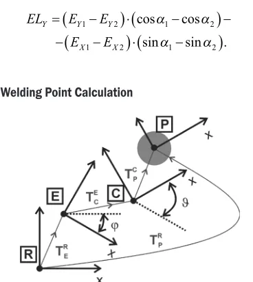
4.2 Welding Point Calculation
Fig. 9. Transformations for welding point calculation
Fig. 9 shows the homogenous transformation relations that are important for calculation of the
welding point in the reference robot frame R. The
welding point, marked as P, is determined in the
measurement camera frame C. This transformation
can be written as a homogenous transformation matrix (Eq. (5)) marked as with the same orientation as the
measurement camera frame C.
TP
C=Trans P P
(
)
X, Y,0 . (5)
The camera C is physically fixed in regard to the
robot end E described by the transformation TC
E (Eq.
(6)). This transformation is defined with the distance (ECX, ECY) from robot end frame E to the measuring
camera frame C and with a rotation angle ϑ around
the Z axis.
TC
E =Rot z
( )
⋅Trans EC EC(
)
X Y
,ϑ , ,0. (6)
The robot end frame E pose in robot reference
frame R can be written as homogenous
transformation TE
R (Eq. (7)) with parameters
(EX, EY, φ) read directly out of the robot controller as
Tool0 representing the bare end of the robot, based on ideal kinematic robot parameters.
TE
R=Rot z
( )
⋅Trans E E(
)
X Y
,ϕ , ,0 . (7)
The welding point position (WPX, WPY) is
calculated from measurement camera C position P
into the robot reference frame R by Eq. (8).
TP T T T
R E
R C
E P
C
= ⋅ ⋅ . (8) The welding point is a dot expressed as Eq. (9).
WP E EC P
EC P
WP E E
X X X X
Y Y
Y Y
= + ⋅ + ⋅
(
+)
− − ⋅ − ⋅(
+)
= +
cos cos
sin sin ,
ϕ ϕ ϑ
ϕ ϕ ϑ
C
C P
EC P
Y X
X X
⋅ + ⋅
(
+)
+ + ⋅ + ⋅(
+)
cos cos
sin sin .
ϕ ϕ ϑ
ϕ ϕ ϑ (9)
3.3 Defining the Measurement Camera
The welding point (WPX, WPY) position in robot
reference frame R is calculated by Eq. (8) where all
three transformations (TE
R, T C
E and T
P
C) must be
known. A great problem is definition of the
transformation TC
E, representing the pose of the
measurement camera frame C in the robot end frame
E. Just as the welding tool, the measurement camera
can also move slightly due to vibrations and fast movements of the robot. This is why we developed an automatic calibration procedure to define transformation TC
E.
To define transformation TC
E both green reference
LED points positions in the robot reference frame
must be known. At the end of the new tool (Tool1)
calibration procedure described earlier in the text the welding laser optics is already positioned in the center of the larger reference point with a diameter of 0.8 mm in Fig. 10 marked as a large shaded circle. Because the laser is defined as a new tool this position of the reference circle can be saved as point R1(R1X, R1Y) in the robot reference frame (Fig. 10a).
Fig. 10. Green LED dots position in reference frame; a) bigger dot used for tool calibration, b) smaller dot used for tool calibration
known (Fig. 10b). With the step position controller, described earlier in the text, the welding laser optics is positioned over the smaller reference point. Based on Tool1 the position of this reference point is saved as point R2(R2X, R2Y) in the robot reference frame.
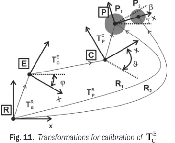
Points R1 and R2 represent (Fig. 5) the reference
coordinate system in robot reference frame, marked as in Fig. 11 and defined by Eq. (10), depending on robot kinematics and not representing the absolute accurate position.
Fig. 11. Transformations for calibration of TCE
TP
R=Rot z
( )
⋅Trans R R(
)
X Y
,γ 1 , 1 ,0 . (10)
To determine transformation TC
E, the position of
both green reference LED points in the measurement
camera frame C must be known. This procedure is
done by the robot moving the measurement camera in a predefined position where both reference points are visible by the measurement camera. The software then captures the image and determines the position of the reference points centers P1(P1X, P1Y) and P2(P2X, P2Y) in the measurement camera frame. With this
information transformation TP
C is defined as Eq. (11).
TP
C=Rot z
(
)
⋅Trans P P(
)
X Y
,β 1 , 1 ,0 . (11)
The situation in Fig. 11 is described by Eq. (8)
where transformation can be expressed as Eq. (12).
TC T T T
E E
R R
P C
=
( )
−1⋅ P ⋅( )
−1. (12)The transformation described by Eq. (12) and
Eq. (13) gives the orientation angle ϑ and position
coordinates ECX and ECY (Eq. 6) of the EC coordinate system.
EC RP E P
RP E P
X X X X
Y Y Y
=
(
−)
⋅ − ⋅(
+ −)
+ +(
−)
⋅ − ⋅ +cos cos
sin sin
ϕ β ϕ γ
ϕ β ϕ
1
1
(
−−)
=
(
−)
⋅ − ⋅(
+ −)
+ +(
−)
⋅ + ⋅γ
ϕ β ϕ γ
ϕ
,
cos cos
sin
EC RP E P
RP E P
Y Y Y Y
X X X
1
1 ssin
(
β ϕ γ+ −)
. (13)4 ROBOT CALIBRATION UNCERTAINTIES
The WP is defined by Eq. (9). This equation consists of several system variables, which all carry some uncertainty that accumulates into the final positional error.
Fig. 12. ECX error depending on Δβ and Δγ when Δφ is 0.005°
Table 1. EC transformation error estimation parameters
RPX= 270 mm ΔEX = 0.015 mm
RPY = 420 mm ΔEY = 0.015 mm
EX= –250 mm ΔRPX = 0.015 mm
EY= 360 mm ΔRPY = 0.015 mm
PX= 2 mm ΔPX = 0.1 mm
PY= 1 mm ΔPY = 0.1 mm
β = 90° Δφ = 0.005°
γ= 90° φ= 90°
The first variable is the pose of the robot end (EX, EY and φ) summed from joint angle, clearances
and length error [27]. Each contribution separately is
not given by robot manufacturer. The absolute error can not be estimated, but the relative error is the same as the robot repeatability specification for the first two planar joints, specified at ±0.015 mm. Next is the uncertainty of defining the welding point in camera
coordinate system (PX and PY). It is originating
from the measurement camera calibration tolerances defined at ±0.1 mm. In addition to the presented system variables, the most challenging task was to estimate the uncertainty of defining the pose of the camera coordinate system in regard to the robot end coordinate system (EC).
Before the robot cell was implemented in the production line and a proper calibration method was selected, the mathematical equations were used to estimate the error. For error estimation purposes
analysis result for Eq. (13), where in regard to 3D model robot cell parameters (Table 1) were included, is very poor. The maximal positional error of defining
the camera coordinate system C at the end of the
robot coordinate system E is from approximately
–6 mm to 6 mm, higher in X direction (Fig. 12) than in
Y direction (Fig. 13).
Fig. 13. ECY error depending on Δβ and Δγ when Δφ is 0.005°
The analysis showed that the angles included in calculations dominantly contribute to the absolute error. The predicted errors of calculation angles were
Δβ ≈ 1.9°, Δγ≈ 0.95° and Δφ ≈ 0.005°, all together contributing to the ϑ angle (≈±3°).
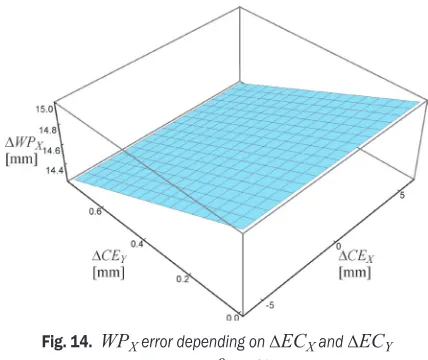
Fig. 14. WPX error depending on ΔECX and ΔECY
when Δϑis —3º
The camera coordinate system C position error
relative to the end of the robot coordinate system E
directly contributes (Eq. (9)) to the error of the laser (WP) in the robot coordinate system. Further analysis showed that the contribution is significant and the position error of laser welding poinn can be up to ±20 mm, far too much than the desired ±0.1 mm. Figs. 14 and 15 show the error of the laser (WP) if only the error of EC transformation is considered. Table
2 shows all other necessary calculation parameters.
In Fig. 14 the variables are ΔECX and ΔECY with
resulting error ΔWPX and in the Fig. 15 the variables
are ΔECX and Δϑ with resulting error ΔWPY.
Fig. 15. WPX error depending on ΔECX and Δϑ
when ΔECY is 0.76 mm
Table 2. WP transformation error estimation parameter; ≈ represents any value
EX=≈ mm ΔEX= 0 mm
EY=≈ mm ΔEY= 0 mm
ECX=75 mm ΔECX= 6 mm
ECY= –13 mm ΔECY= 0.18 mm
PX=2.5 mm ΔPX= 0 mm
PY=5 mm ΔPY= 0 mm
φ =90° Δφ = 0°
γ=90° Δγ= 3°
As presented, the literature declares the kinematic error as the main source of the absolute position error. However, the presented automatic calibration method enables to include all robot kinematic and measurement uncertainties into the final result
written as transformation matrix TC
E. This is possible
5 RESULTS FROM THE PRODUCTION LINE
All the manufacturing data for each protector in the robotic cell is stored into the database. In this section the manufacturing results for the whole year 2014 are presented and used for visual touch-up method statistical analysis.
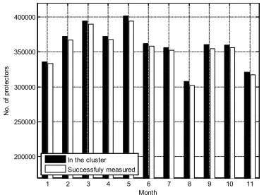
In 2014 a total number of 4,132,176 protectors were positioned into the rotary table clusters. In Fig. 16 the bars on the left represent the distribution of protectors throughout 2014. On average around 340,000 protectors are put into the clusters each month, thus 15,000 each day. The bars on the right show the number of protectors processed with the robotic system.
1 2 3 4 5 6 7 8 9 10 11 200000
250000 300000 350000 400000
Month
N
o.
of
pr
ot
ec
tor
s
In the cluster Successfuly measured
Fig. 16. All protectors set in the clusters and processed with the robotic system in the year 2014
It can be seen that some of the protectors are not processed by the robotic system due to many reasons arising from previous production stages. A sum of 50,608 protectors of the total number were not processed by the robot cell, which is 1.22 % (2.5 manufacturing days).
The total number of successfully analyzed and welded protectors in 2014 was 4,072,536. It is worth mentioning that in the case of unsuccessful measurement or welding (robotic system reports an error), these protectors are put back into the rotary table clusters at the end of the production day. In such cases, the system is not able to detect which protector was put back into the cluster. For this reason also the repeatedly measured protectors are included in the total number of successfully measured and welded protectors.
5.1 Welding Point Distribution
In addition to measure distances A and B, the task of the system is also determination of coordinates for
the welding point defined in the measurement camera frame. The welding point is calculated by combining a fixed offset (dX, dY) and the welding point frame (W) position (WPX and WPY) (Fig. 2).
Fig. 17. Welding point position in 2014
2.55 2.6 2.65 2.7 2.75 2.8 2.85 2.9 2.95 3 0
1 2 3 4 5 6
x 105
X welding position (mm)
N
o.
of
pr
ot
ec
tor
s
Fig. 18. Distribution of the welding point X in 2014; each bar represents 10 µm
4 4.2 4.4 4.6 4.8 5 5.2 5.4 5.6 0
1 2 3 4 5 6 7 8 9
x 104
Y welding position (mm)
N
o.
of
pr
ot
ec
tor
s
Fig. 19. Distribution of the welding point Y in 2014; each bar represents 10 µm
coordinate system. The mean position of X coordinate
is 2.74 mm and 4.91 mm in Y direction, marked
with a cross (Fig. 17). The maximal width error in
X direction is 0.32 mm and 1.56 mm in Y direction.
These measurement results from the production line prove that the detection of welding point for each individual protector is a must, otherwise the set screw and the bimetal are not welded properly together. In
Fig. 19 the reader can see two peaks in Y distribution
arising from the fact that two different suppliers supply the company with protector ceramics. From there the dimensions of the ceramics can slightly differ, resulting in different bimetal vertical position.
5.2 Measurement System Calibration Statistics
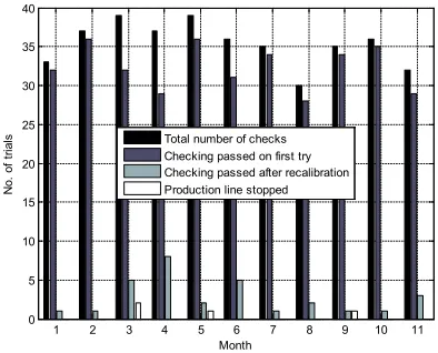
As mentioned earlier in the text, the auto-checking and auto-calibration of the transformation of the measurement system accuracy is scheduled every 10,000 protectors being processed. The measurement system has major influence on all calibration procedures between measurement and welding system. For this reason also the measurement system calibration results from production data are presented.
1 2 3 4 5 6 7 8 9 10 11 0
5 10 15 20 25 30 35 40
Month
N
o.
of
tr
ial
s Total number of checks Checking passed on first try Checking passed after recalibration Production line stopped
Fig. 20. Measurement accuracy calibration statistics for year 2014
Fig. 20 confirms well verification interval of measurement system auto-check and auto-calibration cycles that is 1.5 times per day or on average 34 times per month. The database data reveals in most trials (31 per month out of 34) no need for an auto-calibration procedure. From Fig. 20 can also be verified, that some of the checking trials failed, in such case recalibration is needed. After the measurement system is verified again for measurement accuracy, in most cases the checking has been successful. In March, May and September, the checking after the
recalibration of the measuring system failed and for this reason the production line stopped. The reason was primarily in the dust that came into the area of cell containing the calibration protectors. After cleaning all the area, the measurement system recalibration was started manually, consequently passed the test without a problem.
5.3 Measurement and Welding System Calibration Statistics
If auto-checking or auto-calibration procedure of the measuring system is passed, then the procedure for both auto-checking of the measurement and welding system transformations is started. In 2014, the transformations were checked on average 34 times per month (Fig. 21). This number is the same as for the measurement accuracy checking. The number of successful transformation checks is 31 per month. The biggest difference in the number of recalibration trials is observed in months when the majority of transformation recalibration procedures were started i.e. in June and July, 15 and 11 times respectively. From the information available from the database it is impossible to recognize a good reason for a high number of recalibration trials. It is encouraging that the number of instances where the production line stops is low. In these cases, the biggest problem was found to be the dust that fills the reference point holes. This happens despite the air stream constantly flowing through the holes from bottom to top.
1 2 3 4 5 6 7 8 9 10 11 0
5 10 15 20 25 30 35 40
Month
N
o.
of
tr
ial
s Total number of checks Checking passed on first try Checking passed after recalibration Production line stopped
Fig. 21. Measurement and welding calibration statistics for the year 2014
6 DISCUSSION
product called the protector. The implemented robot system uses very robust automatic vision touch-up method for defining transformations from local to the global coordinate systems present in the robot system. All the transformations are used for calculation of the welding point, defined in measurement video camera coordinate system into the global robot coordinate system.
Very high measurement requirements were satisfied by using a high resolution camera, high-quality optics, adequate algorithm approach and in addition implementing auto-checking / calibration procedure of the measuring system. For maintaining measurement accuracy, all three reference protectors were in advance measured with a certified profile projector machine, type Mitutoyo PV500.
In addition to the camera measurement system checking/calibration procedures also the auto-checking/calibration procedure for transformation between the measurement and welding system is quick and reliable. The installed approach as a visual touch-up method seems to be the right solution for our application. This claim is confirmed with the final results showing the perfection of task in the production facilities.
In 2014 in a few checking instances (33) the transformation recalibration was needed and was in most cases also successful. On average 31 transformation checks per month are started and usually there is no need to perform the entire transformation recalibration procedure again.
With implementation of proposed visual touch-up method, the errors arising from real robot kinematics deviations in regard to inbuilt ideal kinematic model, welding tool calibration error, measurement system error, lens distortion error and camera intrinsic parameters error are all included in calculated transformation TC
E, that is defining the pose of the
measurement camera coordinate system in regard to the robot end coordinate system. The common point of the measurement and welding system is an external fixed reference coordinate system. This reference object is implemented as two small dots with different but known diameter sizes and illuminated with a single green LED with known diameters. The benefits of using proposed visual touch-up calibration system are:
• the system is cheap,
• the space occupied in the robot cell is very small, • simple to use,
• easy to maintain,
• short time of production line stop for any reason,
• the equipment is used also for other tasks in the robot cell,
• the long-period of maintenance free operation in the production shows a high robustness of the system.
In the production line the welding operation is frequent, leading to a lot of black dust accumulating in the robot working area. The long-time usage of the system revealed that the dust can cause problems when the auto-checking/calibration of measurement and welding system transformations is performed in spite of protection housing. The green reference LED points are not covered, but the dust problem is alleviated with air stream blowing through a separate hole connected with the green reference LED holes. This solution is not 100 % efficient and the operator needs to occasionally clean both small holes manually.
One of the draw-backs of the proposed calibration system is the time that is needed to complete all necessary auto-checking/calibration procedures. For auto-checking of the measurement system 4 seconds are needed and for auto-checking of measurement and welding systems transformations 10 seconds are needed. This is approximately the time to manufacture 6 protectors and in one year approximately 2400 protectors less are manufactured. The total time for full auto-calibration procedure of measurement and measurement with welding system is cca. 40 seconds. In this time 18 protectors could be manufactured.
In one year this leads to a 6670 (≈0.2 %) smaller
production of protectors only due to the necessary calibration procedures. The presented calculations force us and also the operational workers to maintain the system as clean as possible for continuous manufacturing of protectors.
7 CONCLUSIONS
A robust robot measurement and laser welding system for protector supervision was developed with integrated robust visual touch-up auto-calibration method. The complexity of the robotic system brought many challenges that needed to be solved, especially in the field of automatic calibration procedures and methods used behind these procedures.
8 REFERENCES
[1] Grigoriev, S., Starkov, V., Gorin, N., Krajnik, P., Kopac, J. (2014). Creep-feed grinding: An overview of kinematics, parameters
and effects on process efficiency. Strojniški vestnik - Journal
of Mechanical Engineering, vol. 60, no. 4, p. 213-220,
DOI:10.5545/sv-jme.2013.1547.
[2] Erden, M.S., Marič, B. (2011). Assisting manual welding with
robot. Robotics and Computer-Integrated Manufacturing, vol.
4, no. 27, p. 818-828, DOI:10.1016/j.rcim.2011.01.003.
[3] Pellegrinelli,, S., Pedrocchi, N., Lolinari-Tosatti, L., Fischer, A., Tolio, T. (2014). Multi-robot spot-welding cell design: Problem
formalization and proposed architecture. Procedia CIRP, vol.
21, p. 324-329, DOI:10.1016/j.procir.2014.03.164.
[4] Carlson, J.S., Spensieri, D., Wärmefjord, K., Segeborn, J., Söderberg, R. (2014). Minimizing dimensional variation and robot traveling time in welding stations. Procedia CIRP, vol. 23,
p. 77-82, DOI:10.1016/j.procir.2014.03.199.
[5] Tsai, M.J., Lee, H.-W., Ann, N.-J. (2011). Machine vision based
path planning for a robotic golf club head welding system. Robotics and Computer-Integrated Manufacturing, vol. 27, no.
4, p. 843-849, DOI:10.1016/j.rcim.2011.01.005.
[6] Lee, D., Ku, N., Kim, T.-W., Kim, J., Lee, K.-Y., Son, Y.-S. (2011). Development and application of an intelligent welding robot
system for shipbuilding. Robotics and Computer-Integrated
Manufacturing, vol. 27, no. 2, p. 377-388 DOI:10.1016/j.
rcim.2010.08.006.
[7] Emmelmann, C., Schenk, K., Wollnack, J., Kirchhoff, M.
(2011). High-precision calibration of a weld-on-the-fly-system. Physics Procedia, vol. 12, part A, p. 739-743, DOI:10.1016/j.
phpro.2011.03.092.
[8] Traslosheros, A., Sebastián, J.M., Torrijos, J., Carelli, R. Castillo, E. (2013). An inexpensive method for kinematic calibration of a parallel robot by using one hand-held camera as main
sensor. Sensors, vol. 13, no. 8, p. 9941-9965, DOI:10.3390/
s130809941.
[9] Santolaria, J., Ginés, M. (2013). Uncertainty estimation in robot kinematic calibration. Robotics and Computer-Integrated Manufacturing, vol. 29, no. 2, p. 370-384, DOI:10.1016/j.
rcim.2012.09.007.
[10] Nubiola, A., Bonev, I.A. (2014). Absolute robot calibration with
a single telescoping ballbar. Precision Engineering, vol. 38,no.
3, p. 472-480, DOI:10.1016/j.precisioneng.2014.01.001.
[11] Ravikumar, S., Ramachandran, K.I., Sugumaran, V. (2011).
Machine learning approach for automated visual inspection of
machine components. Expert Systems with Applications, vol.
38, no. 4, p. 3260-3266, DOI:10.1016/j.eswa.2010.09.012.
[12] Yin, S., Guo, Y., Ren, Y., Zhu, J., Yang, S., Ye, S. (2014). A novel TCF calibration method for robotic visual measurement
system. Optik - International Journal for Light and Electron
Optics, vol. 125, no 23, p. 6920-6925, DOI:10.1016/j. ijleo.2014.08.049.
[13] Motta, J.M.S.T., de Carvalho, G.C., McMaster, R.S. (2001). Robot calibration using a 3D vision-based measurement
system with a single camera. Robotics and
Computer-Integrated Manufacturing, vol. 17, no. 6, p. 487-497,
DOI:10.1016/S0736-5845(01)00024-2.
[14] Švaco, M., Šekoranja, B., Šuligoj, F., Jerbić, B. (2014). Calibration of an industrial robot using a stereo vision system. Procedia Engineering, vol. 69, p. 459-463, DOI:10.1016/j.
proeng.2014.03.012.
[15] Meng, Y., Zhuang, H. (2007). Autonomous robot calibration
using vision technology. Robotics and Computer-Integrated
Manufacturing, vol. 23, no. 4, p. 436-446, DOI:10.1016/j.
rcim.2006.05.002.
[16] Du, G., Zhang, P. (2013). Online robot calibration based on
vision measurement. Robotics and Computer-Integrated
Manufacturing, vol. 29, no. 6, p. 484-492, DOI:10.1016/j.
rcim.2013.05.003.
[17] Nubiola, A., Bonev, I.A. (2013). Absolute calibration of an ABB
IRB 1600 robot using a laser tracker. Robotics and Computer-Integrated Manufacturing, vol. 29, no. 1, p. 236-245,
DOI:10.1016/j.rcim.2012.06.004.
[18] Espiau, B., Chaumette, F., Rives, P. (1992). A new approach to
visual servoing in robotics. IEEE Transactions on Robotics and
Automation, vol. 8, no. 3, p. 313-326, DOI:10.1109/70.143350.
[19] Watanabe, A., Sakakibara, S., Ban, K., Yamada, M. Shen, G.
Arai, T. (2006). A kinematic calibration method for industrial robots using autonomous visual measurement, CIRP Annals - Manufacturing Technology, vol. 55, no. 1, p. 1-6, DOI:10.1016/
S0007-8506(07)60353-9.
[20] Du, G., Zhang, P., Li, D. (2015). Online robot calibration
based on hybrid sensors using Kalman filters. Robotics and
Computer-Integrated Manufacturing, vol. 31, p. 91-100,
DOI:10.1016/j.rcim.2014.08.002.
[21] Watanabe, A., Sakakibara, S., Ban, K., Yamada, M., Shen, G., Arai, T. (2005). Autonomous Visual measurement for accurate setting of workpieces in robotic cells. CIRP Annals-Manufacturing Technology, vol. 54, no. 1, p. 13-18,
DOI:10.1016/S0007-8506(07)60039-0.
[22] Tang, G.-r., Liu, L.-s. (1993). Robot calibration using a single laser displacement meter. Mechatronics, vol. 3, no. 4, p.
503-516, DOI:10.1016/0957-4158(93)90020-3.
[23] Álvarez, I., Enguita, J.M., Frade, M., Marina, J., Ojea, G. (2009). On-line metrology with conoscopic holography: Beyond triangulation. Sensors, vol. 9, no. 9, p. 7021-7037,
DOI:10.3390/s90907021.
[24] Pei, S.-C., Horng, J.-H. (1995). Circular arc detection based on Hough transform. Pattern Recognition Letters, vol. 16, no. 6,
p. 615-625, DOI:10.1016/0167-8655(95)80007-G.
[25] Mukhopadhyay, P., Chaudhuri, B. B. (2015). A survey of Hough
transform. Pattern Recognition, vol. 48, no. 3, p. 993-1010,
DOI:10.1016/j.patcog.2014.08.027.
[26] Munib, Q., Habeeb, M., Takruri, B., Al-Malik, H.A. (2007). American sign language (ASL) recognition based on
Hough transform and neural networks. Expert Systems
with Applications, vol. 32, no. 1, p. 24-37, DOI:10.1016/j.
eswa.2005.11.018.
[27] Zhu, J., Ting, K.-L. (2000). Uncertainty analysis of planar and
spatial robots with joint clearances. Mechanism and Machine
Theory, vol. 35, no. 9, p. 1239-1256,
DOI:10.1016/S0094-114X(99)00076-2.
[28] Godina, A., Acko, B. (2014). Measurement uncertainty analysis
for calibration of gauge blocks. Procedia Engineering, vol. 69,