Author name / JHMTR 00 (2013) 000–000 29
Introduction
Nowadays, the use of renewable electricity in urban areas has become very popular [1-2]. According to the statistics, the growth in the use of local off-grid electricity has grown a lot in recent years, indicating an increasing demand for such type of electrical energy generation [3]. To produce electrical energy in remote areas, use of primary energy sources such as fossil fuels for diesel generator systems and combined heat and power (CHP) systems, wind energy for wind power generation systems (WPGS) and solar energy for solar power generation systems (SPGS), are all economical and commonly used. Among all of these, solar energy can be the best option for power generation in remote areas, because solar power systems have simpler processes for maintenance which is so important for remote areas.
Considering that the electricity produced by the photovoltaic panels is DC and most electric power consumers use alternating current (AC), power electronics should be used to convert DC power to AC. Different structures are employed for such purposes; among which a two-level three-phase inverter has simplicity and, at the same time, it gives a high utilization for low powers. If a three-phase two-level inverter is switched by the SPWMa method, the output has many harmonics which requires the use of a filter unit [4-8]. The three common types are L, LC, and LCL.
In the L structure, as shown in Fig.(1-a), an inductor is used between the inverter and the grid. Because of the fact that it is a first-order system, this structure has a low downgrade capability. To overcome to this problem, we need to increase the
a
Sinusoidal Pulse-Width Modulation
Click here, type the title of your paper, Capitalize first letter of each words
First Author
a, Second Author
b,*aFirst affiliation, Address, City and Postcode, Country
b
Second affiliation, Address, City and Postcode, Country
Journal of Solar Energy Research Vol3 No 1 (2018) 29-33
A B S T R A C T
Click here and insert your abstract text. Click here and insert your abstract text. Click here and insert your abstract text. Click here and insert your abstract text. Click here and insert your abstract text. Click here and insert your abstract text. Click here and insert your abstract text. Click here and insert your abstract text. Click here and insert your abstract text. Click here and insert your abstract text. Click here and insert your abstract text. Click here and insert your abstract text. Click here and insert your abstract text. Click here and insert your abstract text. Click here and insert your abstract text. Click here and insert your abstract text. Click here and insert your abstract text. Click here and insert your abstract text. Click here and insert your abstract text. Click here and insert your abstract text. Click here and insert your abstract text Click here and insert your abstract text Click here and insert your abstract text Click here and insert your abstract text Click here and insert your abstract text Click here and insert your abstract text Click here and insert your abst
© 2013Published by University of Tehran Press. All rights reserved.
ARTICLE INFO Received:
Received in revised form: Accepted:
Available online:
Keywords: Type 3-6 keywords here,
separated by semicolons ;
An LCL Filter Design for Three-Phase Off-Grid PV Inverters
M.K. Javid
, F.Barati
*Division of Energy, Materials & Energy Research Centre (MERC), Kara j, Iran Email: [email protected]
Journal of Solar Energy Research (JSER)
Journal homepage: www.jser.ut.ac.ir
A B S T R A C T
Nowadays, the use of renewable electricity in urban outback areas has become very popular. According to the statistics, the growth in the use of local off-grid electricity has grown a lot in recent years, indicating an increasing need for this type of electrical energy. According to the fact that electrical consumers are often designed to work with alternating current, the production of electricity must have a sinusoidal waveform and, of course, within the standard limits for harmonics. Therefore, in the case of utilizing off-grid renewable sources, a standardized voltage waveform should be generated. It is achieved by employing an output filter unit. In this paper, by presenting a novel method for the LCL filter design, the output voltage and current are evaluated for a two-level three-phase inverter. The simulated and experimental results confirm the excellent performance of the designed filter.
© 2018 Published by University of Tehran Press. All rights reserved.
ARTICLE INFO
Received: 27 Oct 2017 Received in revised form: 14 Nov 2017
Accepted: 17 Nov 2017 Available online: 20 Nov 2017
Keywords: Solar Electricity; Off-Grid Inverters; Filtering Unit; LCL Filter;
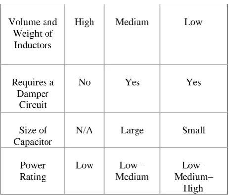
switching frequency. This will increase the switching losses in the converter, so it's not advisable to do so. Also, increasing the capacity of the inductance can increase the severity of the weakening, but this strategy causes an increase in Electromagnetic Interferences (EMI). Therefore, this structure is not a good solution for harmonics reductions. The LC structure, as seen in Fig.(1-b), consists of an inductor and a capacitor which results in a second-order system. It has a better attenuation than the L structure, but still needs a large inductance. In addition, a relatively large capacitor in this structure is needed. This structure requires a damper circuit to prevent resonances in the filter unit. The structure of the LCL filter, as seen in Fig.(1-c), creates a third-order system, so it performs well in the attenuation of the high-order harmonics. In order to avoid the resonances in this structure, a damper circuit is used. Different damping structures are already employed [9-11]. In this paper, a simple damping structure which includes a series resistance with the filter capacitor is used. In Table 1, the comparison between the three filters types is discussed. With respect to the advantages of the LCL structure, this structure is selected and assess in this article.
Nowadays, strong simulations tools such as
Matlab/Simulink and PSCAD/EMTDC are
available which can predict the behaviour of power electronics systems accurately. They can perform as design tools; instead of the conventional design approaches which are mainly based on analytical expressions. In this paper, we effectively employed simulations in the design procedure of LCL filter [12].
(a) (b)
(c)
Figure 1. L, LC, and LCL topologies
Table 1. Comparison between L, LC, and LCL filters
LCL LC
L Filter Type
Low Relatively
Low Very
High Switching
Frequency
Low Medium
High Volume and
Weight of Inductors
Yes Yes
No Requires a
Damper Circuit
Small Large
N/A Size of
Capacitor
Low– Medium–
High Low –
Medium Low
Power Rating
2. Proposed approach for LCL filter design
To start the design, we start from deriving the transfer function of the inverter output voltage to the current injected into the network.
( ) ( )( ) (1)
With respect to the effect of the damper resistance in the filter and the resistance of the inductors, the transfer function is written as follows:
( ) (2)
Here, Zi is the impedance connected to the inverter, Zf is the parallel impedance of the filter, and Zg is the impedance connected to the network. If the resistance of the inductors is ignored and the damper circuit is considered a series resistance with the capacitor, the transfer function is:
( )
( ) ( ) (3) This is a third-order transfer function that leads to a strong suppression of high-order harmonics. In Fig.2, the LCL structure is represented with a damping circuit.
Figure 2. LCL filter with damping resistor
Table 2: Input & output values of proposed flowchart for filter design
Inputs Pn = 5000 Watts
fsw = 10000 Hz fg = 50 Hz Vph = 230 Volts Vdc = 750 Volts
31 Li = 4.7 mH
Lg = 2.3 mH Cf = 2.5 uF
Rd = 10 𝛺
In order to design the LCL filter, the values of the phase voltage, switching frequency, network frequency, nominal active three-phase power and the DC link voltage are required. The filter design process is as follows.
Table 3: Final values of proposed filter design approach
Outputs Li = 0.8 mH Lg = 0.5 mH Cf = 4.7 uF
Rd = 1 𝛺
The design flowchart is shown in Appendix. We present the design for a 5kW inverter based on the flowchart and by employing the simulations in Matlab/Simulink. Considering the flowchart, the input and output values are as in Table2.
By employing the simulation tool, output values result in a THDi = 2%. According to the std. IEEE519-2014 [13], the injected current to grid total harmonics distortions, THDi , can be increased up to 5% . Therefore the values of filter can be chosen to reduce weight and volume of filter to control mechanical stresses on printed circuit board and also EMI. Generally, we are interested to reduce inductors sizes [14, 15]:
- To reduce eddy and hysteresis losses. - To reduce copper losses.
- To reduce Electromagnetic Interference. - To increase active and reactive power
exchange between solar power plant and utility grid.
With regards to the frequency analysis, it is concluded that:
- By decreasing the values of inductors, the THD of voltage and current decreases. - By decreasing the value of capacitor, the
THD of voltage and current decreases. - By increasing the value of the damping
resistance, the THD of voltage and current increases.
According to the above statements, the goal is the reduction of inductances and resistance. Also, the value of capacitance must be in the standard range. In this step of design, with the help of simulation tool, optimized values for filter parameters are obtained as in Table 3.
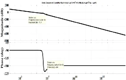
Based on the obtained values, the THD of output voltage and current is less than 5%. This yields to observe standard limits and achieve the goals. For the obtained transfer function and based on the final values for filter parameters, the Bode diagram is
drawn as in Fig.3. Based on this diagram, it can be concluded that:
- Good performance of filter unit in high-order harmonics suppression is achieved. - In low frequencies, where the fundamental
frequency is located, filter performs such as an inductance. In the other words, the parallel branch can be considered as open-circuited.
- The filter performance, with respect to the phase-margin and gain-margin concepts, is stable and therefore, the damping circuit has the desired behavior.
3. Simulation Results
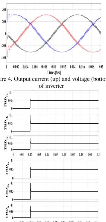
According to filter parameters obtained in the previous section, here THDi & THDv and their wave-forms are presented. As shown in Fig.4, and Fig.5, the peak instantaneous voltage and current are exactly equal to 325 volts and 10.25 amperes, respectively leading to:
(4) Also for the case of THD, it is visible that the standard limits are met.
Figure 4. Output current (up) and voltage (bottom) of inverter
Figure 5. THDv (up) and THDi(bottom)
4. Experimental Results
To implement the simulated circuit and to have experimental assessment of proposed method, a 5 KW inverter is designed and implemented. This inverter is shown in Figure 6. In this figure, we have:
1. Osilloscope
2. Three-phase miniature fuse 3. Multi-meter
4. DC link Capacitance
5. Inverter Board With LCL filter 6. Microcontroller
7. Power Supply
In order to test the designed filter in experiments, three 220 V, 200W lamps are considered as the phase load. In Fig.7, three-phase voltage and current at the output of inverter is shown confirming the excellent performance of filter in attenuating harmonics produced by the inverter.
Figure 6. Experimental set-up 5. Conclusions
In this article, a novel method for the LCL filter design is proposed. The method employs both of the analytical as well as simulation tools leading to optimum values for parameters of filter. Based on the simulation and experimental results, the proposed approach for LCL filter design can meet the standard limits at the optimum size of filter parameters.
Figure 7. Experimental results
References
[1] Ariel Bergmann, Sergio Colombo, Nick Hanley, Rural versus urban preferences for renewable energy developments, In Ecological Economics, Volume 65, Issue 3, 2008, Pages 616-625.
[2] Bruce N. Stram, Key challenges to expanding renewable energy, In Energy Policy, Volume 96, 2016, Pages 728-734
[3] A.S. Bahaj, P.A.B. James, Urban energy generation: The added value of photovoltaics in social housing, In Renewable and Sustainable Energy Reviews, Volume 11, Issue 9, 2007, Pages 2121-2136.
[4] M. A. Elsaharty, Passive L and LCL filter design method for grid-connected inverters, Innovative Smart Grid Technologies - Asia (ISGT Asia),4102 IEEE, Kuala Lumpur, 2014, pp. 13-18.
33
and Exposition (APEC), 2014 Twenty-Ninth Annual IEEE. IEEE, 2014.
[6] Huang, Min, et al. Step by step design of a high order power filter for three-phase three-wire grid-connected inverter in renewable energy system. Power Electronics for Distributed Generation Systems (PEDG), 2013 4th IEEE International Symposium on. IEEE, 2013.
[7] Chakraborty, Sudipta, Bill Kramer, and Benjamin Kroposki. A review of power electronics interfaces for distributed energy systems towards achieving low-cost modular design. Renewable and Sustainable Energy Reviews 13.9 (2009): 2323-2335.
[8] Paulino, Hendriks Delesposte, Paulo José Mello Menegáz, and Domingos Sávio Lyrio Simonetti. A review of the main inverter topologies applied on the integration of renewable energy resources to the grid. Power Electronics Conference (COBEP), 2011 Brazilian. IEEE, 2011. [9] L. Hassaine, E. OLias, J. Quintero, V. Salas, Overview of power inverter topologies and control structures for grid connected photovoltaic systems, Renewable and Sustainable Energy Reviews, Volume 30, February 2014, Pages 796-807. [10] Mehmet Büyük, Adnan Tan, Mehmet Tümay, K. Çağatay Bayındır, Topologies, generalized
designs, passive and active damping methods of switching ripple filters for voltage source inverter: A comprehensive review, Renewable and Sustainable Energy Reviews, Volume 62, September 2016, Pages 46-69.
[11] M. Sanatkar-Chayjani, M. Monfared, Design of LCL and LLCL filters for single-phase grid connected converters, IET Power Electronics, Volume 9, Number 9, 2016, Pages 1971-1978. [12] R.A.Dougal, Simulation methods for design of networked power electronics and information systems, Technical Report, 2014.
[13] IEEE519-2014, Recommended practice and requirements for harmonic control in electric power systems.
[14] Y. Liu, Jianchun Peng, Guibin Wang, Huaizhi Wang, K. Y. See, THD and EMI performance study of foil-wound inductor of LCL filter for high power density converter, IEEE IPEMC-ECCE Asia, 2016, Pages 3467-3471.
[15] M.I.Hamid, A.Jusoh, Reduction of waveform distortion in grid-injection current from single-phase utility interactive PV-inverter, Energy Conversion and Management, Volume 85, 2014, Pages 212-226.
Appendix
Start
ωmin < ωres < ωmax
Stop
No
Yes Pb - Pn Zb - ( 3 Vph)^2/Pb
Cb - 1/(2π×fg×Zb)
Imax - ( 2×Pb)/(3×Vph) Cf - 0.025 Cb ΔImax - 0.2 Imax Li - Vdc/(6×fsw×ΔImax )
Lg - γ × Li
ω res- ((Li+Lg)/(Li×Lg×Cf)) ωmin - 10 × ωg ωmax - 0.5 ×ωsw
Select new γ
Pn , Vph, Vdc , fsw , fg
γ - 0.5