Available online:https://edupediapublications.org/journals/index.php/IJR/ P a g e | 1642
An Efficient Low-Power Programmable PRPG with
Test Compression Capabilities
K. Satya Manuja, Dept of ECE
Abstract— This paper describes a low-power (LP) program-mable generator capable of producing pseudorandom t est p at -t erns wit h
desired toggling levels and enhanced fault coverage gradient compared with the best-to-date built-in self-test (BIST)-based pseudorandom test
p attern generators. It is comprised of a linear finite state machine (a linear feedback shift register or a ring generator) driving an app rop riat e
p hase shifter, and it comes with a number of features allowing this device to produce binary sequences with preselected toggl ing (PREST O)
act ivity. We introduce a method to automatically select several controls of the generator offering easy and precise tuning. The same technique
is subsequently employed to deterministically guide the generator toward test sequences with improved fault-coverage-to-pattern-count ratios.
Furthermore, this paper proposes an LP test compression method that allows shaping the test power envelope in a fully predictable, accurat e,
and flexible fashion by adapting the PRESTO-based logic BIST (LBIST) infrastructure. The proposed hybrid scheme efficient ly combines
t est compression with LBIST, where both techniques can work synergistically to deliver high quality tests. Experimental results obtained for
indust rial designs illust rat e t he feasibilit y of t he p rop ose d t est schemes and are rep ort ed herein.
Index Terms— Built-in self-test (BIST), low-power (LP) test,pseudorandom t est p at t ern generat ors (PRPGs), t est dat a volume comp ression.
I. INTRODUCTION
A
LTHOUGH over the next years, the primary objective of manufacturing test will remain essentially the same— to ensure reliable and high quality semiconductor products — conditions and consequently also test solutions may undergo a significant evolution. The semiconductor technology, design characteristics, and the design process are among the key factors that will impact this evolution. With new types of defects that one will have to consider to provide the desired test quality for the next technology nodes such as 3-D, it is appro-priate to pose the question of what matching design-for-test (DFT) methods will need to be deployed. Test compression,introduced a decade ago, has quickly become the main stream DFT methodology. However, it is unclear whether test com-pression will be capable of coping with the rapid rate of technological changes over the next decade. Interestingly,logic built-in self-test (LBIST), originally developed for board, sys-tem, and in-field test, is now gaining acceptance for production test as it provides very robust DFT and is used increasingly often with test compression. This hybrid approach seems to be the next logical evolutionary step in DFT. It has potential for improved test quality; it may augment the abilities to run at-speed power aware tests, and it can reduce the cost of manufacturing test while preserving all LBIST and scan compression advantages.
Available online:https://edupediapublications.org/journals/index.php/IJR/ P a g e | 1643 or a device malfunction because of timing failures following a
significant circuit delay increase, for example. Abnormal switching activity may also cause fully functional chips to fail during testing because of phenomena, such as IR-drop, crosstalk, or d i/d t problem.
Numerous schemes for power reduction during scan testing have been devised [14]. Among them, there are solutions specifically proposed for BIST to keep the average and peak power below a given threshold. For example, the test power can be reduced by preventing transitions at memory elements from propagating to combinational logic during scan shift. This is achieved by inserting gating logic between scan cell outputs and logic they drive [9], [19]. During normal opera-tions and capture, this logic remains transparent. Gated scan cells are also proposed in [3] and [56]. A synergistic test power reduction method of [57] uses available on-chip clock gating circuitry to selectively block scan chains while employing test scheduling and planning to further decrease BIST power in the Cell processor. A test vector inhibiting scheme of [11] masks test patterns generated by an LFSR as not all produced vectors, often very lengthy, detect faults. Elimination of such tests can reduce switching activity with no impact on fault coverage.
The advent of low-transition test pattern generators has added a new dimension to power aware BIST solu-tions [5], [32], [42]. For example, a device presented in [49] employs an LFSR to feed scan chains through biasing logic and T-type flip-flop. Since this flip-flop holds the previous value until its input is asserted, the same value is repeatedly scanned into scan chains until the value at the output of biasing logic (e.g., a k-input AND gate) becomes 1. Depending on k, one can
significantly reduce the number of transitions occurring at the scan chain inputs. A dual-speed LFSR of [48] consists of two LFSRs driven by normal and slow clocks, respectively. The switching activity is reduced at the circuit inputs connected to the slow-speed LFSR, while the whole scheme still ensures satisfactory fault coverage. Mask patterns mitigate the switching activity in LFSR-produced patterns as shown in [41], whereas a bit swapping of [1] achieves the same goal at the primary inputs of CUT. A gated LFSR clock of [12] allows activating only half of LFSR stages at a time. It cuts power consumption as only half of the circuit inputs change every cycle. Combining the low transition generator of [49] (handling easy-to-detect faults) with a 3-weight pseudoran-dom test pattern generator (PRPG) (detecting ranpseudoran-dom pattern resistant faults) can also reduce BIST switching activity, as demonstrated in [47]. The schemes of [25], [36], and [43] suppress transitions in LFSR-generated sequences by either statistical monitoring or injecting intermediate and highly correlated patterns. Finally, a random single-input change generator can produce low power patterns in a parallel BIST environment, as shown in [13].
As the BIST power consumption can easily exceed the maximum
ratings when testing at speed, scan patterns must be shifted at a
programmable low speed, and only the last few cycles and the
capture cycle are applied at the maximum fre-quency. In the
burst-mode approach presented in [35], typically five consecutive
clock cycles are used. The first four cycles serve shifting
purposes, whereas the last one is designated for capture. The
objective is to stabilize the power supply before the last shift
and capture pulses are applied, which are critical for at-speed
tests. To reduce the voltage droop related to a higher circuit
activity, a burst clock controller slows down s ome of the shift
cycles. It allows a gradual increase of the circuit activity,
thereby reducing the d i/d t effect. The controller can gate the
shift clocks, depending on the needs for gradually warming up
of the circuit. Low power (LP) test compression schemes [28],
[33], [41], [53] adapt again LFSR reseeding to reduce scan-in
transitions as the low fill rates make it possible to deliver
identical test data to scan chains for a number of shift cycles
directly from the decompressor, thereby reducing the number
of transitions.
Available online:https://edupediapublications.org/journals/index.php/IJR/ P a g e | 1644 Section III presents all architectural details of its structure
with a brief discussion of the generator’s abilities to produce patterns with various toggling rates. Section IV demonstrates how the PRESTO generator can be programmed in order to yield pseudorandom test patterns of desired switching activity. Experiments validating this technique are discussed in Section V. In addition, a method to achieve higher BIST fault coverage
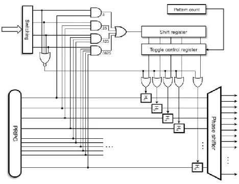
Fig. 1. Basic architecture of a PRESTO generator.
data compression (Section IX) and finally, it wraps up with Section X.
II. BASIC ARCHITECTURE
Fig. 1 shows the basic structure of a PRESTO generator. An n-bit PRPG connected with a phase shifter feeding scan chains forms a kernel of the generator producing the actual pseudorandom test patterns. A linear feedback shift register or a ring generator can implement a PRPG. More importantly, however, n hold latches are placed between the PRPG and the phase shifter. Each hold latch is individually controlled via a corresponding stage of an n-bit toggle control register. As long as its enable input is asserted, the given latch is transparent for data going from the PRPG to the phase shifter, and it is said to be in the toggle mode. When the latch is disabled, it captures and saves, for a number of clock cycles, the corresponding bit of PRPG, thus feeding the phase shifter (and possibly some scan chains) with a constant value. It is now in the hold mode. It is worth noting that each phase shifter output is obtained by XOR-ing outputs of three different
hold latches. Therefore, every scan chain remains in a low-power mode provided only disabled hold latches drive the corresponding phase shifter output [40].
As mentioned previously, the toggle control register super-vises the hold latches. Its content comprises 0s and 1s, where 1s indicate latches in the toggle mode, thus transparent for data arriving from the PRPG. Their fraction determines a scan switching activity. The control register is reloaded once per
pattern with the content of an additional shift register. The enable signals injected into the shift register are produced in a probabilistic fashion by using the original PRPG with a programmable set of weights. The weights are determined by four AND gates producing 1s with the probability of 0.5, 0.25, 0.125, and 0.0625, respectively. The OR gate allows choosing probabilities beyond simple powers of 2. A 4-bit register
Switching is employed to activate AND gates, and allows selecting a user-defined level of switching activity. For example, the switching code 0100 will set to 1, on the average,
25% of the control register stages, and thus 25% of hold latches will be enabled. Given the phase shifter structure, one can assess then the amount of scan chains receiving constant values, and thus the expected toggling ratio.
An additional 4-input NOR gate detects the switching code
0000, which is used to switch the LP functionality off. It is worth noting that when working in the weighted random mode, the switching level selector ensures statistically stable content of the control register in terms of the amount of 1s it carries. As a result, roughly the same fraction of scan chains will stay in the LP mode, though a set of actual low toggling chains will keep changing from one test pattern to another. It will correspond to a certain level of toggling in the scan chains. With only 15 different switching codes, however, the available toggling granularity may render this solution too coarse to be always acceptable. Section III presents additional features that make the PRESTO generator fully operational in a wide range of desired switching rates.
III. FULLY OPERATIONAL GENERATOR
Much higher flexibility in forming low-toggling test patterns can be achieved by deploying a scheme presented in Fig. 2. Essentially, while preserving the operational principles of the basic solution, this approach splits up a shifting period of every test pattern into a sequence of alternating hold and toggle intervals. To move the generator back and forth between these two states, we use a T-type flip-flop that switches whenever there is a 1 on its data input. If it is set to 0, the generator enters the hold period with all latches temporarily disabled regardless of the control register content. This is accomplished by placing AND gates on the control
register outputs to allow freezing ofall phase shifter inputs. This property can be crucial in SoC designs where only a single scan chain crosses a given core, and its abnormal toggling may cause locally unacceptable heat dissipation that can only be reduced due to temporary hold periods. If the T flip-flop is set to 1 (the toggle period), then the latches enabled through the control register can pass test data moving from the PRPG to the scan chains.
Available online:https://edupediapublications.org/journals/index.php/IJR/ P a g e | 1645 example, when in the toggle mode, the input multiplexers
observe the Toggle register. Once the weighted logic outputs 1, the flip-flop toggles, and as a result all hold latches freeze in the last recorded state. They will remain in this state until another 1 occurs on the weighted logic output. The random occurrence of this event is now related to the content of the Hold register, which determines when to terminate the hold mode.
a way that the entire generator will produce pseudorandom test patterns having a desired level of toggling T provided the scan chains are balanced. The procedure of selecting these parameters consists of the following steps.
1) For each switching code k,k= 1, . . ., 15, determine the corresponding probability pk of injecting a 1 into the shift register. These values are as follows: p1= 0.5,
p2 = 0.25, p3=0.625, p4=0.125, p5=0.5625,
p6 = 0.34375, p7= 0.671875, p8= 0.0625, p9 = 0.53125, p10 = 0.296875,p11 = 0.6484375, p12 =
0.1796875, p13= 0.58984375, p14= 0.38476563, and
p15=0.69238281.
2) As can be seen in Fig. 2, the values pk obtained in step 1 determine as well the probability of asserting the T flip- flop input for each hold (toggle) code k, and then the corresponding duration hk (tk) of the hold (toggle) duty cycle. Clearly, hk=tk= 1/pk .
3) Given the size n of PRPG, determine, for each switching code k, the average number nk of 1s occurring in the control register. As can be easily verified, nk=pk×n. 4) For each value of nk (the number of enabled hold latches),
find the average number ak of active scan chains, i.e., scan chains that are not in the LP mode. This number is determined by the phase shifter architecture, and it also depends on the actual locations of 1s in the
control register. Therefore, 1000 n-bit random combina-tions having exactly nk 1s are generated to obtain the number of active scan chains in each case, and finally the number ak of active scan chains is averaged over all 1000 samples. Fig. 5.
T oggling (WTM) for five designs with 32- and 33-bit PRPGs.
standard deviation bounding the average value curve from the top and the bottom. The last (blue) curve represents maximal values (averaged over maximal values obtained for all examined designs) recorded for each toggling rate. As can be seen, the resultant switching activity follows closely, with small values of standard deviation, the requested rates.
Fig. 5 gathers experimental results similar to those of Fig. 4 but obtained in a slightly different way. Before plotting the actual values of toggling rates and the remaining statistics, experiments for every single toggling rate were performed for 32- and 33-bit PRPGs (the 32-bit ring generator uses a primitive polynomial x32+x25+x15+x7+ 1). Note that phase shifters are separately synthesized in each case. The resultant toggling rates were compared, and switching activity with a smaller absolute dispersion from the expected value was chosen as the final result. It appears that in certain cases it is
preferable to pick a 32-bit PRPG rather than a 33-bit one, or
vice versa. This strategy yields virtually a straight line with respect to toggling rates, as shown in Fig. 5, hence offering an accurate mapping between the user-selected values of switching activity and the actual circuit response. One can also observe reduced maximal values and smaller standard deviations in this case.
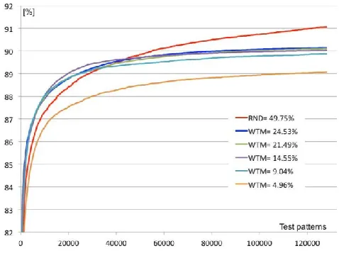
The objective of the second group of experiments was to evaluate tests produced by a 32-bit PRESTO and determine their fault coverage for various requested toggling rates. The results for one of the industrial designs deployed in this paper are shown in Fig. 6. Similar outcomes for a BIST-ready design are shown in Fig. 7. The curves correspond to (requested) toggling rates from 5% to 25% in steps of 5%. In each test case, an additional red curve reports a reference fault cover-age obtained by applying purely pseudorandom test patterns with the effective toggling rates around 50%. One result is clear: performance of the PRESTO generator remains highly predictable. In particular, with the increasing switching activity single stuck-at fault coverage increases as well. In fact, in some designs (Fig. 7) fault coverage of certain LP tests can be higher than that of conventional pseudorandom patterns. Typically, however, one may observe a gap between PRESTO-produced tests and their random counterparts. Fortunately, PRESTO has
Fig. 6. Fault coverage for different toggling rates.
Fig. 7. Fault coverage for a BIST -ready design.
ability to reduce this gap by a proper selection of the control register content as we demonstrate in Section VI.
VI. IMPROVING FAULT COVERAGE GRADIENT
Available online:https://edupediapublications.org/journals/index.php/IJR/ P a g e | 1646 leav-ing a PRPG can also be transformed in a more
deterministic fashion as shown, for example, in [37], [46], and [55]. Along the same lines, we will demonstrate that PRESTO-produced LP test patterns are also capable of visibly improving a fault-coverage-to-pattern-count ratio.
Assuming that the toggle control register can also be driven by deterministic test data (see location of an additional multi-plexer in the front of a shift register in Fig. 8), test patterns can be produced with better-than-average fault coverage. The pro-posed method begins by computing the PRESTO parameters,
s described in Section IV. Subsequently, ATPG is repeatedly invoked until either a desired PRESTO pattern count or a fault coverage limit is reached. The ATPG produces test cubes in one per fault fashion. The number of generated test cubes is limited (in each iteration) for performance reasons. As confirmed by many experiments, the properly selected limit has a negligible impact on test quality. The obtained test cubes are now deployed to arrive with the content of the control register, as described in the following.
Given the PRESTO switching code, our goal is now to find the corresponding distribution of 1s in the control register that maximizes the fault detection probability. The procedure starts by reducing each ATPG-produced test cube to a set of scan chains containing more than one specified bit. This set will be further referred to as a base. For example, let a test cube feature the following specified scan cells: {(s,c): (4, 13), (4, 2), (13, 34), (13, 31), (45, 11)}, wheresis a scanchain, and c is a cell location within the scan chain. The base is thus given by {4, 13}; note that chain 45 is not included as it features only one specified scan cell. A good chance (50%) of producing a given logic value in a purely pseudorandom fashion is a rationale behind excluding from any base scan chains hosting a single specified bit. As a result, more bases can be subsequently combined together to produce a single control setting.
Given the phase shifter architecture, one can determine, for each base, the minimal number of phase shifter inputs—or equivalently the number of 1s in the toggle control register— required to activate the specified scan chains. These inputs are obtained by solving the minimum hitting set problem, where we find, in a greedy fashion, the minimal set of phase shifter inputs that intersects all subsets of phase shifter inputs capable of activating specified scan chains of a given base. Recall that the number of such inputs (and thus the number of 1s in the control register) is further constrained by the preselected switching code. For example, the switching code
0100 sets the limit on the number of 1s in the 32-bit control register to 8. Hence, if a base exceeds the limit, it is excluded from subsequent steps of the procedure. Finally, each base is assigned weight w, which is simply the number of specified bits in the corresponding test cube. It is worth noting that a reciprocal of w can be regarded as the likelihood of yielding the test pattern by a generator of purely pseudorandom vectors.
Let C be an initially empty set of bases. Once all weights are determined, we add to C a minimum-weight base. Next,
every remaining base B is assigned a cost value, which is equal to the smallest number of 1s in the control register that would be required to activate all scan chains in {C∪B}.
A minimum-cost base (or a minimum-weight base if there are two or more bases with the same minimal cost) is then added to C , and costs associated with the remaining bases are recomputed accordingly. The procedure continues until either the limit of 1s in the control register is reached or all bases are already in C . The control register content that activates all scan chains from C is then provided to PRESTO.
For each control register setting, PRESTO is run to pro-duce a certain number of pseudorandom test patterns. These patterns are subsequently fault-simulated, and detected faults are dropped from the list. Experimental results demonstrating feasibility of this method can be found in Section IX.
VII. LP DECOMPRESSOR
In order to facilitate test data decompression while preserv-ing its original functionality, the circuitry of Fig. 2 has to be rearchitected. This is shown in Fig. 8. The core principle of the decompressor is to disable both weighted logic blocks (V
and H ) and to deploy deterministic control data instead. In particular, the content of the toggle control register can now be selected in a deterministic manner due to a multiplexer placed in front of the shift register. Furthermore, the Toggle and Hold registers are employed to alternately preset a 4-bit binary down counter, and thus to determine durations of the hold and toggle phases. When this circuit reaches the value of zero, it causes a dedicated signal to go high in order to toggle the T flip-flop. The same signal allows the counter to have the input data kept in the Toggle or Hold register entered as the next state.
Both the down counter and the T flip-flop need to be initialized every test pattern. The initial value of the T flip-flop decides whether the decompressor will begin to operate either in the toggle or in the hold mode, while the initial value of the counter, further referred to as an offset, determines that mode’s duration. As can be seen, functionality of the T flip-flops remains the same as that of the LP PRPG (see Section III) but two cases. First of all, the encoding procedure (Section VIII) may completely disable the hold phase (when all hold latches are blocked) by loading the Hold register with an appropriate code, for example, 0000. If detected (No Hold signal in the figure), it overrides the output of the T flip-flop by using an additional OR gate, as shown in Fig. 8. As a result,
Available online:https://edupediapublications.org/journals/index.php/IJR/ P a g e | 1647
g. 9. T ransitions (arrows) in a test cube.
produced at the end of the ring generator initialization phase reloads all latches with the current content of this part of the decompressor.
Finally, external ATE channels (feeding the original PRPG) allow one to implement a continuous flow test data decompres -sion paradigm such as the dynamic LFSR reseeding. Given the size of PRPG, the number of scan chains and the correspond-ing phase shifter, the switching code, the offset, as well as the values kept in the Toggle and Hold registers, the entire decompressor will produce deterministic (decompressed) test patterns having a desired level of toggling provided the scan chains are balanced. The corresponding encoding procedure, including an appropriate selection of the aforementioned para-meters, consists of steps described in Section VIII.
VIII. ENCODING ALGORITHM
The decompressor architecture presented in Section VII is tightly coupled with a compression procedure. It partitions a given test pattern into several blocks corresponding alternately to hold and toggle periods. Recall that in the hold mode, all phase shifter inputs are frozen due to disabled hold latches, whereas the toggle mode allows certain inputs of the phase shifter to receive data from the ring generator provided the corresponding bits of the toggle control register are asserted. Since this register is updated once per pattern, scan chains driven only by disabled hold latches are loaded with constant values, and thus remain in the LP mode for the entire pattern. The remaining chains receive either constant values (the HCs) or results of XOR-ing certain outputs of PRPG (during the
TCs) among which at least one is enabled.
The actual toggle rate (TR) percentage, measured as a weighted transition metric, is given by
TR = 50(n/S)(T/(T+H)) (5)
where n is the number of scan chains driven by at least one enabled phase shifter input, S is the total number of scan chains, and T and H correspond to the durations of toggle and hold periods, respectively. It is also assumed that switching at the level of 50% corresponds to an LP mode turned off. The values of T and H , the offset cycles, as well as the content of the toggle control register form LP templates (LPTs). They are determined prior to further encoding steps based on the analysis of test cubes forming a cube pool. As a result, they allow merging and encoding successive test cubes in an incremental fashion, with no repetitions in a flow, as explained in the following.
First, c test cubes from the cube pool are used to initialize c
LPT. We begin by mapping the test cubes into lists of transitions. Each transition is determined by two successive specified bits of the opposite logic values located in the same
Fig. 10. Steps to determine H,T , and O .
scan chain. In addition to its flanking bits x and y, each transition is characterized by a span, i.e., the number of clock cycles separating x from y. It is worth noting that some specified bits contribute to two transitions, whereas other bits are not involved in forming any transitions, as shown in Fig. 9.
Having instantiated a given empty template, the correspond-ing list of transitions is used to arrive with the initial durations of the toggle (T ), hold (H ), and offset (O ) periods. These values are chosen conservatively such that the ratio T/H is minimal, and there are no transitions within a single hold period. The former condition ensures that the template can still accommodate some of newly produced test cubes. The latter condition can be rephrased as follows: for each transition either its span is greater than H or at least one of its flanking bits lies within a toggle period. The actual algorithm to yield the desired values of T,H , and O can be summarized as follows (Fig. 10).
1) Given a test cube and its transitions, find the earliest transition ending point e (a black triangle in the figure) and assign a single bit toggle phase (T= 1) to cycle e. 2) Mark all transitions crossing e, as they will not end up
within a single hold period.
3) Increase the toggle period by extending it up to the next unmarked transition starting point. Repeat this step as long as the duration of the toggle period does not exceed a certain threshold (in this paper, ten cycles).
4) Find the next unmarked transition ending point e —it determines a duration H of the hold period unless H is larger than a certain threshold. In the former case go to step 6, otherwise invoke step 5.
5) Find the value of H that minimizes the ratio T/H and, by adding new hold and toggle phases, keeps the cycle e
within a toggle period.
6) Set the offset period O to e mod (T+H)−H , if we begin with an incomplete toggle period, and O=e mod (T+H), otherwise.
Available online:https://edupediapublications.org/journals/index.php/IJR/ P a g e | 1648
.
a newly added red transition that must not stay within the hold period). Ensure that the sum T+H remains unchanged. The ratio T/H , on the other hand, may vary, thus its minimizing can guide this step toward an optimal solution. Note that, for example, enlarging the toggle period reduces the length of the hold period and it may also impact the number of offset cycles.
Once the above procedure completes, one has to make sure that all scan chains hosting transitions are enabled. This can be achieved as long as there is at least one enabled phase shifter input that feeds a given scan through an XOR gate within the phase shifter. Finding the minimal subset of the control register stages needed to activate the required scan chains is equivalent to solving the minimum hitting set problem. Furthermore, the switching activity associated with the template is checked by using formula (5) and compared against the desired toggling ratio
τ . If the resultant toggling is below τ , then the test cube can be finally accepted as a part of the template. Otherwise, the test cube is not compressible given power constraints and is discarded. The template returns to its initial status.
When all templates have been initialized, we attempt to link them with the remaining (new) test cubes. If a template cannot accommodate certain transitions featured by a newly picked test cube, then the durations of toggle, hold, and offset periods can be further adjusted in a similar fashion to that of step 7 of the algorithm presented above. If the cube fits to the template, and new active scan chains are known, then we recalculate both the content of the toggle control register and the toggling rate. Again, if the toggling is above τ , then the template returns to its previous form, while the test cube is passed to the next template. In addition, if none of the existing templates can accommodate the cube, it remains in the pool until another set of templates is generated such that this particular cube can be eventually assigned to its designated LPT.
The compression of test cubes treats the external test data as Boolean variables used to create linear expressions filling conceptually all scan cells. However, an equation assigned to a given scan cell depends not only on what is yielded by the ring generator, but also on whether a given phase shifter input is enabled or not. If a scan chain is disabled, then a single expression, produced during the first shift-in cycle, represents all of its cells. On the other hand, if a cell belongs to an active scan chain, then its equation is formed by XOR-ing: 1) the
corresponding outputs of the ring generator if they are enabled through the hold latches; and 2) expressions produced during the first shift-in cycle on the disabled ring generator outputs. This expression will be used provided a scan cell is in the toggle mode. If it enters the hold mode, then its equation is going to be the same as that of the preceding and nearest cell which is in the toggle mode and belongs to the same chain. Since we only use 3-input XOR gates to create a phase shifter,
there are seven different scenarios with at least one XOR tap
enabled. Consequently, prior to any compression actions and
to save CPU time, we prepare all possible equations for each scan cell, and subsequently select an appropriate expression when working with a particular LPT.
Having prepared all necessary equations, one can proceed with the test cube encoding. This is carried out in a
mannerT ABLE I
CIRCUIT CHARACTERISTICS—128K RANDOM PATTERNS
similar to that of the conventional EDT flow. It is worth noting, however, that participation of a given test cube in a template does not guarantee its actual merging and compression because of either conflicts on certain specified bits with other test cubes or limited encoding capabilities. Another notable difference between the presented approach and the traditional EDT scheme is the way compression aborts are reported. Typically, a test cube is regarded uncompressible if it cannot be encoded when merged as the first component of a test pattern. Here, the test cube is first employed, with other cubes, to form a template, which in turn modifies equations. Hence, an abort is reported only if the cube is used to make up a LPT, is then chosen as the first component of a test pattern, and its encoding fails. All compressed test cubes are removed from the cube pool, which is subsequently refilled. The algorithm continues by creating a new set of templates as long as the pool is not empty.
IX. EXPERIMENTAL RESULTS
Available online:https://edupediapublications.org/journals/index.php/IJR/ P a g e | 1649 The primary objective of the experiments was to measure
test coverage as a function of several parameters, including: 1) the number of test patterns;
2) the switching activity code; 3) the duration of Toggle (T ) period; 4) the duration of Hold (H ) period.
The actual results are presented in Tables II and III for the industrial designs of Table I. In all experiments reported here,
T ABLE II
FAULT COVERAGE—128K LOW TOGGLING TEST PATTERNS
T ABLE III
LOW TOGGLING TEST PATTERN COUNT VERSUS RANDOM VECTORS
we have used the PRESTO generator with a 32-bit ring genera-tor producing 128K pseudorandom test patterns in a LP mode. Table II is vertically partitioned into columns corresponding to five different (target) toggling rates. Switching activity codes as well as parameters H and T were selected automatically, as shown in Section IV. The columns of Table II list the fault coverage for successive test cases. As can be seen, the resultant fault coverage remains close to the reference coverage reported in Table I, while the switching activity is reduced to the desired levels of toggling. Note that some results indicate higher fault
coverage if the scan chains receive the low toggling patterns rather than conventional pseudorandom vectors. Even if this is a circuit-specific feature, it nevertheless appears to be the case across several designs.
The objective of the analysis summarized in Table III was to determine the impact of our LP test generator performance on a pattern count. Alternatively, we would like to as sess how long it takes to match fault coverage of purely pseudorandom test patterns (shown in the middle column of Table I) with vectors produced by the PRESTO generator. Let L(p) and R( p)denote fault coverage obtained by applying p lowtoggling and
purely random test patterns, respectively. Clearly, there are two possible scenarios: either L(p) <R(p) or L ( p) > R( p). In the first case, we can assess a pseudorandomtest length q
to get fault coverage L(p), where q<p. The other case is symmetrical; we need to find the number of LP test patterns
r that suffice to match fault coverage R(p), where r<p. The entries of Table III, corresponding directly to those of Table II, are ratios v that (depending on one of the above scenarios) are either equal to p/q or r/p. Clearly, v< 1 indicates cases where an LP test is shorter than its random counterpart. If v> 1, then the presented values are indicative of how many additional LP test patterns must be applied to obtain R(p). In Table III, two horizontal segments present results for two values of p: 16K and 128K. As an example, the entry 2.78 for design D5, 16K vectors, and WTM = 20% indicates that the resultant fault coverage due to 16K low toggling test patterns can be reached almost three times faster by using pseudorandom tests. On the other hand, the entry 0.57 for design D3, 128K vectors, and WTM = 20% indicates that LP tests can offer the same fault coverage as that of 128K random patterns in approximately half shorter test time. One may also observe that for some test cases the ratio v is quite large. It occurs either for aggressively low toggling rates or in some designs where certain groups of faults are much more difficult to detect by means of test patterns with relatively low diversity of binary sequences.
The objective of the second group of experiments is to assess effectiveness of the scheme described in Section VI, i.e., to measure a degree of test time reduction that one can achieve when using a precomputed deterministic content of the control register as compared with application of pseudorandom patterns with otherwise similar power constraints. We present experimental results for industrial designs D1–D6 whose char-acteristics are given in Table I.
Available online:https://edupediapublications.org/journals/index.php/IJR/ P a g e | 1650 control register settings per iteration (Section VI). In
addition, in order to minimize the average number of specified bits occurring in test cubes, ATPG used a SCOAP-based decision order.
The experimental results for 10% toggle rate repre-sented by the WTM are shown in Fig. 11. The presented curves correspond to the designs of Table I as follows. For BIST-ready designs D1 and D2, we depict their individual curves, while (in addition to their individual curves) a bold red line is averaging results over test cases D3, D4, D5, and D6. Given a number t of LP pseudorandom PRESTO-generated test patterns (and hence the corresponding fault coverage C
not shown in the figure), a single entry in these plots demonstrates a difference (or equivalently a gain) t –g, where g is the number of test patterns applied by a determin-istically controlled PRESTO to arrive at the fault coverage
C . For example, consider circuit D2 and its gain curve. As can be seen, we need roughly 70K fewer vectors to reach the same fault coverage as that of 100K PRESTO-produced pseudoran-dom test patterns with the same switching activity. Clearly,
test application time is reduced in this case by more than half. In the large majority of test cases, the deterministic control data allowed us to reduce the number of test patterns, and thus test application time, in a similar fashion. In particular, BIST-ready designs with a moderate number of scan chains witness considerably steep gain curves. We have also noticed little improvement in test time reduction for a few non-BIST-ready circuits. It appears that these designs have featured a large number of scan chains driven by a relatively small phase shifter. Increasing the number of phase shifter inputs typically alleviates the situation.
Fig. 12 plots fault coverage results obtained for two BIST-ready designs D1 and D2 while choosing different toggling rates and sweeping the number of applied test pat-terns. As can be seen, in all examined cases fault coverage of test patterns generated by a deterministically controlled PRESTO (solid lines) is visibly improved over the base-line results (dashed lines) obtained for PRESTO-produced pseudorandom patterns with a similar switching activity. The improvement in fault coverage occurs systematically across all toggling rates, and the deterministically controlled PRESTO outperforms its conventional counterpart for virtually all exam-ined test durations.
Eventually, we experimentally assess performance of the compression scheme of Sections VII and VIII. Experiments are run on industrial designs whose characteristics are given in Table IV. Table V presents results of experiments con-ducted with 64-bit decompressors and the desired scan shift-in switching level set to 5%, 10%, and 15%. Again, the average WTM estimates the resultant switching activity for scan shift operations, while the average WSA measures toggling in the capture mode by observing the switching activity at each gate in the circuit. All experiments are conducted in such a way that the original EDT-based test coverage is always preserved. As can be seen, in all examined test cases the resultant scan shift-in switching activity (WTM load) remains very close to the requested one. We have also observed a similar trend for
other switching rates, for which results are not reported in Table V. It is worth noting that reducing the load switching has a positive impact on the switching activity during capture and unloading of scan chains.
REFERENCES
[1] A. S. Abu-Issa and S. F. Quigley, “Bit-swapping LFSR for low-power BIST ,” Electron. Lett., vol. 44, no. 6, pp. 401–402, Mar. 2008. [2] C. Barnhart et al., “Extending OPMISR beyond 10x scan test
efficiency,” IEEE Design Test, vol. 19, no. 5, pp. 65–73, Sep./Oct. 2002.
[3] S. Bhunia, H. Mahmoodi, D. Ghosh, S. Mukhopadhyay, and K. Roy, “Low-power scan design using first-level supply gating,” IEEE Trans.Very Large Scale Integr. (VLSI) Syst., vol. 13, no. 3, pp. 384– 395,Mar. 2005.
[4] M. Chatterjee and D. K. Pradham, “A novel pattern generator for near-perfect fault-coverage,” in Proc. 13th IEEE Very Large Scale Integr.(VTSI) Test Symp., Apr./May 1995, pp. 417–425. [5] F. Corno, M. Rebaudengo, M. S. Reorda, G. Squillero, and M. Violante,
“Low power BIST via non-linear hybrid cellular automata,” in
Proc.18th IEEE Very Large Scale Integr. (VTSI) Test Symp., May 2000,
pp.29–34.
[6] D. Das and N. A. T ouba, “Reducing test data volume using exter-nal/LBIST hybrid test patterns,” in Proc. Int. Test Conf. (ITC), 2000, pp.115–122.