University of New Orleans University of New Orleans
ScholarWorks@UNO
ScholarWorks@UNO
University of New Orleans Theses and
Dissertations Dissertations and Theses
Summer 8-4-2011
Enhancing the Verification-Driven Learning Model for Data
Enhancing the Verification-Driven Learning Model for Data
Structures with Visualization
Structures with Visualization
Yashwanth Reddy Kondeti
University of New Orleans, [email protected]
Follow this and additional works at: https://scholarworks.uno.edu/td
Part of the Computer Sciences Commons
Recommended Citation Recommended Citation
Kondeti, Yashwanth Reddy, "Enhancing the Verification-Driven Learning Model for Data Structures with Visualization" (2011). University of New Orleans Theses and Dissertations. 461.
https://scholarworks.uno.edu/td/461
This Thesis-Restricted is protected by copyright and/or related rights. It has been brought to you by
ScholarWorks@UNO with permission from the rights-holder(s). You are free to use this Thesis-Restricted in any way that is permitted by the copyright and related rights legislation that applies to your use. For other uses you need to obtain permission from the rights-holder(s) directly, unless additional rights are indicated by a Creative Commons license in the record and/or on the work itself.
Enhancing the Verification-Driven Learning Model for Data Structures with Visualization
A Thesis
Submitted to the Graduate Faculty of the University of New Orleans in partial fulfillment of the requirements for the degree of
Master of Science In
Computer Science
by
Yashwanth Reddy Kondeti B.E., SRM University, India, 2008
ii
ACKNOWLEDGEMENT
Sincere thanks to my parents and all my friends who gave me so much love and encouragement.
I would like to thank Dr. Shengru Tu for his excellent guidance and valuable feedback without
which this thesis would not have been possible. I would also like to extend thanks to Dr.
iii
Table of Contents
List of Figures ...v
List of Tables ... viii
Abstract ... ix
1. Introduction ...1
2. Background ...4
2.1 Data Structures ...4
2.2 Adobe Flex ...4
2.3 MXML ...5
2.4 Action Script ...5
2.5 Adobe Flash Builder ...5
2.6 Adobe Flash Player ...6
2.7 Flash Professional CS5 ...6
3. Teaching Data Structures with Operational Animations and Code Visualization ...7
3.1 Lab Design ...7
3.1.1 Animation and Code Visualization for Array ...7
3.1.2 Animation and Code Visualization for Linked List ...9
3.1.3 Animation and Code Visualization for Doubly-Linked List ...12
3.1.4 Animation and Code Visualization for Circular-Linked List ...13
3.1.5 Animation and Code Visualization for Stack ...15
3.1.6 Animation and Code Visualization for Binary Tree Traversal ...17
3.1.7 Animation and Code Visualization for Hash Table ...18
3.1.8 Animation and Code Visualization for AVL Tree ...19
3.2 Visualizing Program Execution by Highlighting Code ...24
4. Application of Animations in Learning Tool ...26
iv
4.2 Code Highlighting for Bug Identification ...66
5. Learning Tool Implementation ...69
6. Discussion and Conclusion ...73
References ...74
v
List of Figures
Figure1 ...8
Figure2 ...9
Figure3 ...10
Figure4 ...11
Figure5 ...12
Figure6 ...13
Figure7 ...14
Figure8 ...15
Figure9 ...16
vii
Figure53 ...53
Figure54 ...54
Figure55 ...55
Figure56 ...55
Figure57 ...56
Figure58 ...57
Figure59 ...58
Figure60 ...59
Figure61 ...60
Figure62 ...60
Figure63 ...61
Figure64 ...61
Figure65 ...62
Figure66 ...64
Figure67 ...65
Figure68 ...66
Figure69 ...67
Figure70 ...67
Figure71 ...70
Figure72 ...71
viii
List of Tables
Table 1 ...27
ix
Abstract
The thesis aims at teaching various data structures algorithms using the Visualization Learning
tool. The main objective of the work is to provide a learning opportunity for novice computer
science students to gain a broader exposure towards data structure programming. The
visualization learning tool is based on the Verification-Driven Learning model developed for
software engineering. The tool serves as a platform for demonstrating visualizations of various
data structures algorithms. All the visualizations are designed to emphasize the important
operational features of various data structures. The learning tool encourages students into
learning data structures by designing Learning Cases. The Learning Cases have been carefully
designed to systematically implant bugs in a properly functioning visualization. Students are
assigned the task of analyzing the code and also identify the bugs through quizzing. This
provides students with a challenging hands-on learning experience that complements students’
textbook knowledge. It also serves as a significant foundation for pursuing future courses in data
structures.
Keywords: Data Structures, Visualization Learning tool, Verification-Driven Learning Model,
1
1. Introduction
Learning programming concepts is often considered very challenging for novice students [1].
High attrition rate among students in data structures courses is a common phenomenon in
computer science programs. The challenge is largely because students often fail to understand all
the aspects of the algorithms and intricate code that implements them. In learning of data
structures, it is imperative that students understand the abstract models and the algorithms in an
intuitive and tangible manner at their initial learning stage.
The target group of people for this thesis is the computer science students enrolled in the
data structures courses. Our selection of this target group is based on the fact that learning data
structures is important as they take a pivotal position in programming. Textbooks are an
important source to students that explains the working functionality of programming concepts
such as data structures. However, recent studies have found that the usefulness of a textbook in
exposing the entirety of a concept matter is very limited [2]. Students are often not able to
identify the important features in programming for data structures. To prevent this, students need
additional help in learning data structures.
Hands-on activities are regarded as an efficient means in helping students comprehend
the programming concepts. Studies show that students who are encouraged to attend lab courses
along with the classroom lectures have performed well in a definitive testing environment [3].
These lab courses use animations and other visual representations that bring the abstract concepts
of the object oriented programming to the fore [3].
Our project is based on teaching data structures with the help of code visualization and
operational animations. Failures in understanding the object-oriented programming occurs
2
the program code [4]. We believe that learning data structures poses similar challenges. To
develop an efficient learning platform, it is necessary that these two issues are addressed.
Students are given proper user interfaces to interact with the programs, and focus on the
important aspects of the data structures that would otherwise be overlooked in just reading. To
address the aforementioned issues, we have implemented learning cases based on the
verification-based learning model for the students.
The project has enhanced the Verification-Driven learning model (VDL) with
high-quality animations and code visualizations. The basic VDL learning procedure [5] has been
adjusted to the process given below:
Step 1: Students begin the process by reviewing the functionalities of the data structures and
understanding the goal of the operations.
Step 2: Students interact with the program by playing the animations of operations provided.
These operations are based on a set of data structures.
Step 3: Students go through the task of analyzing the code and understand the code in an
implementation point of view. They will be able to relate the code implementation to the
actions of the animations.
Step 4: Students are challenged by multiple-choice questions that require the students to identify
the bugs that are deliberately planted in the program.
Step 5: Students will make use of the code logic visualization provided along with the animations
3
With a successful implementation of the aforementioned process of steps, students will
be able to identify the extent to which they understand the concepts implemented in the learning
model. A VDL model for data structures supported by visualization consists of the following
aspects. This list is a customization of the VDL model for general software engineering [5].
1. A working implementation of the set of subject data structures.
2. An explanation of the algorithms of the subject data structures.
3. Animations that visualize the specifications of data structures and their functionalities.
4. An interactive user interface that controls the animations.
5. Test cases that encourage the students to do critical thinking and analyze the algorithms
implemented by the code
4
2. Background
A brief description of the concepts, tools and development environments utilized in the project
are given in this chapter.
2.1 Data structures
A data structure is a particular way of organizing data in a memory so that it can be used
efficiently. Data structures are the foundation in programming and very often used as organized
means of storing data in software design. Only a few data structures are involved in disk storage.
For example, B-Trees are usually used for the implementing databases.
Array, Linked List, Stack, Hash Map, Heap, Queue, Tree, etc., are the most common
used data structures in programming. In a broader sense, data structures are categorized under
two types: Linear and Non Linear data structures. For the purposes of demonstration of
animation and learning cases, we have implemented the animations for the following data
structures: Array, Linked List, Doubly-Linked List, Circular-Linked List, Stack, Queue, Binary
Tree, AVL Tree and Hash Table.
2.2 Adobe Flex
The Flex SDK in the visualization learning tool is used to provide a launching platform for both
flex and flash enabled animations. The entire application layout and design is carried out through
Flex.
Adobe Flex is a free, open source framework for building highly interactive, expressive
web applications that deploy consistently on all major browsers, desktops, and operating
systems. Flex includes a rich component library for creating rich Internet applications (RIAs).
Flex applications considerably reduce the network burden and also provide fast rendering ability
5
it easy for the flex applications to render the web content. Typical HTML applications consist of
multiple pages and as a user navigates between them, the application data must be passed along
so the application itself (the collection of pages and functionality it consists of) can maintain
state.
In contrast, Flex applications are stateful. A Flex application is embedded in a single
HTML page that the user does not leave and is rendered by Flash Player. The Flex application
can dynamically change views and send and retrieve data asynchronously to the server in the
background, updating but never leaving the single application interface.
2.3 MXML
MXML is a convenience language which provides an alternate way to generate ActionScript
using a declarative tag-based XML syntax. When an application is compiled, the MXML is
parsed and converted to ActionScript in memory and then the ActionScript is compiled into byte
code with swf file format.
2.4 Actionscript
Actionscript is used to write the design and layout implementation logic in Flex. Also, it is used
to manipulate the timing aspects of the animation in the Flash Professional CS5. ActionScript
code is compiled to swf file format which is then loaded in to the browser of the client and
played using Adobe Flash Player.
2.5 Adobe Flash Builder
Flash Builder 4.0 is used to create the flex background for the learning tool. The use of Flash
Builder for the flex applications makes it very convenient to manage, deploy and debug the flex
6
2.6 Adobe Flash Player
Adobe Flash Player is a browser plugin that is required to deploy the Flex/Flash swf files on the
client side. It is an Active X control that has a much richer object model and rendering engine
that allows developers to include more highly expressive and interactive content in web
applications.
2.7 Flash Professional CS5
Adobe Flash Professional CS5 is used to design the animations necessary for the concept
visualization of the data structure functionalities. The compiled swf files are deployed into the
7
3. Teaching Data structures with Operational Animations and Code Visualization
The primary objective of the animations is to illustrate the algorithms of data structures in a
visually appealing and intuitive manner. The final goal is to provide students with a sound
knowledge through concrete examples.
3.1 Lab Design
The project implements various animations to illustrate the working processes of the data
structure algorithms. To help the users understand the algorithms in an efficient way, the
animations are illustrated along with the visualization of the code. Additionally, the play/pause
and replay buttons allow students to control the animations while they are being visualized. The
following are the brief descriptions of the data structures and their algorithm animations we have
developed for the project.
3.1.1 Animation and Code Visualization for Array
An array is a data structure consisting of a group of elements occupying a contiguous area of
memory. The applications of arrays are often mathematical vectors and matrices.
Our project implements animations for a number of algorithms including sorting,
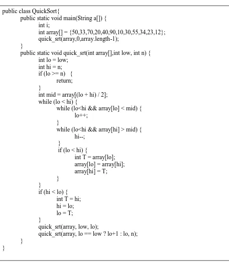
searching, insertion and deletion in arrays. We have implemented animations of quick sort,
bubble sort, insertion sort and merge sort. Figure 1 shows the code that implements the quick
8
Figure 1
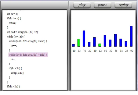
Figure 2 shows the snapshot of the quick sort animation. Each bar in the animation
represents an individual element of the array. The bars highlighted in green indicate the items
currently being compared for sorting. By showing the movement of the elements in the array, we public class QuickSort{
public static void main(String a[]) { int i;
int array[] = {50,33,70,20,40,90,10,30,55,34,23,12}; quick_srt(array,0,array.length-1);
}
public static void quick_srt(int array[],int low, int n) { int lo = low;
int hi = n; if (lo >= n) {
return; }
int mid = array[(lo + hi) / 2]; while (lo < hi) {
while (lo<hi && array[lo] < mid) { lo++;
}
while (lo<hi && array[hi] > mid) { hi--;
}
if (lo < hi) {
int T = array[lo]; array[lo] = array[hi]; array[hi] = T;
} }
if (hi < lo) { int T = hi; hi = lo; lo = T; }
quick_srt(array, low, lo);
quick_srt(array, lo == low ? lo+1 : lo, n); }
9
visualize the actions of the algorithm. Each line of the code in the code visualization box is
highlighted when the corresponding action happens in the animation.
Fig 2
3.1.2 Animation and code visualization for Linked List
A linked list is a data structure that consists of a sequence of nodes each of which contains a
reference to the next node in the sequence. A linked list data structure can be used to implement
several other data structures such as stacks and queues. One major advantage of linked list is that
the list elements can be easily added or removed without reallocation or reorganization of the
entire structure.
A linked list contains nodes, each with a reference (a pointer) to its next node. The
10
list are search, insert and delete. In an insert operation, after the new node is added, it is
important to rearrange the references between the nodes.
Pukjhkjhkblic void destNode (int id)
Figure 3
class Node {
public int iData; public Node next; public Node (int id); {
iData = id; }
}
public Node searchNode (int id) { Node destNode = null; if (first !=null) {
Node curNode = first; while (curNode !=null) {
if (curNode.iData == id) { destNode = curNode; break;
}
curNode = curNode.next; }
}
return destNode; }
public void deleteNode (int id) {
Node destNode = searchNode (id); if (destNode !=null) {
if (destNode == first) { first =first.next; }
else {
Node prevNode = searchNode (destNode); prevNode.next = destNode.next;
} }
11
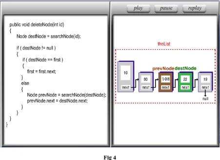
When a node is deleted, the references between the remaining nodes must be rearranged.
Figure 3 shows the code that implements the delete operation in the linked list. Figure 4 shows a
snapshot of the animation of the delete operation in a linked list.
Fig 4
The objective of the animation in Fig 4 is to illustrate the deletion of node 22. The
deletion of the node is accomplished by the change in the references to the nodes that are on
either side of the deleted node. From the figure, the “next” reference of the node 108 is to be
12
3.1.3 Animation and code visualization for Doubly-Linked List
In a doubly-linked list, each node has two references: one reference points to its previous node
and the other points to its next node. Though adding or deleting nodes in a doubly linked list
requires more operations, there is neither need to keep track of the previous node during traversal
nor no need to traverse the list to find the previous node. This makes node reference
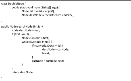
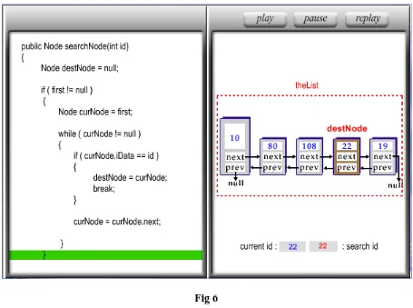
modifications easier. Fig 5 shows the code that implements the search operation in a
Doubly-linked list. Figure 6 is a snapshot of the animation to search node 22.
Figure 5
class DoublyNode {
public static void main (String[] args) { NodeList theList = args[0];
Node destNode = theListsearchNode(22); }
}
public Node searchNode (int id) { Node destNode = null; if (first !=null) {
Node curNode = first; while (curNode !=null) {
if (curNode.iData == id) { destNode = curNode; break;
}
curNode = curNode.next; }
}
13
Fig 6
3.1.4 Animation and code visualization for Circular-Linked List
A circular-linked list is a linked list in which the “next” reference of the last node points to the
first node. Hence, a pointer to the last node gives easy access also to the first node, by following
one reference. Thus, in applications that require access to both ends of the list (e.g., in the
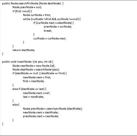
implementation of a queue), a circular structure provides convenience. Figure 8 is a snapshot of
the insert operation of node 20 in a circular-linked list. The animation also shows the
rearrangement of the references of nodes 108 and 22 after inserting node 20. Figure 7 shows the
14
Fig 7
public Node searchPrvNode (Node destNode) { Node prevNode = null;
if (first !=null) {
Node curNode = first;
while (curNode !=first && curNode !==null) { if (curNode.next ==destNode) {
prevNode = curNode; break;
}
curNode = curNode.next; }
}
return destNode; }
public void insertNode (int pos, int id) { Node newNode = new Node (id); Node destNode = searchNode (pos); if (destNode == null ||destNode == first) {
newNode.next = first; first = newNode; }
else if (destNode == last) { newNode.next =null; last = newNode; }
else {
Node prevNode = searchprvNode (destNode); newNode.next = destNode;
prevNode.next = newNode; }
15
Fig 8
3.1.5 Animation and code visualization for Stack
Stack is a data structure that stores its data values in a FILO manner. Each data entry is stacked
on the top of the previous entry. A Stack data structure usually implements two functionalities:
PUSH and POP. Figure 10 is a snapshot of the animation of the application of a stack theStack.
Class stackPop {
public static void main (String [] args) { Stack theStack = new Stack(); theStack.push(20);
theStack.push(30); theStack.push(40);
while (!theStack.isEmpty ()) {
double value = theStack.pop (); System.out.println (value); System.out.println (“,”); }
16
(figure continued)
Fig 9
Figure 9 shows the code that performs the applications of the stack. The animation in
Figure 10 shows that since the value 20 is added first in to the stack, it will be the last item to be
popped out. With each pop operation, exactly one item (on top of the stack) is removed. class Stack {
private int maxSize;
private double [] stackArray; private int top;
private int front; public Stack (int s) {
maxSize = s;
stackArray = new double [maxSize]; top = -1;
front = 0; }
public void push (double j) { stackArray [++top] = j; }
public double pop () {
return stackArray [top--]; }
17
Fig 10
3.1.6 Animation and code visualization for Binary Tree Traversal
Traversal of a tree structure means visiting all the nodes of a tree exactly once. For the purpose
of illustration, inorder, preorder and postorder tree traversals have been implemented. The
following is a snapshot of the inorder traversal of the binary tree.
In an Inorder traversal, the left child, root node and the right child are traversed in the
18
Fig 11
3.1.7 Animation and code visualization for Hash Table
A Hash Table uses a key-value pair to store information in a table. The hash function operates on
the key and the result of the hash function determines the location where the data value has to be
stored. To deal with hash collisions, we applied the linear probing technique to store the data
records. If the intended location to store a key is unavailable, the immediate next slot is
attempted until an empty slot is found to store the data. Figure 12 is a screenshot of the insert
19
Fig 12
As shown in figure 12, the key-value pair entered by the user is stored in the location
determined by the hashing function. The hashing function is:
Hash (key) = key mod 31
The numeric equivalent value of the text key is determined by the customized ASCII
conversion. The numeric value is operated upon by the hashing function to determine the
location where the data needs to be stored. The maximum number of characters for the key is
constrained to 24.
3.1.8 Animation and code visualization for AVL tree
An AVL tree is a nearly balanced binary search tree. The maximum difference between the
heights of the left and right sub trees of any node cannot be greater than 1. Imbalance in the
20
double rotation that adjusts the imbalanced tree. To illustrate the double rotation in the AVL tree,
we insert node 70 into the tree. Figure 13 shows the Avl tree before adding node 70.
Fig 13
When we add node 70 as the right child to node 65, the tree becomes imbalanced at node
90. This is because the height of the left sub-tree of node 90 is now increased to 4 while the
21
Fig 14
To balance the tree, we need to perform double rotation. In the animation, Double
rotation is achieved by two single rotations. First, we perform single rotation at node 50 by
rotating it to the left. Figure 15 shows a snapshot of the animation after rotating the tree at node
22
Fig 15
Since the tree is still not balanced, we perform single rotation at node 90 by rotating it to
the right. Figure 15 shows a snapshot of the animation after the tree is rotated at node 90. From
the Figure 16, it can be seen that the tree is now balanced with the highlighted sub-tree shifting
to the right side of the root node. The code to perform the tree rotation in the tree is given in
23
Fig 16
(figure continued) //x – the new node to insert
// t – the node that roots the tree
private AvlNode insert (Comparable x, Avl Node t) { if (t == null)
t = new AvlNode (x, null, null); else if (x.compareTo (t.element) <0) {
t.left = insert (x, t.left);
if ( height (t.left ) – height (t.right) == 2) if (x.compareTo (t.left.element) < 0 ) t = rotateWithLeftChild (t);
else
24
Fig 9
Fig 17
3.2 Visualizing Program Execution by Highlighting Code
Dynamically highlighting the currently executing code has been a common feature of most
program debugging tools. To demonstrate the actions of the code, we have implemented the
feature of dynamic code highlighting along with animations. When each action happens in the
animation, the corresponding line of code is highlighted. Students can replay and pause to trace
the relationship between the actions and code to the most detailed level.
The snapshot in Figure 18 illustrates the code highlighting feature in the Push algorithm
of a stack. Students can use the pause and replay buttons to understand the animation and
analyze the current line of code that the animation is implementing. The figure shows the push
operation on the stack by adding the new value 40, along with the corresponding code line being
highlighted in the code visualization box. else if (x.compareTo (t.element) >0) {
t.right= insert (x, t.right);
if ( height (t.right ) – height (t.left) == 2) if (x.compareTo (t.right.element) < 0 ) t = rotateWithRightChild (t);
else
t = doubleWithRightChild (t); }
else ;
t.height = max ( height (t.left ), height (t.right)) +1; return t;
25
Fig 18
By helping students simultaneously co-relate the code with the actions in the animation,
we hope to provide them a good visualization tool for learning actual implementation.
The learning tool has two modes: The Learning Mode and the Quiz mode. The Learning
mode employs all the functionally correct animation visualizations. The debug mode employs
the animations that are deliberately tweaked to implant errors in the animations. Students are
assigned the task of identifying the problems in these animations and are asked to answer the
multiple choice questions. The multiple-choices questions pose a challenge to the students that
require thorough study of the algorithm and a clear understanding of the functionality of the
26
4. Applying Algorithm Animations and Code Visualization to VDL Learning Cases
The thesis aims at teaching students various data structures algorithms. All the algorithms are
illustrated in the form of animations. The following data structures are implemented for the
project – Array, Linked list, doubly linked list, Circular linked list, Stack, Queue, Binary Tree,
AVL tree, Hash Table. The animations in the thesis are presented in 2 modes: Learning mode
and Debug mode.
Learning mode illustrates all the animations for all the algorithms implemented for the
respective data structures. A total of 28 animations, constituting all the data structures, are
presented in the Learning mode. Students are provided with Play, Pause and Replay buttons to
control the animations for better and clear understanding of the concepts presented.
Table 1 lists all the algorithm animations implemented for the project in the Learning
mode for each data structure:
The Debug mode poses various challenges to the students. Students are encouraged to
analyze the animations carefully and participate in interactive quizzing and bug identification
exercises. Basing on the animations presented in the Learning mode, bugs are planted in selected
algorithms from all the data structures. The code for these animations are tweaked and implanted
with bugs to result in erroneous animations. These bug animations are interspersed with correct
animations and listed in the Debug mode. Students are then challenged to identify the code
changes responsible for the errors and also identify a possible solution through multiple choice
questions. Each error/bug animation is developed in to an individual Learning case inside the
27
Animation No. Data Structure Algorithm
1 Array Merge Sort
2 Array Insertion Sort
3 Array Quick Sort
4 Array Bubble Sort
5 Array Binary Search
6 Array Insert element
7 Array Delete element
8 Linked List Search Node
9 Linked List Insert Node
10 Linked List Delete Node
11 Doubly Linked List Search Node
12 Doubly Linked List Insert Node
13 Doubly Linked List Delete Node
14 Circular Linked List Search Node
15 Circular Linked List Insert Node
16 Circular Linked List Delete Node
17 Stack Push
18 Stack Pop
19 Queue Enqueue
20 Queue Dequeue
21 Binary Tree In-order Traversal
22 Binary Tree Pre-order Traversal
23 Binary Tree Post-Order Traversal
24 AVL Tree Single Rotation
25 AVL Tree Double Rotation
26 AVL Tree Insert Node
27 AVL Tree Delete Node
28 Hash Table Lookup, Insert, Delete
Table 1
Students are provided with additional features such as “Show the Animation” and
“Pinpoint to Error” buttons that help them to compare the erroneous animations with the actual
animations and identify the possible cause of error in the code.
Table 2 lists all the Learning Cases implemented for the project in the Debug mode for
each data structure:
28
Learning Case No. Data Structure Algorithm Learning Case Description
1 Array Merge Sort This Learning Case teaches students the sorting of elements during merge sorting
algorithm. Array Insertion Sort
-Array Quick Sort-2 Array Bubble Sort This Learning Case teaches students the sorting of elements during Bubble
sorting algorithm. Array Binary Search
-Array Insert element -Array Delete element -Linked List Search Node-3 Linked List Insert Node This Learning Case teaches students how to insert a new node in a linked list. Linked List Delete Node
4 Doubly Linked List
Search Node This Learning Case teaches students the search algorithm in a Doubly linked list. Doubly Linked
List
Insert Node
5 Doubly Linked List
Delete Node This Learning Case teaches students how to delete a node in a Doubly linked list. Circular Linked List Search Node
-Circular Linked List Insert Node -6 Circular LinkedList
Delete Node This Learning Case teaches students how to delete a node in a Circular linked list.
7 Stack Push This Learning Case teaches students the
implementation of Push algorithm in a Stack.
8 Stack Pop This Learning Case teaches students the
implementation of Pop algorithm in a Stack.
9 Queue Enqueue This Learning Case teaches students the implementation of Enqueue algorithm in
a Queue.
10 Queue Dequeue This Learning Case teaches students the implementation of Dequeue algorithm in
29
11 Binary Tree In-order Traversal This Learning Case teaches students the implementation of In-order traversal in a
Binary tree.
12 Binary Tree Pre-order Traversal This Learning Case teaches students the implementation of Pre-order traversal in
a Binary tree. Binary Tree Post-Order Traversal
-13 AVL Tree Single Rotation This Learning Case teaches students the implementation of single rotation in an
AVL tree.
14 AVL Tree Single Rotation This Learning Case teaches students the implementation of single rotation in an
AVL tree.
15 AVL Tree Double Rotation This Learning Case teaches students the implementation of Double rotation in an
AVL tree.
16 AVL Tree Double Rotation This Learning Case teaches students the implementation of Double rotation in an
AVL tree.
17 AVL Tree Double Rotation This Learning Case teaches students the implementation of Double rotation in an
AVL tree.
18 AVL Tree Double Rotation This Learning Case teaches students the implementation of Double rotation in an
AVL tree. AVL Tree Insert Node
-AVL Tree Delete Node -19 Hash Table Lookup, Insert,Delete
This Learning Case teaches students the implementation of delete operation in a
Hash table. 20 Hash Table Lookup, Insert,
Delete
This Learning Case teaches students the implementation of delete operation in a
Hash table.
Table 2
All the learning cases are presented in the data structure visualization learning tool in which we
have designed a Learner’s Corner. We have implemented algorithm animations and code
visualization for both correct code and programs having planted bugs. The students’ task is to
30
and critical thinking are highly demanded. We hope such a setting can simulate students’
interests and sharpen their analysis capability.
The learning cases provide an opportunity for students to dig into the implementation of
the algorithms. The following learning cases are implemented in various data structure to assist
students’ learning. Table 1 shows the list of learning cases developed for the project
Learning Case #1
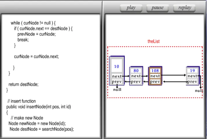
This learning case is designed to teach students the insert operation in a linked list data structure.
When node 20 is added to the linked list, the pointer references for nodes 108 and 22 must be
altered. The result of inserting node 20 before node 22 is shown in Figure 19. The code
visualization box in the Figure 20 shows the portion of the code used to rearrange the pointer
references to the nodes in the linked list after inserting the new node. This portion of the code is
deliberately changed. A bug is implanted in the program. Figure 21 shows the changes made to
31
Fig 19
Fig 20
public void insertNode ( int pos, int id) { Node newNode= newNode (id); Node destNode = searchNode (pos); if (destNode ==null || destNode ==first) {
newNode.next = first; first = newNode; }
else {
Node prevNode = searchPrvNode (destNode); newNode.next = destNode.next;
destNode.next = newNode; }
32
Fig 21
Because the pointer references are wrongly defined, the new node with id 20 is inserted between
nodes 22 and 19, while a correct implementation would have inserted the new node between the
nodes with ids 108 and 22 as shown in Figure 19.
Figure 22 shows the wrongful insertion result. The student should examine the insert
operation and identify that the node references have been wrongly assigned, resulting in the node
being added with incorrect position. After the animation is complete, a challenging multiple
choice question is presented to the student inside the description box. Figure 23 shows the
multiple-choice question for the test case.
To help the student answer the question, the button “Show the Animation” calls the
animation deployed with the correct code. This gives the student to understand a comparison
between the animations created based on the correct code and that based on the wrong code. public void insertNode ( int pos, int id) {
Node newNode= newNode (id); Node destNode = searchNode (pos); if (destNode ==null || destNode ==first) {
newNode.next = first; first = newNode; }
else {
Node prevNode = searchPrvNode (destNode); newNode.next = destNode.next;
destNode.next = newNode;
33
Fig 22
Ultimately the student will analyze the code responsible for the error. The student can
also attempt the multiple choice question at any point later in the debug mode by clicking the
“What’s wrong” button.
Fig 23
Learning Case #2
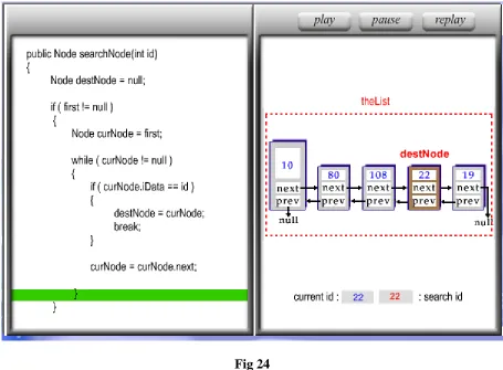
This test case is implemented to demonstrate the implementation of the search operation in the
doubly-linked list. A doubly-linked list has three main operations: Find, insert and delete. Figure
34
list. The animation for the find operation shows node 22 successfully returned as the search
result.
Fig 24
To create a test case, we have modified the code of the find operation on the doubly-linked list.
The modified code can be seen in Figure 25 below.
publicNode searchNode (int id) { Node destNode = null; if (first ! = null) {
Node curNode =first; while (curNode != null) {
if (curNode.iData == id) {
destNode = curNode.next;
break; }
curNode = curNode.next; }
}
35
Fig 25
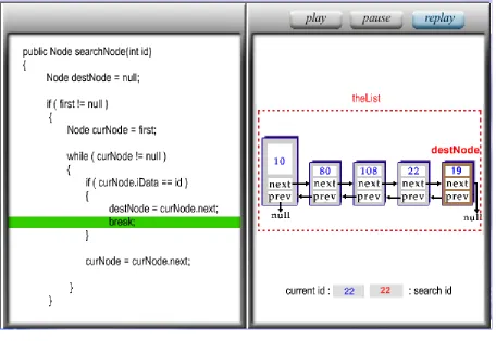
As seen in Figure 25, the code statement that determines the search result node is
modified. Due to the change in the code, the search result always returns the node next to the
original node that is being search for. Hence the animation now returns node 19 instead of node
22 as the search result. Figure 26 shows a snapshot of the animation with the planted error.
The student should examine the animation and identify that the search result statement
has been modified to give a wrong result. After the animation is complete, a challenging multiple
choice question is presented to the student inside the description box. Figure 27 shows the
multiple-choice question presented for this test case.
36
To help the student answer the question, the button “Show the Animation” calls the
animation deployed with the correct code. This gives the student to understand a comparison
between the animations created based on the correct code and that based on the wrong code.
Ultimately the student will analyze the code responsible for the error.
Fig 27
Learning Case #3
This test case is implemented to demonstrate the delete operation in a doubly-linked list. The
successful operation deletes the node 22 and reassigns the node pointer from node 108 to node
19. Figure 28 shows a snapshot of the animation in the doubly-linked list.
37
To implement the test case, we have implanted the bug in the code for the delete method. Figure
29 shows the code changes made to the delete operation of the doubly-linked list. As seen in
Figure 29, the code statement that identifies the node to be deleted (node 22) is deliberately
modified to delete node 108 instead of node 22. Figure 30 shows a snapshot of the doubly-linked
list delete operation with the planted error.
Fig 29
After the animation is complete, a challenging multiple choice question is presented to
the student inside the description box. Figure 31 shows the multiple-choice question. To help the
student answer the question, the button “Show the Animation” calls the animation deployed with
the correct code. This gives the student to understand a comparison between the animations
created based on the correct code and that based on the wrong code. public void deleteNode (int id) {
Node destNode = searchNode (id);
Node nxtNode = searchNode(destNode.next); if (destNode != null ) {
if (destNode == first ) { first = first.next; first.prev = last; }
else if (destNode == last) {
Node prNode = searchNode (destNode.prev); prNode.nxt = null;
} }
else {
Node prNode = searchNode (destNode.prev); Node oNode = searchNode(prNode.prev); destNode.prev = prNode.prev;
oNode.next = destNode; }
38
Fig 30
Fig 31
Ultimately the student will analyze the code responsible for the error. The student can
also attempt the multiple choice question at any point later in the debug mode by clicking the
39
Learning Case #4
This test case is implemented to demonstrate the delete operation in a circular-linked list. The
successful operation deletes the node 22 and reassigns the node pointer from node 108 to node
19. Figure 32 shows a snapshot of the animation in the circular-linked list.
Fig 32
public void deleteNode (int id) {
Node destNode = searchNode (id); if (destNode != null ) {
if (destNode == first ) { first = first.next; }
else if (destNode == last) {
Node prevNode = searchNode (destNode); prevNode.next = destNode.next;
} }
else {
Node prevNode = searchNode (destNode); prevNode.next = prevNode;
40
Fig 33
To implement the test case, we have implanted the bug in the code for the delete method. Figure
33 shows the code changes made to the delete operation of the circular-linked list. As seen in
Figure 38, the code statement that must reassign the pointer from node 108 to the next node
(node 19) after deleting node 22 is deliberately modified to point to node 108 itself. Figure 34
shows a snapshot of the circular-linked list delete operation with the planted error.
After the animation is complete, a challenging multiple choice question is presented to
the student inside the description box. Figure 35 shows the multiple-choice question. To help the
student answer the question, the button “Show the Animation” calls the animation deployed with
the correct code. This gives the student to understand a comparison between the animations
41
Fig 34
Fig 35
Ultimately the student will analyze the code responsible for the error. The student can
also attempt the multiple choice question at any point later in the debug mode by clicking the
“What’s wrong” button.
Learning Case #5
A stack data structure has two main operations: PUSH and POP. The push operation inserts the
new record on top of the previous records. The pop operation deletes the top record from the
stack. Hence a stack is a FIFO data structure. We have implemented a learning case to
demonstrate the implementation of the stack.
The code to implement a stack can be presented as in the Figure 36. In order to implant
an error to show the functioning of the stack in an incorrect manner, we replace the correct code
42
Fig 36
Using the PUSH operation, values 20, 30, 40 are pushed into the stack respectively.
Hence the value 20 will be at the bottom of the stack. For the value 20 to be able to be popped, it
is needed that the top most records with values 30 and 40 be popped first. However, with the
erroneous code in the POP method, the animation will show that the values 20, 30 and 40 are
popped in the same order as they are pushed on to the stack. This animation hence will Class stackPop {
public static void main (String [] args) { Stack theStack = new Stack(); theStack.push(20);
theStack.push(30); theStack.push(40);
while (!theStack.isEmpty ()) {
double value = theStack.pop (); System.out.println (value); System.out.println (“,”); }
} }
Class Stack {
private int maxSize;
private double [] stackArray; private int top;
private int front; public Stack (int s) {
maxSize = s;
stackArray = new double [maxSize]; top = -1;
front = 0; }
public void push (double j) { stackArray [++top] = j; }
public double pop () {
return stackArray [top--]; }
43
contradict the FILO ordering of the stack data structure. Figure 37 shows the snapshot of the
animation resulted from the wrongful implementation of the POP method.
Fig 37
It shows the instant when the first value in the stack is popped. The animation will show
that value 20 is popped first. This is an erroneous animation since this value at the bottom of the
stack, and that the first value to be popped must be value 40 according to FILO ordering of stack
data structure.
The student should identify the error in the stack implementation of the Pop method. We
challenge the student with the multiple choice question presented in the description box. Figure
44
Fig 38
To help the student answer the question, the button “Show the Animation” calls the
animation deployed with the correct code. This gives the student to understand a comparison
between the animations created based on the correct code and that based on the wrong code.
Ultimately the student will analyze the code responsible for the error.
Learning Case #6
This learning case demonstrates the implementation of the PUSH operation in a stack. Using the
push operation, values 20, 30, 40 are pushed into the stack respectively. Initially the size of the
stack is Zero. As the value 20 is added to the stack, the size of the stack is incremented by 1 and
the value 20 is stored at the top of the stack. As the values 30, 40 and 50 are added respectively,
the size of the stack is incremented by 1 each time and the values in it are pushed downwards
with the latest value to be added placed at the top of the stack.
In order to show the functioning of the stack in an incorrect manner, we replace the
correct code with the erroneous code inside the push method. Due to this deliberately planted
bug, the stack is shown to have a predefined size and the newly added values are added to the
bottom of the stack instead of being added at the top. This is a wrong implementation of the
45
Fig 39
Figure 39 shows the animation at the instant when the value 50 is being added to the
stack.
The animation resulting due to the planted error is shown in figure 40. As shown in the
46
Fig 40
The student should identify the error in the stack implementation of the Push method. We
challenge the student with the multiple choice question presented in the description box. Figure
41 shows the multiple-choice question.
Fig 41
To help the student answer the question, the button “Show the Animation” calls the
animation deployed with the correct code. This gives the student to understand a comparison
between the animations created based on the correct code and that based on the wrong code.
Ultimately the student will analyze the code responsible for the error.
Learning Case #7
This Learning Case demonstrates the preorder depth-first traversal algorithm in a binary tree. In
preorder traversal technique, the root node, the left child and the right child are traversed in the
respective order. The code to represent the Preorder traversal of a binary tree is given in Figure
42:
private void preOrder(node localRoot) { if(localRoot !=null) {
localRoot.displayNode(); preOrder(localRoot.leftChild); preOrder(localRoot.rightChild);
47
Fig 42
The order of the statements that control the traversal routes through the child nodes is modified.
The animation hence traverses through the right child before traversing through the left child.
The code of the traversal algorithm modified deliberately to plant the bug is shown in Figure 43:
Figure 43
A snapshot of the animation with the wrong implementation of the traversal order is shown in
Figure 44.
Fig 44
private void preOrder(node localRoot) {
if(localRoot !=null) { localRoot.displayNode();
preOrder(localRoot.rightChild); preOrder(localRoot.leftChild);
48
In this case, the animation is critical to students’ understanding because the problem is in the
process of computing rather than the output. We use the following multiple choice question to
challenge the student.
Fig 45
The correct implementation of the traversal order is presented to the student when the “Show the
animation button” is clicked.
Learning Case #8
By implementing this learning case, we would like to illustrate the single and double rotations in
an Avl tree. The code to implement the single and double rotations in an Avl tree is given in
Figure 46.
(Figure continued) //x – the new node to insert
// t – the node that roots the tree
private AvlNode insert (Comparable x, Avl Node t) { if (t == null)
t = new AvlNode (x, null, null); else if (x.compareTo (t.element) <0) {
t.left = insert (x, t.left);
if ( height (t.left ) – height (t.right) == 2) if (x.compareTo (t.left.element) < 0 ) t = rotateWithLeftChild (t);
else
49
Fig 46
By using the above code, we add nodes 65 and 70 in to the avl tree in the respective
order. Since the addition of node 65 imbalances the tree at node 55, the code performs single
rotation at node 55 to its right, thus balancing the tree. The addition of node 70 imbalances the
tree at node 90. So the code rotates the tree twice to perform double rotation. The first rotation is
made at node 50. The tree is rotated to the left at the node 50. The second rotation is made at
node 90. The tree is now rotated to right at node 90. Hence the avl tree is balanced using single
and double rotations. Figure 45 shows a snapshot of the animation of the code implementation.
To deliberately plant the bug inside the code of the avl tree insert algorithm, we alter the
condition for implementing the single and double rotation methods. The implications of the
resulting code change means that the rotation methods would not be invoked unless the height
difference between the left and right sub trees of any given node exceeds 3. The code modified to
deliberately plant the bug in the single and double rotation methods is shown in Figure 47. else if (x.compareTo (t.element) >0) {
t.right= insert (x, t.right);
if ( height (t.right ) – height (t.left) == 2) if (x.compareTo (t.right.element) < 0 ) t = rotateWithRightChild (t);
else
t = doubleWithRightChild (t); }
else ;
t.height = max ( height (t.left ), height (t.right)) +1; return t;
50
Fig 47
//x – the new node to insert // t – the node that roots the tree
private AvlNode insert (Comparable x, Avl Node t) { if (t == null)
t = new AvlNode (x, null, null); else if (x.compareTo (t.element) <0) {
t.left = insert (x, t.left);
if ( height (t.left ) – height (t.right) == 4) if (x.compareTo (t.left.element) < 0 ) t = rotateWithLeftChild (t);
else
t = doubleWithLeftChild (t); }
else if (x.compareTo (t.element) >0) { t.right= insert (x, t.right);
if ( height (t.right ) – height (t.left) == 4) if (x.compareTo (t.right.element) < 0 ) t = rotateWithRightChild (t);
else
t = doubleWithRightChild (t); }
else ;
t.height = max ( height (t.left ), height (t.right)) +1; return t;
51
Fig 48
As seen in the Figure 48, the statements that check for the imbalance of the tree are
modified and hence the tree would not perform single or double rotations when node 65 and 70
are added.
After node 65 is inserted, the tree gets imbalanced at node 55 as the height difference
between its left and right sub trees becomes 2. However, the tree is left imbalanced and followed
by the insertion of node 70. Figure 49 shows the snapshot of the animation resulting from the
wrongful code implementation.
Fig 49
The student must identify that the code does not perform any rotation when either node
52
presented to the student inside the description box. Figure 50 shows the multiple-choice
question.
Fig 50
By looking at the correct implementation of the single and double rotations, students can
understand and analyze the tree rotation in an Avl tree.
Learning Case #9 (a)
This learning case is implemented to teach students the implementation of double rotation in an
Avl tree. As explained in learning case #8, to balance the tree after adding node 70, we need to
rotate the tree in left and right directions respectively. This test case is implemented by altering
the code so that the tree rotates in left and left directions respectively instead of rotating in left
and right directions. Figure 51 shows a snapshot of the animation with the error in the
53
Fig 51
After the animation is completely over, the student is challenged with a multiple choice
question that tests his understanding of the tree rotations in the animations. Figure 52 shows the
multiple-choice question presented to the student after the animation is played.
54
In order to help the student identify the error, the “Show the animation” button calls the correct
animation. Student can hence understand the comparison between the correct and wrong
implementation of the directions in the tree rotations.
Learning Case #9 (b)
This learning case is implemented to teach the students the implementation of double rotation in
an Avl tree. This test case is implemented by altering the avl tree code so that the tree rotates in
right and right directions respectively instead of rotating in left and right directions. Figure 53
shows a snapshot of the animation with the error in the implementation.
After the animation is completely over, the student is challenged with a multiple choice
question that tests his understanding of the tree rotations in the animations. Figure 54 shows the
multiple-choice question presented to the student after the animation is played.
55
In order to help the student identify the error, the “Show the animation” button calls the correct
animation. Student can hence understand the comparison between the correct and wrong
implementation of the directions in the tree rotations.
Fig 54
Learning Case #9(c)
This learning case is implemented to teach the students the implementation of double rotation in
an Avl tree. This test case is implemented by altering the avl tree code so that the tree rotates in
right and left directions respectively instead of rotating in left and right directions.
After the animation is completely over, the student is challenged with a multiple choice
question that tests his understanding of the tree rotations in the animations. Figure 55 shows the
56
Fig 55
In order to help the student identify the error, the “Show the animation” button calls the
correct animation. Student can hence understand the comparison between the correct and wrong
implementation of the directions in the tree rotations.
Fig 56
57
Learning Case #10
This learning case is implemented to illustrate the dequeue operation in a Queue. A queue
follows a FIFO ordering for its operations. Figure 57 shows a snapshot of the animation of the
Dequeue operation in a queue. Using the enqueue operation, values 20, 30 and 40 are added to
the queue. The snapshot shows the value 20 currently being dequeued.
Fig 57
To implement the test case, the code used to implement the Dequeue operation is changed. The
58
Fig 58
Due to the change in the code, the values from the queue are dequeued in the FILO order.
Figure 59 shows the resulting animation with the planted error. class Queue
{
private int maxSize; private int[] queArray; private int front; private int rear; private int nItems; public Queue (int s) {
maxSize = s;
queArray = new int [maxSize]; front = 0;
rear = -1; nItems = 0; }
public void Enqueue (int j) {
if (rear == maxSize – 1) rear = -1;
queArray[++rear] = j; nItems++;
}
public int Dequeue() {
int temp = queArray [rear--]; nItems--;
return temp; }
59
Fig 59
Figure 59 shows the value 40 being dequeued from the queue. Since value 20 is the first
value to be enqueued to the queue, it should be dequed first. However, due to the planted error in
the code, the elements are dequeued in the FILO order. The student must identify the code
change that is responsible for the error in the implementation of the Dequeue method. The
student is presented with a challenging choice question. Figure 60 shows the
60
Fig 60
These sequences of steps require the full attention from the student. We believe getting
students’ complete concentration is important for their efficient learning.
Learning Case #11
A Hash Table uses a key-value pair to store information in a table. The key-value pair entered by
the user is stored in the location determined by the hashing function. The hashing function that
we have implemented for the hash table is:
Hash (key) = key mod 31
To deal with hash collisions, we applied linear probing technique to store the data
records. This learning casedemonstratesthe implementation of lookup, insert and delete
operations in a hash table. In this learning case, we have deliberately planted a bug to alter the
delete operation in the hash table.
In a hash table, whenever a data record is deleted, the corresponding empty index is
considered as empty for future insert operations and occupied for lookup operations. As seen in
Figure 61, when the data record at the index 18 is deleted, it will not leave any unwarranted
consequences for future insert/lookup operations. Figures 61 and 62 show a successful lookup
operation in the hash table. The key-value pair adams:125 is just deleted, but it is considered as
occupied for future search operations. Hence when we search for the record adams:567, it results
61
Fig 61
Fig 62
In the learning case, by planting the bug, we create an error during the delete process of a
62
a vacant record that prevents successful results for the next search operations. Hence when the
key-value pair is queried for lookup, it results in an empty result.
Fig 63
63
The student is challenged with a multiple choice question that tests his understanding of
the operations performed in the hash table. Figure 65 shows the multiple-choice question
presented to the student.
Fig 65
Learning Case #12
With this learning case, we intend to help students understand merge sorting algorithm. In merge
sorting, elements should be recursively be divided in to sub lists of half the size of the parent sub
list. This effectively means that the array must be divided to form sub lists of 2 elements each
(with only 1 group containing a single element in case total number of elements is odd). The
elements should then be sorted within their sub lists and then merged back and then sorted again
to finally give a sorted array of elements. Figure 66 shows the correct implementation of merge
64 Fig 66
In order to utilize this algorithm as a learning case, we have deliberately planted a bug in
the code. Due to this deliberately implanted bug, the unsorted list is divided only once resulting
in two sub lists of 4 elements each. Elements are then sorted within the respective sub lists and
merged back in to one sorted list of array.
This method of implementation does not reflect complete merge sorting. Figure 67 shows
the animation at the instant where the elements are divided in to two sub lists of 4 elements each
and sorted. This is an erroneous implementation of merge sorting because elements can only be
65
Fig 67
After the student examines the sorting animation, he must identify that the elements of
the array are not recursively divided in to sub lists of 2 elements each before being sorted. After
the animation is complete, a challenging multiple choice question is presented to the student
inside the description box. Figure 68 shows the multiple-choice question presented to the student
after the completion of the animation.
To help the student answer the question, the “Show animation” button calls the animation
deployed with the correct code. This gives the student a comparison between the animations
created based on the correct and that based on the wrong code and will also help the student
66
Fig 68
The student can also attempt the multiple choice question at any point later in the debug
mode by clicking the “What’s wrong” button.
4.2 Code Highlighting for Bug identification:
To assist students’ learning of algorithms through the animations and code visualization, we have
also implemented the code highlighting feature that allows the users to identify the bug in the
code.
In the debug mode, when the student analyzes the animation and finds a problem of the
animation, he can click the “Pinpoint to error” button and highlight the code lines that he thinks
are the reason for the error in the animation. Then he clicks “Check My Answer”. The animator
compares the highlighted code to the actual planted bug. If the user successfully identifies all the
lines of code that are responsible for the bug, the animator will give a success solute. Otherwise,
if he identifies the error partially, the animator alert says that he is partially correct. If he is not
able to identify the bug correctly, the animator shows the student the exact lines of bug code.
Figure 66 shows the user interface of this feature for the pop operation in a stack. After
the student analyzes the animation, he clicks the “Pinpoint to error” button and selects the lines
67
Fig 69
Once the user selects the erroneous lines, he then clicks “Check my answer” to find out if
he has successfully identified the error. In this example, since the user has identified all the
erroneous code lines, the animator gives him a success message as shown in Figure 70:
68
By providing this feature, we attempt to sharpen students’ capability in code analysis.
This feature hence provides a hands-on experience for the students to learn data structures
69
5. Learning Tool Implementation
The basic platform for the learning tool is the visual representations of the data structures
algorithms. The animations are designed in Adobe Flash environment using a combination of
Flash components and action script code. The compiled animation files (with .swf extension) are
dynamically loaded in to the Flex development environment. Each algorithm of the chosen data
structure is designed using Flash based components discretely using Adobe Flash professional
CS5. The animations are created using the frame based implementations. The Action script code
in Flash is used to adjust the timing and the interactive nature of the animations to the user
inputs. The motion implemented in the animations is defined using the motion tweening feature
available in FLASH.
The Flex AlgorithmAnimation.mxml serves as the main application which orchestrates
various animation files on the web server side. On the client side, the flash animation files are
loaded in the browser and are played using Adobe Flash Player plugin. The use of a combination
of Flash and Flex components in the development provides great advantages, especially in
presenting the animations in a swift and appealing manner.
Designing animations in Flash Professional CS5
In a frame-based animation, each frame can be manipulated using the layout controls in the
properties pane. ActionScript code snippets are used to guide and control the direction and
motion aspects of the animation. Additionally, changes to the timing aspects can be performed