IOT BASED VEHICLE THEFT DETECTION
Prakash B. Patel
Research Scholar
Information Technology Department D.Y.Patil University, Pune
Abstract: It is aforesaid that property crimes can reach ten million. Of these, the vehicle is flat-top within the steal list and is often control altogether components of the planet. Several new technological developments have developed and new techniques are upgraded to beat this drawback. The ways concerned in vehicle stealing recognition are noted to any or all, as well as shields, to interrupt the system and steal the vehicle. This paper displays a mechanism to reduce the vehicle stealing. This system provides protection by using RFID card and authorized key .RFID reader is attached to the car door and the entry is granted only if the card is authorized. Keypad is attached to the engine and it starts only when the authorized key is entered. It will make the continuous buzzer sound when vehicle has been stolen or moved without the owner's knowledge. System provides periodic updates for registered users through thingsspeak.com. This facility is provided by sending GPS location through GPS technology for stealing vehicle tracking.
Keywords: RFID reader, GPS, thingsspeak.com, Internet Of Things, vehicle tracking, Buzzer, Keypad.
1. INTRODUCTION
In recent years the vehicle stealing has been thought of as a big problem. The protection of the vehicle is needed. There are also some limitations and some of the more expensive ones. Therefore, an effective security vehicle is required.
This project detects about the vehicle theft. The arduino interface is an integral a section of dc motor and GPS. Wireless fidelity module is used to search out the vehicle's location through the Global Positioning System (GPS). GPS may be a navigation system that will be accustomed track the vehicle, and it provides the placement of the consumptive device altogether weather conditions. Victimization the GPS antenna provides the latitude and meridian of the device.
When we leave the vehicles outside, currently if the vehicle is taken, the D.C. motor starts and therefore the method on top of is over and also the info is distributed through the web content. This vehicle is employed as a vehicle thievery and rescue tool for thievery hindrance and following system.
The use of vehicles in today's time is obligatory. At identical time, vehicle steal day is that the quickest growing day in magnitude relation. As a result, vehicles protection from theft is very important. Prevention of cars is often done by providing authorization for owners and by building anti-theft system in vehicles.
2. EXISTING METHODS
The most usually used methods are beeps, alarms and biometrics. However these commercially on the market merchandise are terribly costly. It's easy to steal your vehicle by using a car buzzer. But when your car is away from you, you may not benefit from buzzer or alarm recognition.
Car alarm systems are used to help with various types of sensors such as pressure, tilt and shock & door sensors to prevent car robbery. However, these systems have some restrictions like peak worth, peak false warning rate and straight forward disposal. Recent developments in the PC software system and hardware for fixing this problem are to develop automobile industry reasonable authentication systems and automated biometrics primarily based identification. Several biometrics are used, like automatic face recognition, face expression, hand pure mathematics, handwriting and voice for identity and verification of people. But biometrics is not 100% accurate and requires unification and / or additional hardware and cannot be compromised once, if somebody learns it, you'll be able to continuously modification your password, however there's no thanks to modify your Iris, membrane or fingerprint. If somebody features a copy of their work, you can't do a lot of to remain safe.
3. PROPOSED METHOD
that use the date of exploitation to spot the vehicle, the planned system has exceeded the prevailing systems and system limits. This machine starts with Dc Motor, which suggests the door is unbarred exploitation the RFID card and the car door gets locked after few minutes. When the person enters the car he/she have to give the authorized key to start the vehicle. During the whole process, Arduino GPS is active and entire information including car door status motor status and with the assistance of GPS location and wireless fidelity module location will be sent to the owner by thingspeak.com. The entire mechanism is supported through a switch for owner satisfaction. The projected system diagram is shown in figure 1 below
Figure 1. Proposed System Block Diagram
3.1. Arduino mega:
The Arduino Mega is based on the microcontroller board, ATmega2560. It includes fifty four digital output / input pins (it can use fourteen PWM outputs), sixteen analog inputs, sixteen MHz crystal oscillator, four UARTs (hardware serial ports), an ICSP header, one USB association, a power jack and a reset button. This includes each item needed to assist the micro controller, attach it to a pc with a battery to start with only one USB cable or associate AC to DC adapter or battery. Since Mega additionally includes a plastic base plate to safeguard, don't be scared of accidental electrical conduction.
3.2. Buzzer:
3.3. WIFI module ESP 8266:
ESP8266 wireless fidelity module the self-controlling system on the chip that accesses the microcontroller to your wireless fidelity network. Each module has been arranged through an instruction set instruction code associate with the engine, which is often linked to the Arduino device and suggests that Wi-Fi can gain power. The ESP8266 module is heavily, and is growing anytime, the first expensive board in society.
3.4. DC Motor:
Very easy motor. D.C. motors have typically 2 leads, one is positive and the other is negative. If you connect this battery to the battery, motor rotates. If you modify the leads, the motor rotates in the opposite direction
3.5. Relay:
switch.
3.6. Keypad:
The buttons in the data input device are managed in rows and columns. A 3X4 data input device has four rows and three columns .A layer switch on every secret. In many lines each switch is connected to the opposite switches in line with a conductive trace under the pad. Each switch connects to the same method in most columns - one or all of the switch switches of the switch are combined with a carriage trace on the bottom. Each row and column will pin a pin.
3.7. GPS (Global Positioning System):
GPS is generally satellite primarily based navigation system. We have a tendency to use the NEO-6M GPS module as a result of it's appropriate for extending GPS receivers. It is a partial ceramic antenna. The 3V button is connected to the battery. Sometimes GPS works in anyplace within the world in weather conditions. A GPS receiver should secure a minimum of three satellite signals to estimate the second point (latitude and longitude).
3.8. RFID (Radio Frequency Identification):
releases an affiliate radio frequency signal through an associate antenna shown in Fig.
3.9. LCD (Liquid Crystal display):
3.10. FLOW CHART:
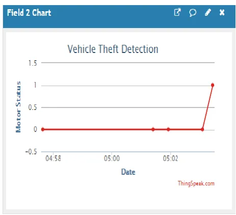
4. RESULTS AND DISCUSSIONS
Fig 4.2: Door status
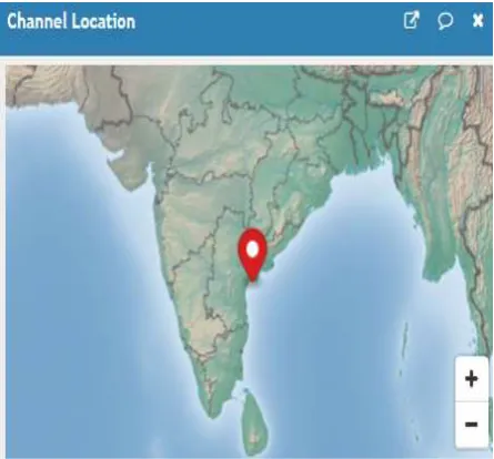
Fig 4.4: Channel Location
5. CONCLUSION
Vehicle theft, but not for violent crimes, has inflicted more damage to its victims in monetary value and secondary financial effects. The proposed system provides vehicle security and recognizes a very low cost efficient and efficient theft.
6. FUTURE ENHANCEMENT
The future scope of this paper is in the place RFID reader we can use biometric system. We can send alert message to the owner and nearby police station to track the vehicle by using Global Positioning System and Global System for Mobile.
REFERENCES
[1]Nagaraja, B.G.; Rayappa, R.; Mahesh, M.; Patil, C.M. and more authors, “Design and development of a GSM based Vehicle Theft Control System”, International Conference on Advanced Computer Control, 2009.ICACC ’09, Page(s): 240-245, 2013.
[2]D.Narendar Singh, K.Tejaswi (M.Tech), “Real Time Vehicle theft Identity and Control System Based on ARM 9”, International Journal of Latest Trends in Engineering and Technology(IJLTET), Vol.2,Issue-1 January2013, Page(s): 204- 245,2013.
[3]R.Ramani,S.Valarmathy,Dr.N.Suthanthira Vanitha,S Selvaraju, R Thangam,M Thiruppathi,”Vehicle tracking and locking system based on GSM and GPS”,I.J. Intelligent Systems and Applications,Vol.5, Issue-9 August 2013,Page(s):86-93,2013
[4]“A Vehicle is stolen every 13 mins in Delhi; rate up 44% since last year”-Timesofindia.
[5]Champa Bhagavathi.R , Gowri.B.R , Kasturi.R , Pooja.C,”vehicle theft Detection and Prevention Using GSM and GPS”, International Journal of Innovative Research in Computer and Communication Engineering Vol.4, Issue 5,May2016.
[6]B.G. Nagaraja, Ravi Rayappa, M. Mahesh, Chandrasekhar M. Patil, Dr. T.C.Manjunath, “ Design & Development of a GSM Based Vehicle Theft Control System ”
[7]Douglas V Hall,“Microprocessor and Interfacing-Programming & Hardware by”. [8]National motor vehicle theft reduction conference 2000, Conference Papers (Australia). [9]Stolen and Wrecked Vehicles Monitoring Program,CCMTA June 1994 (Canada).
[10]CCMTA Best Practice Models for Combating Auto Theft, Version 6.1, Oct. 2006, Anti Auto-Theft Project Group.
[11]Mill man & Garble, "Combinatorial Digital Circuits" and "Sequential Digital Circuits" of, Microelectronics, 2nd edition.