FPGA Alarm System Based on
Multi Temperature Sensor
https://doi.org/10.3991/ijoe.v13i05.7053
Yubao Xu
West Anhui University, Anhui, China [email protected]
Abstract—The purpose of this study is to achieve real-time acquisition and monitoring of temperature in large-scale industrial or agricultural production scene, and timely detect abnormal temperature. FPGA chip, multi temperature sensor and alarm control module three parts consist of FPGA alarm system ob-tained based on multi temperature sensor. Multi temperature sensor is used for the acquisition of relevant temperature signal in the production site, and the transmission of the collected data through the way of digital signal chip to the FPGA chip for further processing. The FPGA chip is responsible for the param-eter setting, the temperature signal acquisition and the threshold comparison and so on, and according to the data processing result, it can send out the nor-mal response control signal to the alarm module. The alarm module contains the pre-warning lights and the alarm device that it can receive the control signal and realize alarm response. The results showed that the test in planting flowers in greenhouse showed that the system is sensitive in response and small in error of temperature acquisition, in accordance with the requirements for use. As a re-sult, the system can be widely used in the temperature monitoring in the pro-duction scene, suitable for being promoted in a variety of occasions needing for monitoring the temperature.
Keywords—temperature sensor, alarm system, FPGA, temperature monitoring
1
Introduction
production departments and the production links put forward more and more require-ments on the accuracy of temperature monitoring, and the traditional temperature sensor has been unable to meet the needs of people's lives.
Throughout the current temperature monitoring system using intelligent tempera-ture sensor DS18B20, the vast majority make use of micro-controller development. According to the FPGA chip with various I/O pins, static, dynamic, and repeatable programming and so on characteristics in the reconstruction of the system, this study attempts to use FPGA and DS18B20 temperature sensor combination to conduct the design of temperature monitoring alarm system. In addition, with the expanded func-tion and flexibility of electronic system developed by FPGA chip, it provides a pow-erful guarantee for the system function upgrade in the future.
2
State of the art
FPGA (Field—Programmable Gate Array) is a field programmable gate array, which is the product of further development on the basis of PAL, GAL, CPLD and other earlier programmable devices. In the field of application specific integrated circuit (ASIC), FPGA as a semi-custom circuit, greatly solves the problem of lack of flexibility to upgrade the original custom circuit. At the same time, it overcomes the shortcomings of limited circuit number for the earlier programmable gate. FPGA chip is mainly composed of 7 parts, which respectively can be summarized as: the basic programmable logic unit, programmable input / output unit complete clock manage-ment, embedded block RAM, rich wiring resources, embedded underlying functional unit and embedded hardware module [3].
Available devices used in temperature acquisition are mainly analog devices (thermistors, transistors, etc.) and digital temperature sensor. Most of the traditional methods take thermal resistance and thermocouple as temperature sensitive compo-nents, but they have the disadvantages of poor reliability, low accuracy and low accu-racy [4]. Most of temperature measurement and control system composed of the tem-perature sensor have two major shortcomings: first, they need a large number of con-nections to send the scene sensor signal to the acquisition card, the wiring construc-tion is troublesome, and the cost is also high; second, what on the transmission line is the analog signal, vulnerable to interference and loss. While the new intelligent tem-perature sensor DS18B20 model has high precision, low price, simple network, no zero drift, no A/D conversion and so on advantages. Although it has defects in corro-sive than the optical fiber sensor, it improves the anti-corrosion ability by applying a method of metal packaging.
over-come this problem, this paper uses a high-precision digital temperature sensor DS18B20. The characteristics of DS18B20 temperature sensor comprises a power supply range (3.0V~5.5V), which can use the signal line parasitic for power supply, provide the temperature measurement precision with 9 to 12 bits, the temperature measurement range of -55 DEG C to +125 DEG C, and can work on a same single bus. The characteristics of the FPGA chip is directly facing to the user, the system software and hardware testing achievement is convenient and rapid, with very large flexibility and so on [6]. To sum up, through the effective combination of the two, it is very suitable for the requirements of a variety of system applications for hardware and software system for scalability, cost control and the development of simple structure. Based on the above reasons, this paper proposes a new method of using DS18B20 temperature sensor and programmable logic device FPGA to achieve the temperature monitoring system.
Temperature control is widely used in various fields of social life, such as home appliances, automobiles, materials, power electronics and so on. According to the application and the required performance indicators, commonly used control circuit is different. Many scholars have studied this aspect.
Lang Yue and Tong Shoufeng propose a demodulation system for fiber Bragg grat-ing (FBG) temperature sensor design. The results show that the average temperature error of the system is less than 0.2 in the measurement experiment. It can realize
the real-time sampling and processing of the four signals.
Combined with the characteristics of FPGA, Zheng Lijuan, Wang Mei, Wang Ning take the intelligent temperature sensor DS18B20 as a temperature acquisition device. Through the collection, storage, display and serial transmission of the four tempera-tures, they make the hardware, software and interface design of the system. Finally, they completed the entire temperature collection system. The advantages of the sys-tem are simple and reliable and strong anti-jamming capability.
In harsh environments, especially strong electromagnetic interference environment, the embedded system based on MCU architecture is very prone to failure or even out of control. In order to solve this problem, Liu Zhibin and Jiang Li have designed a highly reliable temperature acquisition system based on FPGA and temperature sen-sor control. The experimental results show that the newly designed temperature ac-quisition system runs faster and more stable.
can be widely used in the temperature monitoring in the production scene, suitable for being promoted in a variety of occasions needing for monitoring the temperature.
3
Methods
3.1 System hardware design
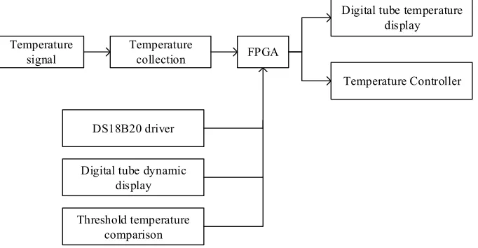
Figure 1 is the system structure diagram of temperature controller designed in this study. First of all, the temperature signal outputs the digital signal through the tem-perature sensor DS18B20 acquisition, and then the digital signal output is sent to FPGA for the processing (divided into three parts). Binary signal by decoding input is converted into 10 decimal signal, to display in the digital tube, and the binary signal input is sent to the comparator, to compare with the set threshold signal. According to the comparison result, control the level of the output electric level, and achieve the role of controlling the external unit components.
Temperature
signal Temperature collection FPGA
Digital tube temperature display
Temperature Controller
DS18B20 driver
Digital tube dynamic display
Threshold temperature comparison
Fig. 1. Temperature controller system structure
FPGA based temperature sensing alarm system, from the hardware module, can be divided into: temperature alarm module, temperature display module, configuration circuit module, clock circuit module, configuration module, clock circuit module, temperature alarm control system setting module, and system power supply module. The various modules cooperate together, to provide hardware basis guarantee for the realization of the temperature alarm function.
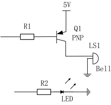
Fig. 2. Temperature alarm module schematic
Cyclone FPGA chip configuration can be divided into active configuration mode (AS), passive configuration mode and JTAG configuration mode. This research de-sign system uses JTAG mode.
Temperature sensor alarm system design circuit original clock output frequency is 50MHz, and the system clock alarm module schematic is shown in figure 3.
VCC OUT GND NC
CLK C10
0.1uF
3.3V
Y1 4 2
3
1
R
Fig. 3. Clock circuit module schematic
3.2 System software design
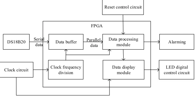
Figure 4 is the architecture block diagram of the designed temperature sensing alarm system.
DS18B20
FPGA
Data buffer Data processing module
Clock circuit Clock frequency division Data display module
Alarming
LED digital control circuit Reset control circuit
Serial
data Parallel data
Fig. 4. Temperature sensing alarm system architecture diagram
As shown in figure 4, there are data processing module, temperature display mod-ule, clock divider modmod-ule, and data buffer module in the FPGA. The data processing module completes the temperature threshold comparison, the temperature threshold parameter setting as well as the reset function. Temperature display module completes the LED digital display output function. Clock frequency divider module realizes the frequency reduction function. The data buffer module realizes the receiving of serial data received by DS18B20 and completes the parallel data output function.
The data processing module completes the temperature data threshold setting, the comparison, as well as the LED code output function. Data source of data processing module includes data cache module and system key control module, wherein the 12-bit binary code provided by the data cache module is real-time temperature trans-coding [8]. The data processing module compares the received data with temperature threshold parameters preserved in registers in advance, and when the conditions are met, trigger the corresponding response operation.
The temperature display module, after receiving the 14-bit binary code provided by the data processing module, will complete the temperature display output of the code, divided into 4-bit, and 8-bit two binary codes. Temperature display module input port contains: clock signal, reset signal, and 14-bit binary temperature signal. The output module of the temperature display module includes: 4-bit, 8-bit, and two binary tem-perature signals.
and the development mainly adopts the conditional delay to make frequency division processing of the original frequency.
The flow chart of temperature acquisition for the data cache temperature acquisi-tion module is shown in figure 5.
Start
The DS18B20 is initialized
Issue search ROM command
Start the data conversion of the DS18B20
The DS18B20 is initialized
Send a match ROM command
Send the DS18B20 serial number
Send Read Buffer command
Read the temperature of the matched DS18B20
Online DS18B20 access is complete Y
N
Fig. 5. Temperature acquisition flow chart
4
Experiment
Fig. 6. System entity diagram
4.1 Experiment process
The functional test of the system is carried out in a planting greenhouse with the length of 50m and the width of 15m. The layout of temperature sensor and alarm is shown in figure 7.
Temperature
Sensor1 Temperature Sensor2 Temperature Sensor3 Temperature Sensor4 Temperature Sensor5
Temperature Sensor6 Temperature
Sensor7 Temperature
Sensor8 Temperature
Sensor9 Temperature
monitoring alarm
Fig. 7. The arrangement of temperature sensor alarm system in flowers Greenhouse
Instruction mode specific test methods are as follows:
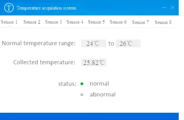
The 9 terminal temperature acquisition nodes, according to the average distribution principle, are placed in flowers greenhouses. Set to acquire the temperature once eve-ry 10 minutes. For testing whether the sensitivity and alarm function of the system temperature acquisition is normal, the normal temperature is set to 24 DEG ~26 DEG [9]. In the actual application, according to the actual situation, we can set the acquisi-tion time interval and the normal temperature range.
4.2 Experimental results and discussion
In the experiment, the temperature acquisition module is used to measure the tem-perature, and then the temperature is measured by the conventional method in the same position.
The system temperature acquisition interface is shown in Figure 8.
Fig. 8. Temperature acquisition system interface
Table 1. System function test results
Acqui-sition time
No. 1 sensor No. 4 sensor No. 8 sensor
Ter-minal acqui-sition Con- ven-tional acqui-sition Sys-tem feed-back Ter-minal acqui-sition Con- ven-tional acqui-sition System feed-back Ter-minal acqui-sition Con- ven-tional acqui-sition Sys-tem feed-back
9:00 26.13 26.06 Alarmed 26.08 26.02 Alarmed 26.08 26.11 Alarmed
9:10 25.51 25.45 No 26.16 26.18 Alarmed 26.06 26.10 Alarmed 9:20 25.53 25.55 No 25.92 26.01 No 25.79 25.84 No 9:30 25.82 25.85 No 26.15 26.18 Alarmed 25.87 25.91 No
9:40 26.01 25.97 Alarmed 25.97 26.03 No 25.79 25.75 No
9:50 26.02 26.03 Alarmed 26.03 26.01 Alarmed 26.01 26.03 Alarmed
10:00 25.91 25.97 No 25.96 25.98 No 26.03 26.04 Alarmed
10:10 26.20 26.18 Alarmed 25.95 25.98 No 26.06 26.09 Alarmed
10:20 26.22 26.25 Alarmed 26.08 26.07 Alarmed 25.98 25.94 No
10:30 25.94 26.10 No 26.18 26.18 Alarmed 25.89 25.87 No
As can be seen from table 1, the system sends out an alarm when the collected temperature exceeds the preset range, indicating that the system operates normally.
! " # $ % & ' ( ) *+,"
*+,! +,+ +,! +,"
Av
era
ge t
emperat
ure d
iff
ere
nce
/
The sensor number
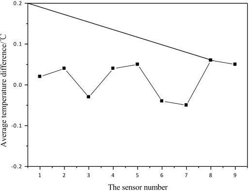
-Fig. 9. The average difference between system acquisition temperature and traditional method temperature
As can be seen from Figure 7, the designed FPGA alarm system based on multi temperature sensor has accurate temperature acquisition, and compared with the tem-perature measured by the traditional method, the error is within ±0.1 DEG C, able to effectively avoid that the system sends out the wrong alarm.
At present, the intelligent flowers greenhouse temperature control is still in the ini-tial stage in application. Because of its relatively high economic cost, it has not been widely used, but we have reason to believe that, with the development of technology, in the future, intelligent temperature monitoring system must be able to get a good application and development.
5
Conclusion
The universality of the system is strong that it can be used in most of the occasions needing for monitoring the temperature, such as grain, coal mines, road or some envi-ronment with harsh conditions of production. Although due to the cost, the automatic temperature monitoring system has not been widely used in China's industrial produc-tion, with the development of technology, automatic temperature monitoring system is bound to be the future mainstream of temperature monitoring, and has broad appli-cation prospects.
6
References
[1]Abdulmunem, A. S. M. Q., & Kharchenko, V. S. (2016, August). Availability and Security Assessment of Smart Building Automation Systems: Combining of Attack Tree Analysis and Markov Models. In Mathematics and Computers in Sciences and in Industry (MCSI), 2016 Third International Conference on (pp. 302-307). IEEE.
[2]Ahmad, N., Rifen, A. A. M., & Wahab, M. H. A. (2016, November). AES Cardless Auto-matic Teller Machine (ATM) Biometric Security System Design Using FPGA Implemen-tation. In IOP Conference Series: Materials Science and Engineering (Vol. 160, No. 1, p. 012113). IOP Publishing. https://doi.org/10.1088/1757-899X/160/1/012113
[3]Babu, N., Noorbasha, F., & Gunnam, L. C. (2016). Implementation of high security cryp-tographic system with improved error correction and detection rate using FPGA. Interna-tional Journal of Electrical and Computer Engineering, 6(2), 602.
[4]Constantin, J., Houlmann, R., Preyss, N., Walenta, N., Zbinden, H., Junod, P., & Burg, A. (2017). An FPGA-Based 4 Mbps Secret Key Distillation Engine for Quantum Key Distri-bution Systems. Journal of Signal Processing Systems, 86(1), 1-15. https://doi.org/10.1007/s11265-015-1086-1
[5]Dafico Pfrimer, F. W., Koyama, M., Dante, A., & Chagas Ferreira, E. (2014). A closed-loop interrogation technique for multi-point temperature measurement using fiber bragg gratings. Journal of Lightwave Technology, 32(5), 971-977. https://doi.org/10.1109/ JLT.2013.2295536
[6]Kasap, S., & Redif, S. (2014). Novel field-programmable gate array architecture for com-puting the eigenvalue decomposition of para-hermitian polynomial matrices. IEEE Trans-actions on Very Large Scale Integration Systems, 22(3), 522-536. https://doi.org/10.1109/ TVLSI.2013.2248069
[7]Neji, N., Jridi, M., Alfalou, A., & Masmoudi, N. (2016). Enhancement of DRPE perfor-mance with a novel scheme based on new RAC: Principle, security analysis and FPGA implementation. Optics Communications, 360, 73-82. https://doi.org/10.1016/j.optcom. 2015.10.013
[8]Ranaweera, M., & Kim, J. S. (2016). Cell integrated multi-junction thermocouple array for Solid Oxide Fuel Cell temperature sensing: N+ 1 architecture. Journal of Power Sources, 315, 70-78. https://doi.org/10.1016/j.jpowsour.2016.03.002
[9]Rao, I. R. S. N., Krishna, B. M., Shameem, S., Khan, H., & Madhumati, G. L. (2016). Wireless Secured Data Transmission using Cryptographic Techniques through FPGA. In-ternational Journal of Engineering and Technology (IJET), e-ISSN, 0975-4024.
7
Author
Yubao Xu is Associate Professor at West Anhui University, Anhui, China ([email protected]).