20th International Conference on Structural Mechanics in Reactor Technology (SMiRT 20) Espoo, Finland, August 9-14, 2009 SMiRT 20-Division 8, Paper 1622
Aging problems and residual life time evaluation of the WWER-1000 MW
containment shell structure
Dimitar Stefanov
aa
Bulgarian Academy of Sciences, Central Laboratory for Seismic Mechanics and Earthquake Engineering, Sofia, Bulgaria, e-mail: [email protected]
Keywords: Aging problems, Containment, Prestressing system, Monitoring
1
ABSTRACT
The main goal of this paper is to generalize the specific aging problems and the residual life time evaluation of the WWER-1000 MW containment shell reinforced concrete structures of Unit 5 and 6 in Kozloduy NPP, Bulgaria. First of all the different factors and degradation mechanisms are investigated. Several types of in situ and laboratory tests are performed for specific elements of the civil structures. Based on these results and on the available technical information an evaluation for the condition of the reinforced concrete structure is done. Several techniques for investigation of the concrete and steel are recommended. Prescriptions are given for the periodical inspections of the important parts and details of the containment shell structures. Some specific issues are considered for the instrumental monitoring and the control of the aging mechanisms. Special attention is paid to the monitoring of the structure – monitoring of the stress and strain state of the concrete and the monitoring of the prestressing system. A concept is recommended for the future development and modernization of the monitoring systems. Proper measures are suggested for reducing the aging effects which are the basis of the maintenance program for these structures.
2
INTRODUCTION
There are two units of type WWER-1000 MW which are in operation more than 20 years in NPP Kozloduy, Bulgaria. Some specific aging problems appeared during that time and different technical solutions are applied. It is useful to share this experience with the engineering community and to discuss the proper measures for the future exploitation.
In the scope of big project for analysis of engineering safety of the containment structures of units 5 and 6 in NPP Kozloduy some specific issues are considered which are related to aging problems, residual life time (RLT) evaluation, monitoring program and aging management program.
In order to assess the residual life time of the containment structure a complex analysis of big amount of information is done. The process consists of several stages:
•Condition of concrete and reinforcement;
•Evaluation of containment reinforced concrete structure; •Condition of protective concrete and drainage system; •Evaluation of prestressing system.
3
DESCRIPTION OF THE STRUCTURE
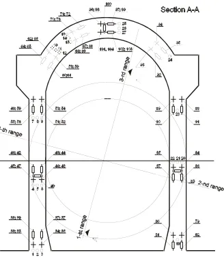
The VVER 1000 reactor building is a spatial structure composed by four main parts – foundation block, containment structure, inner RC structure and auxiliary surrounding structure. The four sub-structures are integrated by a thick reinforced concrete with thickness of 2.4 meters on level +13.20. Internally of the containment there is a heavy reinforced concrete structure starting from +13.20 aimed to support and protect the primary mechanical components and equipment. Externally, the containment is surrounded by reinforced auxiliary structure with plan dimensions 66.0 x 66.0. An essential part of the reactor building is the containment. The containment structure of WWER-1000 reactor is composed by a pre-stressed reinforced concrete cylinder and a spherical dome, both connected by a massive ring. The containment is mounted on the thick plate on elevation +13.20. The main geometrical dimensions of the containment are: height of the cylinder – 44m; diameter – 45m; relative elevation at the top of the dome - +66.45m; thickness of the cylinder wall – 1.2m ; thickness of the dome wall – 1.1m. The internal surface of the containment and the integration plate on elevation +13.20 are covered by a steel liner, 8mm thick, to form a hermetic volume. The containment is pre-stressed by 132 tendons, arranged helicoidally in the cylinder and orthogonally in the dome. The design pre-stressed force is 9810 kN for each tendon. Cross section of reactor building is given in Fig.1. Fig.2 illustrates the upper part of the shell structure above the auxiliary building.
Figure 1 Schematic view of the reactor building
4
SPECIFIC PROBLEMS WITH THE PRESTRESSING SYSTEM
The main problems of the containment shell structures are connected with the original prestressing system. In the original design every one of the prestressing tendons consists of 450 steel wires with diameter 5 mm (steel B-II). The tendons are installed in plastic tubes (which are placed before casting of the concrete). The plastic tubes are not injected and replacement and post tensioning are possible.
During the exploitation of the units 5 and 6 several specific problems are defined which did not allow the realization of the design force at many tendons:
•Complete break of the whole tendons during the process of prestressing or without any external loading during normal exploitation;
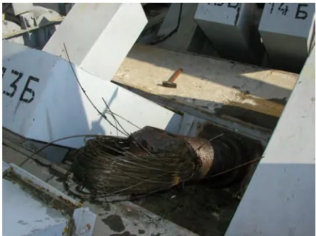
•Break of individual wire at forces significantly lower than the design value; •Exhausting the tread of the anchor screw before reaching the designed force. Some of these cases are illustrated in Figures 3 and 4.
Figure 3 Breaking of dome tendon
Figure 4 Breaking of cylinder tendon
After a detailed analysis it is established that the design prestressing system has some special features which lead to gradual loss of prestressing force and prevent reaching the designed force of 9810 kN. The most essential features are:
the connections lead to prolongation and redistribution of the forces in wires. Because of this some wires are overloaded and breaking occurs at load significantly lower than the designed one. 2. The second unfavourable factor is reducing of the characteristics of the wires during their plastic
deformation in the process of tendon preparation.
3. The third factor for overloading and breaking of some wires is impossibility of regular arrangement on the anchor detail.
As a result of comprehensive analysis of the behaviour of the system for a long time a new prestressing system was proposed and successfully implemented.
5
RESIDUAL LIFE TIME EVALUATION
5.1
Condition of the concrete and reinforcement
The condition of the concrete can be evaluated as very good. From visual inspections of the drilled concrete core samples is established that they are from healthy compact concrete, without visual cracks, caverns or other defects. The concrete quality is evaluated by nondestructive (in situ) and destructive (in laboratory) methods. The received high values for the compressive strength confirm that the concrete is in very good condition.
The depth of the available carbonation is small and there is no danger for the reinforcement. These results show that the concrete is able to ensure the reliable protection of the reinforcement for a long time. The improvement of the isolation properties of the protective concrete on the dome of the structure will reflect favourably on the residual life time and will slow up the process of the carbonation in the future.
The condition of the reinforcement is good. According to the results from the destructive tests only at some location there are indications for possible corrosion. The preventive measures for reliable isolation of concrete surfaces will reflect favourably on the eventual possibilities for corrosion of reinforcement in the future time.
5.2
Evaluation of the reinforced concrete structure of the shell
The concrete is able to protect the reinforcement. The depth of the carbonation is not dangerous for the reinforcement. The structure is protected from atmosphere influences by protective concrete on the domes and steel liner on the cylinder shells. A proper maintenance of these protections will guarantee the exploitation without problems many years.
Based on the results received from the in situ measurements and laboratory tests the condition of the concrete structure can be evaluated as very good.
5.3
Condition of protective concrete and drainage system
The protective concrete and drainage system are important for the rest life time evaluation. The general condition of the protective concrete is good but there is a need of rehabilitation activities in two directions. The first one is reliable isolation of the joints. The isolation material in the joints works in very unfavourable condition. It is directly exposed to atmosphere influence and naturally ages quickly. The second direction is the area rehabilitation of the external surface of the dome protective concrete.
The condition of the drainage system is good. There is a need of some repair activities to ensure reliable drainage of the anchor through the cylindrical tendons, painting of the steel liners and reliable isolation of cylindrical shells from rain water behind the protective corrugated sheet iron.
5.4
Evaluation of the prestressing system
Figure 5 Anchor detail for tendon type 551 5.2 mm
All disadvantages of old prestressing system are avoided in the new one. The value of the prestressing force can reach the designed value of 9810 kN in the new tendons. Several lift up tests are performed and the results confirmed the very good behavior of the tendons. The relaxation is very small, the losses in prestressing force are about 300 kN for 7 years. Until now there is no necessity of additional prestressing of the new tendons.
The final assessment is that the prestessing system is in very good condition, completely upgraded and can assure a reliable prestressing of the reinforced concrete shell structure for long period of time. The prestressing system does not limit the residual life time of the containment structure since all important elements like tendons and anchor details can be replaced if it is needed.
5.5
Conclusion for residual life time for containment structures
The final conclusion for residual life time for containment structures is done on the base of complex analysis of all available data. They include the results from in situ and the laboratory tests, visual inspections and analytical investigations. The residual life time for the main containment structures is evaluated in the range of 45-50 years for unit 5 and in the range of 50-55 years for the unit 6. During this period a precise implementation of monitoring program and aging management program should be fulfilled.
6
MONITORING PROGRAM FOR THE CONTAINMENT SHELL STRUCTURE
6.1
Monitoring for stress and strain state of the containment structure
Originally the containment structure is equipped with monitoring system based on strain-gauges (vibrating wire) mounted inside the cross-sections during the construction. There are three types of sensors – PSAS (strain gauges at the reinforcement), PLDS (strain gauges at the concrete) and PTS (temperature sensors at the concrete). The location of the sensors is given in Fig.6.
According to the original monitoring procedure the stressed condition of the containment is monitored by the sensors mounted in the structure. The results obtained from all measured locations are averaged to one parameter called “mean integral stress” which describes the global structural response. Additionally, periodical lift-up tests are performed to obtain the actual tendon forces. Using the collected data from the monitoring system and the lift-up tests during the exploitation of the structure a correlation factor was calculated which correlates the “mean integral stress” to the average pre-stressed level at the tendon system at every moment. During the years the number of working sensors continuously decrease.
The system was designed to function in the first 3 to 5 years from the exploitation of the units. The final assessment for the system is that it is not reliable enough. In spite of high level of amortization of the system, it is still important for the future exploitation of the structures because of the following reasons. The presence of working sensors (even a few numbers) located in the depth of the reinforced concrete structure gives the possibility for direct evaluation of the stresses and strains in the structure. The data from the system (measured deformations) will always help the calibration and verification of numerical models etc. If in the future a new system would be installed the data from the old one will be used for tuning. That’s why is advisable to foresee measures for re-evaluation and rehabilitation of the system which will stabilize the work of the system in the future.
6.2
Monitoring of the prestressing system
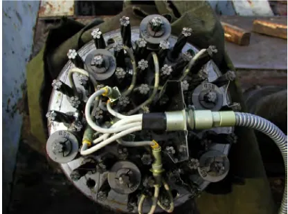
The new pre-stressing system is equipped with permanent monitoring system. Six cylindrical and four dome tendons at each unit are equipped with permanent monitoring system. The force at six cables at every controlled tendon is measured, generally 60 cables. Fig.7 shows one tendon with six dose-anchors. The average force multiplied by 55 is considered to be the integral tendon force.
Figure 7 – Tendon 55 Ø 15,2 with six dose-anchors
The dose-anchors are connected through cables to the central recording station. In this way the force in the chosen cables and the entire tendon are continuously measured during the pre-stressing process and during the unit exploitation. The measured data are recorded at server. Using special software the data are available for access and manipulation from the users.
6.3
General evaluation and perspectives for future development of the monitoring of the
containment structure
The present monitoring of the containment has the following disadvantages:
• the monitoring of concrete stresses is based on old and seriously damaged system and therefore can not be reliable;
• the monitoring of the pre-stressing system is based on discrete measuring of only 7.5% of the pre-stressing tendons. Also the tendon force is measured only at the end of the tendon and therefore the force distribution through the length can not be obtained.
The following stages in the monitoring development are proposed to the NPP:
1. First stage – Upgrading of the present tendon monitoring system with sensors along the length of one or two tendons. Also assessment and eventually rehabilitation of the original monitoring system.
2. Second stage – Development and implementation of new tendon monitoring system which can measure the integral force at every tendon. The installation of this system can be done gradually and can be combined with the periodical lift-up tests (to unload the anchor screw and for verification of the system).
3. Third stage – Development and implementation of new monitoring system for the stress condition of the containment. It can be based either on direct measurement of the stresses and strains at the concrete or on dynamic monitoring based of measurement of micro vibration and subsequent conclusions for the stress condition.
7
AGING MANAGEMENT PROGRAM
The aging management program for the containment structure is composed from several main components [1,2,3]:
•Data base for structural materials;
•Visual inspections in order to control the condition of the containment structure; •Control on aging processes and reduction of aging effects;
•Recommendations for proper measures for limitation of aging.
7.1
Data base for structural materials
The main structural materials used in containment are concrete, reinforcement steel and steel for structures shaped the anchoring of tendons. The tendons are made from special steel. All available information for material characteristics is advisable to collect in one common data base. It includes the data from the first moment of construction of the structure, all upgradings, repairs and the data from tests (destructive and nondestructive). The big advantage of common data base is the possibility to follow the changes of different characteristics during the time – from the early construction of the containment, passing through different periods of its exploitation until the last moment.
The data base must be open, to allow addition of new characteristics since the methods for instrumental investigation have significant development in the last years. New equipment comes into practice which allows the measurement of some new parameters of structural materials.
7.2
Visual inspections in order to control the condition of the containment structure
The control of the condition of containment structure is conducted by periodic visual inspections. The main goals of the inspections are:
• Establishment of existing defects in the structure like scattered concrete, damaged concrete cover, reinforcement corrosion;
•Detection of cracks in reinforced concrete elements;
•Registration of leakages, inspection of hydro-insulations and drainage systems;
•Choice of suitable places for experimental tests for evaluation of mechanical characteristics of materials (if necessary).
A detailed analysis is done after inspections of all gathered information. It includes evaluation of significance of the detected defects for aging of the whole structure and taking the decisions for proper action (conduction of additional investigations or directly following to repair activity).
7.3
Control on aging processes and reduction of aging effects
The control on aging of the elements of the prestressing system is carried on in two directions - appearance and development of corrosion and reduction of prestressing force in tendons.
7.4
Recommendations for proper measures for limitation of aging
After analysis of detected defects and evaluations of the residual life time of the containment structures some recommendations for proper measures for limitation of aging are made.
The succession of recommended measures depends on their relative importance for residual life time of the structure. A given priority is suggested for every measure. A three degree scale is used as follows:
•Priority 1: the measure is from first rank importance for RLT of the containment structure. The implementation of the measure must be realized as soon as possible (immediately when is practically possible).
•Priority 2: the measure is important but the implementation can be realized in period of 1 - 1.5 years;
•Priority 3: the measure is important in long term period and the implementation can be realized in period of 1.5 - 2 years.
8
CONCLUSIONS
Analysis of aging processes is carried out and the residual life time of two containment structures is evaluated. For this purpose different factors and aging mechanisms are considered. The data from the in situ and laboratory tests are analyzed and summarized. Based on the received results and available technical information an evaluation for the condition of the reinforced concrete structure and prestressing system is done.
Different parts from the Program for monitoring and Aging Management Program are examined.
Specific issues for instrumental monitoring and control of aging processes of containment structure are commented. A concept for future development and modernization of monitoring systems is proposed. Proper measures are suggested for reduction of unfavourable aging effects. These measures represent very important part of Maintenance Program.
ACKNOWLEDGEMENTS
This study has been developed under a contract between RISK ENGINEERING LTD and the NPP KOZLODUY JSC. The support of the NPP's personnel for collecting of monitoring data and other technical information and especially the efforts of Mr. M.Milanov and Mr. S.Danailov are gratefully acknowledged.
REFERENCES
1. NUREG/CR-6424, Report on Aging of Nuclear Power Plant Reinforced Concrete Structures.
2. IAEA SAFETY STANDARTS, Draft safety guide DS382, 2007, Ageing Management for Nuclear Power Plants.