Jurnal Teknologi, 43(D) Dis. 2005: 61–80 © Universiti Teknologi Malaysia
PERFORMANCE OF SERIALLY CONCATENATED CHANNEL CODING WITH SPACE TIME BLOCK CODING IN OFDM
TRANSMISSION SYSTEMS
MULADI1, N. FISAL2 & S. K. YUSOF3
Abstract. It is well known that space-time diversity using space-time coding (STC) is an effective technique to improve wireless communication performance. STC was designed for flat fading channel and consists of space-time trellis code (STTC) and space-time block code (STBC). STTC has provided diversity gain and coding gain in the cost of decoding complexity. On the other hand, STBC only provides diversity gain but simple in decoding complexity. Thus, in this paper, we proposed serially concatenated Bose-Chauduri Hocquengheim (BCH) code with STBC from orthogonal design (STBC-OD) scheme to provide diversity gain and also coding gain in the system. We incorporated OFDM transmission system onto our proposed scheme to maintain the performance over multipath selective fading channels. Performance of the system was investigated when M-ary phase shift keying (M-PSK) modulation was used for full-rate, half-rate, and three quater-rate of transmission employing appropriate number of transmit antennas. Simulation results showed that the proposed system has improved the SNR gain over the related uncoded schemes. Channel state information was assumed available at the receiver.
Keywords: BCH, STBC-OD, OFDM
Abstrak. Telah diketahui bahawa kepelbagaian masa dengan menggunakan kodan ruang-masa (STC) adalah satu teknik yang berkesan dalam memperbaiki prestasi perhubungan wayarles. STC direka untuk saluran pemudaran rata dan ia terdiri daripada kodan trellis ruang-masa (STTC) dan kodan blok ruang-masa (STBC). STTC boleh memberikan gandaan kepelbagaian dan gandaan pengekodan dengan melibatkan kos dari segi kekompleksan nyahkodan. Sebaliknya, STBC hanya membekalkan gandaan kepelbagaian tetapi mengurangkan kekompleksan nyahkodan. Dalam kertas kerja ini, kami membentangkan skema kod Bose-Chauduri Hocquengheim (BCH) siri terangkai dengan STBC daripada rekaan ortogon (STBC-OD) untuk mendapatkan gandaan kepelbagaian dan juga gandaan pengekodan dalam sistem ini. Kami juga melibatkan sistem penghantaran OFDM dalam skema yang dibentangkan untuk mengekalkan prestasi pada saluran pudaran memilih berbilang-laluan. Prestasi sistem ini diselidiki apabila pemodulatan penguncian anjakan fasa pada kadar-penuh, kadar-separuh, dan kadar-3/4 dengan menggunakan bilangan antena penghantar yang bersesuaian. Keputusan penyelakuan menunjukkan bahawa system yang dibentangkan ini dapat memperbaiki gandaan SNR berbanding dengan skema tidak terkod yang berkaitan. Maklumat keadaan saluran dianggap boleh sedia ada di penerima.
Kata kunci: BCH, STBC-OD, OFDM
1,2&3
1.0 INTRODUCTION
The demand of capacity in cellular and wireless local area network has grown in a literally exclusive manner during the last decade. In particular, the need of wireless Internet access and multimedia applications require an increase in information throughput with orders of magnitude compared to the data rates. However, wireless communication systems faced two major impairments as attenuation due to multipath in the propagation media and interference from other users. These problem have led to the development of multi-carrier transmission system. The most famous type of multi-carrier system is Orthogonal Frequency Division Multiplexings (OFDM), capable of delivering high data rate over multi-path fading channel and combating inter-symbol interference (ISI) [1].
To increase the channel capacity, OFDM employ multiple antennas both at transmitter and receiver to perform the multiple input multiple output (MIMO) system [2]. Multiple antenna system can also combat channel impairment due to moving vehicle. Application of coding technique in MIMO system provides diversity in space and time that can introduce robust performance. Transmit diversity employing multiple antennas at the receiver combined with coding technique is a novel scheme to combat fading [3]. Recently, space-time trellis coding (STTC) has been introduced in [4] and space-time block coding (STBC) in [5, 6] and their performance was investigated in [7]. These space-time coding technique were designed for flat fading channel and thus they are appropriate to work with OFDM system for frequency-selective fading channel since OFDM signals transform frequency selective fading channel to flat-fading channels. STTC provides diversity and coding gain but STBC provides diversity gain and very little or no coding gain. Maximizing the rank criterion of STTC will achieve maximum diversity gain of STTC and maximizing determinant criterion will maximize coding gain. However, for a fixed number of transmit antennas, STTC decoding complexity increases exponentially with the transmission rate. The decoding complexity is a challenging issue in space-time coding applications [8].
STBC, on the other hand, has simple decoding process with no coding gain. Thus it is highly recommended to use them in conjunction with channel coding. The advantage is that the design of the channel code that provides coding gain and the code which provides diversity is separated in the concatenated system, unlike the STTC [4]. From a practical viewpoint, this configuration is attractive because it requires only a small modification to the transmitter or receiver, and for that reason, it has been considered for inclusion in the WCDMA standard [9]. At the receiver, the optimal decoder can be constructed by concatenating of separate decoders.
space and time. The system obtains the transmission rate of one, half and three quater symbols/sec/Hz.
2.0. SYSTEM MODEL
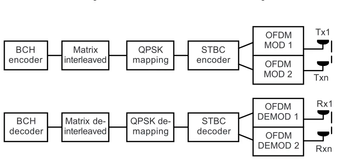
The proposed system employs NT transmit antennas and NR receive antennas as depicted in Figure 1. A stream binary bit of information is generated randomly is assumed equiprobable, then encoded using a BCH channel block coding. The coded binary data then attempt to column-filling and in-row transmitting matrix interleaved in order to span the channel memory effect. Bit to symbol conversion transforms the coded binary data to M elements of modulo-M symbols using Gray mapping prior to mapping into M-ary PSK constellations and then converted into N parallel form. The
l-th block of data is denoted as:
( ) (
)
(
)
{
}
= , +1 ,…, + −1
l
S s lN s lN s lN N (1)
STBC-OD is defined by a (TxNT) transmission matrix G ,
T
N T given by,
=
1,1 1,2 1, 2,1 2,2 2, ,1 ,2 ,
T
T
T
T
N
N N ,T
T T T N
g g g
g g g
g g g
G (2)
where each of elements gi,jis a linear combination of a subset of element of Sland their conjugates, NT is the number of transmission antennas and T is the symbol period of STBC-OD system. In order to utilize the space-frequency diversity, the input blocks for OFDM at each transmit antenna should have the length of N. STBC-OD
Figure 1 Proposed system
BCH encoder
Matrix interleaved
QPSK mapping
STBC encoder
OFDM MOD 1
OFDM MOD 2
OFDM DEMOD 1
OFDM DEMOD 2 STBC
decoder QPSK
de-mapping Matrix
de-interleaved BCH
decoder
Txn
provides NT blocks: S S1′ ′, ,2 …SN′Tof the length N, each consisting of N/T sub-blocks, i.e.,
(
)
−
= ,0 ,1 , 1T, =1, 2,…,
i i i i N i NT
S s s s (3)
where [.]T is matrix transpose. OFDM modulators generate blocks with length N:
…
1, 2, , NT
X X X (4)
that corresponds to Si, where they will be transmitted by first, second, … and NT-th transmit antennas, respectively. Assuming that the guard time interval is longer than the largest delay spread of the multipath channel to avoid intersymbol interference, the received signal will be the convolution of the channel response and the transmitted signal. It is also assumed that the channel is static during one OFDM block. At the j -th receiver antenna, at -the receiver after removing -the cyclic prefix, -the FFT output can be stated as:
=
=
∑
+1
T
N
j ij i j
i
R H S W (5)
where
(
)
−
= 0 1 1T =1 2 …
j rj , rj , rj ,N , j , , ,NR
R (6)
which rj,n is the received signal at the received antenna j at time n. and Hij represents a three-dimensional matrix whose elements:
(
Hi , j ,k, i =1,2,…NT j =1,2,…NR k=0,1,2,…,N−1)
(7) are FFT of the frequency response of the channel hi,j,k and Wj = [W0, …, WN-1]T denotes the AWGN experienced by j-th receive antenna.Assuming that the channel state information is known at the receiver, the maximum-likelihood (ML) algorithm can be used for STBC-OD decoding of the received signal, which is only a linear processing. Using a coherent detection, the receiver decodes the received signals to recover the transmitted symbols. The detected symbol is:
= = =
=
∑∑∑
1 1 1
R T
N N T
k i , j ,Tk t , j ,k j i t
s H r (8)
(
)
(
)
(
)
∈
∈
= −
= − −
A
A
2
min min
k k
s
* *
k k
s
s s s
s s s s (9)
that performed over all symbol s∈A, where A is a set of the constellation components. After symbol to bit conversion, block sk, k = 0, 1, …, N-1, is de-interleaved and then sent to the outer decoder, particularly BCH decoder. Detail elaboration and illustration of STBC-OD that provide transmission of full rate, half rate and three quater rates are presented in the next sub-sections.
2.1 Full Rate of Transmission
Full rate of transmission using STBC-OD only is provided by employing two transmit antennas. The corresponding matrix code for two transmit antennas is G22 [6], which can be written as follows:
∗ ∗
=
+1 22
+1 1 2
=
-k k
k k
,k ,k
s s
s s
s s
G
(10)
where * is complex-conjugate, k = 0,… , . N −1,
T and sub-blocks of s1,k and s2,k are:
∗ ∗
+ +
= − =
1 2 2 1 2 2 1 2
T T
,k s k s k , ,k s k s k
s s (11)
Then two blocks, S1 and S2 of the length N are provided as follows:
− −
= =
2
1 1,0 1,1 1N 1 2 2,0 2,1 2,N 1
2
T T
,
s s s , s s s
S S (12)
Next, OFDM modulator generates blocks X1 and X2 correspond to S1 and S2, that will be transmitted simultaneously by the first and second transmit antennas, respectively. Cyclic prefix symbols with appropriated-length are inserted into the blocks to combat intersymbol interference at the channel.
The received signal at the j-th receive antenna after removing cyclic prefix and OFDM demodulation can be written as follows:
= 1 1+ 2 2+
j j j j
R H S H S W (13)
∗ ∗ =
∗ ∗
+ + +
=
= +
= −
∑
∑
2 1 2 1 2 2 2 1
2 1 2 2 1 1 1 2 1 2 1
R
R
N
k ,j , k ,j ,k ,j , k ,j ,k j
N
k ,j , k ,j ,k ,j , k ,j ,k j
s H r H r
s H r H r (14)
where
+
= =
1,j ,k j , k2 2,j ,k j , k2 1
r r , r r (15)
The above decision variables provide a diversity gain of order two for every s2k and
s2k+1. The recovery received symbols are obtained by using the decision rule in Equation (9). Then, the decoded signals will proceed in outer decoder that is BCH decoder. The simplified decoding algorithm of Equation (14) is presented in detail in Appendix 1.
2.2 Half Rate of Transmission
Half rate transmission can be acquired by employing three or four transmit antennas combined with its correspond matrix code G38 and G48, respectively. Here, we derive the half rate of transmission by employing four transmit antennas, relied on the fact that it is easier to perform than for the three transmit antennas. Furthermore, the results can be generalized for three transmit antennas and using matrix code G38.
Let us consider an STBC-OD for four transmit antennas (NT = 4) using a code G48 [6], given by:
+ + +
+ + +
+ + +
+ + +
∗ ∗ ∗ ∗
+ + +
∗ ∗ ∗ ∗
+ + +
∗ ∗ ∗ ∗
+ + +
∗ ∗ ∗ ∗
+ + +
− −
− −
− − −
=
− −
− −
− −
4 4 1 4 2 4 3 4 1 4 4 3 4 2 4 2 4 3 4 4 1 4 3 4 2 4 1 4
4 4 1 2 4 3 4 1 4 4 3 2
2 4 3 4 4 1 4 3 4 2 4 1 4
k k k k
k k k k
k k k k
k k k k
k k k k
k k k k
k k k k
k k k k
S S S S
S S S S
S S S S
S S S S
S S S S
S S S S
S S S S
S S S S
48
G
(16)
which can be written as:
(
)
= 1, 2, 3, 4, , =0,1, ,… N8 −1
k k k
k k
48 s s s s
where
∗ ∗ ∗ ∗
+ + + + + +
∗ ∗ ∗ ∗
+ + + + + +
∗ ∗ ∗ ∗
+ + + + +
∗ ∗
+ + + + +
= − − − − − −
= − −
= − − − − −
= − −
1, 4 4 1 4 2 4 3 4 4 1 4 2 4 3 2, 4 1 4 4 3 4 2 4 1 4 4 3 4 2
3, 4 2 4 3 4 4 1 4 2 4 3 4 4 1 4, 4 3 4 2 4 1 4 4 3 4 3
T
k k k k k k k k
k
T
k k k k k k k k
k
T
k k k k+ k k k k
k
k k k k k k
k
s s s s s s s s
s s s s s s s s
s s s s s s s s
s s s s s s
s
s
s
s s4∗k+1 4s∗kT
(18)
It can be seen that STBC-OD will send four symbols in eight times symbol resulting in half transmission rate.
Four blocks, Si, i = 1, 2, 3, 4 are provided by matrix code G48 as follows:
( )
−
= ,0 ,1 ,N8 1 , = 1, 2, 3, 4
T
i si si si i
S (19)
OFDM modulator generates four blocks, X1, X2, X3 and X4 related to S1, S2, S3
and S4 that are transmitted through first, second, third and forth antennas respectively. The received signal at the j-th receive antenna after cyclic prefix removing and OFDM demodulation is:
= 1 1+ 2 2+ 3 3+ 4 4+
j j j j j j
R H S H S H S H S W (20)
These received signals from all receive antennas are combined in the combiner and the estimated values of the transmitted symbols are computed as follows:
∗ ∗ ∗ ∗
∗ ∗ ∗ ∗
=
∗ ∗ ∗ ∗
+1
+ + +
=
+ + +
− − −
=
∑
1 8 1, , 2, ,8 2, , 3, ,8 3, , 4, ,8 4, , 41 1 8 5, , 2, ,8 6, , 3, ,8 7, , 4, ,8 8, , 2 8 1, , 1, ,8 2, , 4, ,8 3, , 3, ,8 4
R
N , j, k j k j k j k j k j k j k j k
k
j , j, k j k j k j k j k j k j k j k
, j, k j k j k j k j k j k j k k
H r H r H r H r
s
+H r H r H r H r
H r H r H r H
s ∗ ∗ ∗ ∗
=
∗ ∗ ∗ ∗
+2 ∗ ∗ ∗ ∗
− − −
+ − −
=
+ − −
∑
4, ,1 2 8 5, , 1, ,8 6, , 4, ,8 7, , 3, ,8 8, , 3 8 1, , 4, ,8 2, , 1, ,8 3, , 2, ,8 4, , 4
3 8 5, , 4, ,8 6, , 1, ,8 7, , 2, ,
R
N j k
j , j, k j k j k j k j k j k j k j k
, j, k j k j k j k j k j k j k j k k
, j, k j k j k j k j k j k j
r
+H r H r H r H r
H r H r H r H r
s
+H r H r H r H ∗
=
∗ ∗ ∗ ∗
+3 ∗ ∗ ∗ ∗
=
− + −
=
− + −
∑
∑
1 8 8, ,
4 8 1, , 3, ,8 2, , 2, ,8 3, , 1, ,8 4, , 4
1 4 8 5, , 3, ,8 6, , 2, ,8 7, , 1, ,8 8, ,
R
R
N
j k j k
N , j, k j k j k j k j k j k j k j k
k
j , j, k j k j k j k j k j k j k j k
r
H r H r H r H r
s
+H r H r H r H r
where
+ −
=
, 8 1
i k k i
r r (22)
where k=0,1, ,… N8 −1, i = 1, 2, …, 8. The ML detector assumes that the channel
state information is known at the receiver and uses the decision rule in Equation (9) to recover the transmitted symbols. We also assume that the channel response of eight adjacent subchannels are approximately equal, i.e. H1,8k+q = H1,8k,H2,8k+q = H2,8k, H3,8k+q = H3,8k, for q = 0, 1, …,7.
When transmitter employs three transmit antennas and requires half rate of transmission, the corresponding STBC-OD is G38 [6], which is defined by:
+ + + + + + + + + ∗ ∗ ∗ + + ∗ ∗ ∗ + + ∗ ∗ ∗ + + ∗ ∗ ∗ + + + − − − − − = − − − − −
3 3 1 3 2 3 1 3 3 3 3 2 3 3 3 3 3 3 2 3 1
3 3 1 3 2 3 1 3 3 3 3 2 3 3 3 3 3 3 2 3 1 38
G
k k k
k k k
k k k
k k k
k k k
k k k
k k k
k k k
s s s
s s s
s s s
s s s
s s s
s s s
s s s
s s s
(23)
It is seen that G38 can be obtained from G48 by deleting the right-most column and the results consist of four transmitted symbols which are transmitted in T = 8Ts. Thus, the transmission rate remains half. The impact of deleting the right most column of G48 to obtain G38 are the absence of all forth column elements of G48 in the received signals in Equation (21). We have:
∗ ∗ ∗
∗ ∗ ∗
=
∗ ∗ ∗
+1 ∗ ∗
+ + = + + − + = − +
∑
1 8 1, , 2, ,8 2, , 3, ,8 3, , 31 1 8 5, , 2, ,8 6, , 3, ,8 7, , 2 8 1, , 1, ,8 2, , 3, ,8 4, , 3
2 8 5, , 1, ,8 6, , 3, ,8 8,
R
N
,j, k j k j k j k j k j k k
j ,j, k j k j k j k j k j k
,j, k j k j k j k j k j k k
,j, k j k j k j k j k
H r H r H r
s
+H r H r H r
H r H r H r
s
+H r H r H r∗
=
∗ ∗ ∗
+2 ∗ ∗ ∗
= ∗ ∗ ∗ +3 ∗ − − = + + − + − = − +
∑
∑
1 ,3 8 1, , 1, ,8 3, , 2, ,8 4, , 3
1 3 8 5, , 1, ,8 7, , 2, ,8 8, , 3 8 2, , 2, ,8 3, , 1, ,8 4, , 3
3 8 6, , 2,
R
R
N
j j k
N
,j, k j k j k j k j k j k k
j ,j, k j k j k j k j k j k
,j, k j k j k j k j k j k k
,j, k j k j
H r H r H r
s
+H r H r H r
H r H r H r
s
H r H ∗ ∗
= −
∑
1 ,8 7, , 1, ,8 8, ,
R
N
j kr j k H j kr j k
The simplified version of Equations (21) and (24) are presented in Appendix 1.
2.3 The Three Quarter Rate of Transmission
Multiple transmit antennas system can also provide quarter transmission rate when it employs three or four transmit antennas, and uses its correspond matrix codes G34 and G44, respectively. We follow the description at the previous sub-section to present the explanation of the three quarter transmission rate. It is easier to understand when we start with employing four transmit antennas and then derive the encoding and decoding process for three transmit antennas.
The matrix code G44, which is STBC-OD for four transmit antennas (NT = 4), is defined by [6] as:
(
) (
)
(
)
(
)
+ + +
∗ ∗
+ + +
∗ ∗ ∗ ∗ ∗ ∗
+ + + + + +
∗ ∗ ∗ ∗ ∗ ∗
+ + + + + +
−
=
− − + − − +
− − + − − − + −
1 1
4 4 1 2 4 2 2 4 2
1 1
4 1 4 2 4 2 2 4 2
1 1 1 1
4 2 4 2 4 4 4 1 4 1 4 4 4 1 4 1
2 2 2 2
1 1 1 1
4 2 4 2 4 4 4 1 4 1 4 4 4 1 4 1
2 2 2 2
2 2
2 2
2 2
2 2
k k k k
k k k k
k k k k k k k k k k
k k k k k k k k k k
s s s s
s s s s
s s s s s s s s s + s
s s s s s + s s s s s
G44
(25) which can be written as:
(
)
= 1, 2, 3, 4, , =0,1,…,N4 −1
k k k k k
s s s s
G44 (26)
where
(
) (
)
(
)
∗ ∗ ∗
+ +2 +2
∗ ∗ ∗
+ +2 +2
∗ ∗ ∗ ∗
+2 +2 + + + +
∗ ∗
+2 +2 + +
= −
= −
= − − − − −
= − − − −
1 1
1, 4 4 1 2 4 2 4
1 1
2, 4 1 4 2 4 2 4
1 1 1 1
3, 2 4 2 4 2 4 4 4 1 4 1 2 4 4 4 1 4 1
1 1 1 1
4, 2 4 2 4 2 4 4 4 1 4 1 2 4
2 2
2 2
2 2
2 2
T
k k k k k
T
k k k k k
T
k k k k k k k k k k k
k k k k k k k
s s s s
s s s s
s s s s + s s s s + s s
s s s s + s + s s
s
s
s
s
(
k−s + s4∗k 4k+1−s4∗k+1)
T (27)STBC-OD provides four blocks of Si, i = 1, 2, 3, 4 that will be transmitted through
i-th transmit antenna:
(
)
N 4
i,0 i,1 i, −1 , i 1,2,3, 4
= =
Si s s s T (28)
OFDM modulators generate blocks X1, X2, X3 and X4 correspond to Si at Equation (28) that are transmitted by first, second, third and fourth transmit antenna, respectively.
The received signal at each receive antenna after OFDM demodulation are: rj = H1jS1 + H2jS2 + H3jS3 + H4jS4 + Wj (29) The combiner collects the received signals from all receive antennas and results the estimated values of the transmitted symbols written as:
(
)(
)
(
)(
)
(
)(
)
∗ ∗ ∗ ∗
∗ =
∗ ∗ ∗ ∗
+
+ + − −
=
− + +
− + − +
=
+ +
∑
1
1, ,4 1, , 2, ,4 2, , 2 3, ,4 4, ,4 4, , 3, , 4
1
1 2 3, ,4 4, ,4 3, , 4, , 1
2, ,4 1, , 1, ,4 2, , 2 3, ,4 4, ,4 3, , 4, , 4 1
1
3, ,4 4, , 2
R
N j k j k j k j k j k j k j k j k
k
j j k j k j k j k
j k j k j k j k j k j k j k j k
k
j k j
H r H r H H r r
s
H H r r
H r H r H H r r
s
H H
(
)(
)
(
)
(
)
(
)
(
)
∗ =
∗ ∗
+ ∗ ∗
=
− +
+ + −
=
+ + + −
∑
∑
1 4 3, , 4, ,
3, ,4 1, , 2, , 4, ,4 1, , 2, , 1
4 2 2
1 1, ,4 2, ,4 3, , 1, ,4 2, ,4 4, ,
2
R
R
N
j k j k j k
N j k j k j k j k j k j k
k
j j k j k j k j k j k j k
r r
H r r H r r
s
H H r H H r
(30)
where
ri,k =r4k+i−1 (31) where k=0,1, ,… N4 −1, i= 1, 2, …, 4 and it assumes that the channel state information
is known at the receiver. And we also assume that the channel response of eight adjacent subchannels are approximately equal, i.e. H1,4k+q=H1,4k, H2,4k+q=H2,4k, H3,4k+q=H3,4k, for q= 0, 1, 2, 3. The recovery received symbols are obtained using the decision rule in Equation (9).
We consider using three transmit antennas in obtaining ¾ transmission rate, the corresponding STBC-OD is G34 [6] as shown below:
(
)
(
)
+ +
∗ ∗
+ +
∗ ∗ ∗ ∗
+ + + +
∗ ∗ ∗ ∗
+ + + +
−
=
− − + −
− − + +
1
3 3 1 2 3 2 1
3 1 3 2 3 2
1 1 1
3 2 3 2 3 3 3 1 3 1
2 2 2
1 1 1
3 2 3 2 3 3 3 1 3 1
2 2 2
2 2
2 2
2 2
k k k
k k k
k k k k k k
k k k k k k
s s s
s s s
s s s s s s
s s s s s s
The code above is obtained by deleting the right-most column of matrix code G44 in Equation (25) and we found that there are three symbols transmitted in four symbol periods, Ts. The G44 decoding algorithm in Equation (30) can be performed to decode the G34 by removing all components in the fourth column of G44. The combiner collects the received signals from all receive antennas and results the following estimated value of the transmitted symbols:
(
)
(
)
(
)
(
)
1
1, ,4 1, , 2, ,4 2, , 2 3, ,4 4, , 3, , 3
1
1 2 3, ,4 3, , 4, ,
1
2, ,4 1, , 1, ,4 2, , 2 3, ,4 3, , 4, , 3 1
1
1 3, ,4 3, , 4, , 2
∗ ∗ ∗
∗ =
∗ ∗ ∗
+ ∗
=
+ + −
=
− +
− + +
=
+ − +
∑
∑
R
R
N j k j k j k j k j k j k j k
k
j j k j k j k
N j k j k j k j k j k j k j k
k
j j k j k j k
H r H r H r r
s
H r r
H r H r H r r
s
H r r
(
) (
)
(
)
3, ,4 1, , 2, , 1, ,4 2, ,6 3, , 1
3 2 2
1 1, ,6 2, ,4 4, ,
2
∗ ∗
+ ∗
=
+ + +
=
+ −
∑
NR j k j k j k j k j k j kk
j j k j k j k
H r r H H r
s
H H r
(33)
The simplified equation of decoding algorithm in Equations (30) and (33) is presented in Appendix 1.
3.0 PERFORMANCE ANALYSIS
The BCH encoder receives K information symbols and results the N coded symbols stated as C(N,K). Note that, the length of the coded symbol must be the same with the length of OFDM frame. The union bound for the bit error rate of a linear block code C(N,K) is [11]:
( )
, 0 0
= =
≤
∑ ∑
K Nb k d u
k d
k
P A P d
K (34)
where Ak,d is the number of codewords with input weight k and output weight d,
Pu(d) is the unconditional pairwise error performance (PEP), which is defined as the probability of decoding in favour of a codeword with weight d when the all-zero codeword is transmitted. The weight distribution Ak,d is obtained directly from the weight enumerator of the code [11].
fading blocks. Assume the number of fading blocks with weight v is fv and k = min
(m, d). The pattern f=
{ }
fv vk=0 occurs if fv’s sum up to F, and cumulative weight equals d. Having all the possible patterns, the average of the PEP over the patterns is [12]:( )
( )
( )
1 2
2 1 1 1
= = =
=
∑ ∑ ∑
F F
F
f f f
k
/ /k
u c
d
f f f
E P d P d p (35)
where p(f) is the weight of occurrence of the pattern f.
In the following explanation, we introduce the PEP under equivalent block fading in case of independent antennas. We assume M-ary PSK modulation for the given PEP’s.
For a given channel code C, assuming all-zero codeword is transmitted, the PEP of a codeword with weight d given the pattern f of the fading blocks, is [12]:
( )
,1 1
γ
= =
=
∑ ∑
f
v
f k
c v i
v i
P d Q M v (36)
where γv i, =h R Ev i c b4, /No is the signal to noise ratio (SNR) per information bit of the symbols in the i-th fading block which has the weight v, with associated fading coefficient hv,i and Rc is the code rate. The term Eb states the energy of information bit and No states energy of noise.
In the case of NT transmit and NR receive antennas, the resultant SNR per bit is:
, 1 1
1
γ γ
= =
=
∑∑
NT NR i j T i jN (37)
Recall the Q-function in alternative form in [13] which can be rewritten as:
( )
0 221
exp
2 sin
π ψ
θ
π θ
−
= −
∫
xQ x d (38)
where ψ = π / M. Thus, PEP conditioned on the block fading pattern f is [12]:
( )
( 1 /), 2
0
1 1
1 1
exp sin
π
γ θ
π θ
−
= =
= −
∑ ∑
∫
f
v
f k
M M
c v i
v i
P d v d (39)
Averaging the above PEP over the instantaneous SNRγ, the unconditional PEP is
the fading coefficients affecting a codeword. Since γv,i’s are all independent, the multiple integral reduces to product of integrals,
( )
( 1 /) ,( )
, , 2
0
1 1 0
1
exp sin
π
γ
γ
γ γ θ
π θ
∞ −
= =
= −
∏∏
∫
∫
f
v
f k
M M v i
c v i v i
v i
v
P d p d d (40)
Note that the inner integral is characteristic function of γ, Φ(s) = E(esγ), evaluated at s = -v/sin2θ, hence
( )
( 1 /)2 0
1
1
sin
π
θ
π θ
−
=
= Φ −
∏
∫
f
v
f k
M M
c
v
v
P d d (41)
In the case of independent γi,j’s in (37), the resultant SNR is the sum of NTNR
independent exponential variables and hence has a chi-square distribution with the probability of density function (pdf) is [12]:
( )
(
1)
1exp(
/)
1 !
γ γ = − γDγD− γ γ
p
D (42)
where
1
γ = b
T o
E
M N (43)
is the average of SNR per bit and D = NTNR. The characteristic function of its pdf is given by:
( ) (
)
γ γ −
Φ s = 1−s D (44)
Using characteristic function in Equation (34), we obtain the following unconditioned PEP [12]:
( )
( )(
)
(
)
1 /
2 0
1 1
1
1 sin 1
1 1 /
π γ
θ
π θ
γ
− −
=
− =
= +
≤ +
−
∏
∫
∏
f
v
v
f D k
M M
u
v k
f D
v
v
P d d
v
M M (45)
4.0 SIMULATION RESULTS
We generate equiprobable-binary data randomly and encode using BCH code with a block length of information K = 191 and length of code N = 255. This code provides almost ¾ of rate and capable to recover 8 bits error. The appropriate size of the matrix interleaved that we chose is 17x15 and size of the matrix de-interleaved is 15x17. After the bit to symbol conversion, a Gray mapping and PSK constellation mapping were perform consecutively prior to serial-to-parallel conversion. STBC-OD matrix map the parallel symbols to space-time codes and feed it to OFDM modulators. We use IFFT with N = 128 and then add it with cyclic prefix as guard time with the length of 32 (25% of IFFT length). These OFDM blocks transmitted simultaneously through transmit antennas with the equal power.
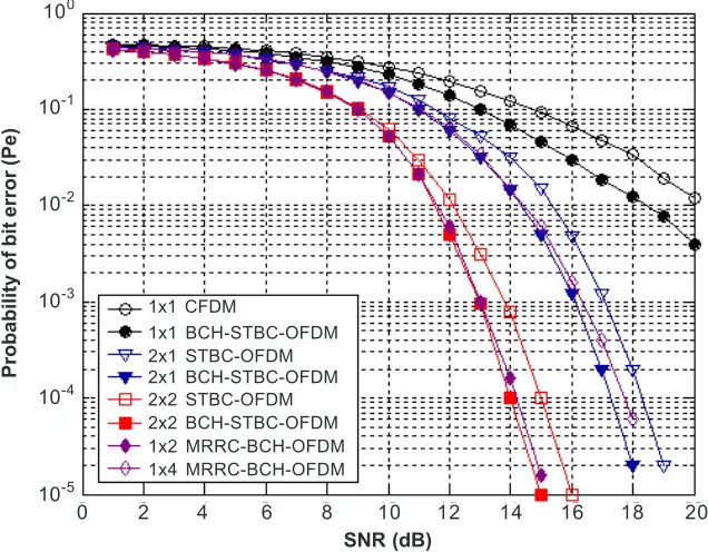
First, we investigate performance of our proposed system by using Alamouti’s scheme [5] that provide full rate of transmission combined with OFDM and compare the results with maximum-ratio receiver combining (MRRC) technique and also with conventional STBC-OFDM (CSTBC-OFDM). The results were shown in Figure 2. When compared to the single transmit antenna system, our proposed scheme has shown significant probability of error, Pe, improvement. At SNR = 14 dB, the proposed system gives probability of bit error Pe = 1.5 × 10⁻² and CSTBC-OFDM experiences probability of bit error Pe = 3.14 × 10⁻². At the same value of probability of bit error
Figure 2 Probability of error performance of the proposed system using G22 compared to MRRC schemes and conventional STBC-OFDM
SNR (dB)
Probability of bit error (Pe)
100
10-2 10-1
10-3
10-4
10-5
2 4 6 8 10 12 14 16 18 20
0
1x4 MRRC-BCH-OFDM 1x2 MRRC-BCH-OFDM 1x1 CFDM
Pe = 10-4, our proposed system has 1 dB advantage in SNR over CSTBC-OFDM. The same results were obtained when the system employed two receive antennas. At SNR = 14 dB, the proposed system reach probability of bit error Pe = 10-4 while CSTBC-OFDM reach probability of bit error Pe = 8 × 10⁻⁴. At probability of bit error Pe = 10-5, the proposed system gives about 1 dB gain over CSTBC-OFDM. Figure 2 also shows that our proposed system performance as good as MRRC technique when employing the same number of antennas.
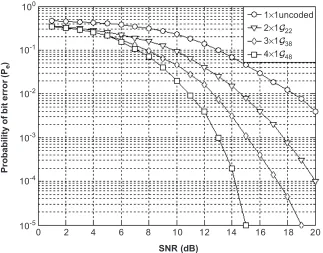
Figure 3 provide simulation results for transmission of 1 bit/sec/Hz using one (uncoded), two, three and four transmit antennas. The transmission using two transmit antennas employs the binary PSK (BPSK) constellation and the code G22. For three and four transmit antennas, the QPSK constellation and the codes G38 and G48, respectively, are used. Since G38 and G48 are half rate codes, again the total transmission rate in each case is 1 bit/sec/Hz. It is shown that at the probability of bit error
Pe = 10-4, the half rate QPSK G48 gives about 3 dB gain over the half rate QPSK G38 and gives about 6 dB gain over the full rate BPSK G22 code.
Figure 3 Probability of bit error versus SNR for BCH/STBC-OD/FDM systems at 1 bit/sec/Hz, one receive antenna
1×1uncoded 2×1G22
3×1G38
4×1G48
100
Probability of bit error (P
e
)
10-1
10-2
10-3
10-4
10-5
0 2 4 6 8 10 12 14 16 18 20
SNR (dB)
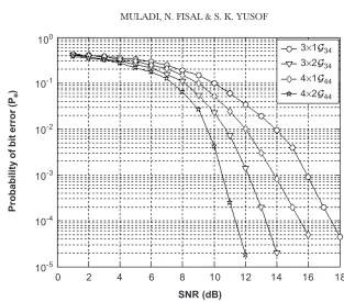
4, it is seen that at the probability of bit error Pe = 10-4 the ¾ rate QPSK and G44 gives about 2 dB gain over the use of QPSK and G34 using single receive antenna. The same gain value is also obtained when using two receive antennas.
The above simulations demonstrate that concatenated BCH with STBC-OD in OFDM system can achieve significant gains by increasing the number of transmit antennas.
5.0 CONCLUSION AND FUTURE RESEARCH
We have proposed serially concatenated BCH code with STBC-OD in OFDM systems employing multiple transmit and receive antennas. Our proposed system gives significant gain over CSTBC-OFDM systems both by using multiple transmit antennas or multiple receive antennas. The proposed system gives the same performance as MRRC technique using equal number of antennas. Significant gain was also provided when increasing the number of transmit antennas chains with very little decoding complexity. The simulations results demonstrate that significant gain can be achieved by increasing the number of receive antennas. In the fast-vary channel, any channel estimator schemes cannot estimate the channel state information accurately. Further research is required to investigate the effect of the imperfect channel estimation to the system performance. In future, we will consider the use the unitary space-time coding Figure 4 Probability of bit error versus SNR for BCH/STBC-OD/OFDM systems at 1.5 bit/sec/Hz using one and two receive antennas
0
SNR (dB)
100
Probability of bit error (P
e
) 10 -1
10-2
10-3
10-4
10-5
2 4 6 8 10 12 14 16 18
3×1G34
3×2G34
4×1G44
and differential space-time block coding that do not require channel state information in the decoding processes. Product turbo code with block codes as its element codes is another alternative code to be investigated in STBC-OD OFDM transmission systems.
REFERENCES
[1] Stirling-Gallacher, R. A., and Z. Wang. 2001. Improving Performance of Coherent Coded OFDM Systems Using Space-Time Transmit Diversity. IEEE Electronic Letters. 37(7): 457-458.
[2] Li, Y. (Geoffrey), J. C. Chuang, and N. R. Sollenberger. 1999. Transmitter Diversity for OFDM Systems and its Impact on High-Rate Data Wireless Networks. IEEE Journal on Selected Areas in Communications. 17(7): 1233-1243.
[3] Gesbert, D., M. Shafi, S. Da-shan, P. J. Smith, and A. Naguib. 2003. From Theory to Practice: An Overview of MIMO Space-Time Coded Wireless Systems. IEEE Journal on Selected Areas in Communications. 21(3): 281-302.
[4] Tarokh, V., N. Seshadri, and A. R. Calderbank. 1998. Space-Time Codes for High Data Rate Wireless Communications: Performance Criterion and Code Construction. IEEE Transactions on Information Theory. 44(2): 744-765.
[5] Alamouti. S. M. 1998. A Simple Transmit Diversity Technique for Wireless Communication. IEEE Journal on Selected Areas in Communications. 16(8): 1451-1458.
[6] Tarokh, V., H. Jafarkhani, and A. R. Calderbank. 1999. Space-Time Block Codes from Orthogonal Designs.
IEEE Trans. on Information Theory. 45(5): 1456-1467.
[7] Tarokh, V., H. Jafarkhani, and A. R. Calderbank. 1999. Space-Time Block Coding for Wireless Communications: Performance Results. IEEE Journal on Selected Areas in Communications. 17(3): 451-459. [8] Naguib, A. F., V. Tarokh, N. Seshadri, and A. R. Calderbank. 1998. A Space-Time Coding Modem for High-Data-Rate Wireless Communications. IEEE Journal on Selected Areas in Communications. 16(8): 1459-1478.
[9] 3rd Generation Partnership Project 3G TS25.212. 1999. Multiplexing and Channel Coding (FDD). 3GPP Technical Specification Group Radio Access Network. Released 1999. version 3.5.0 (2000-12).
[10] Proakis, J. G. 2000. Digital Communications, New York: McGraw-Hill. 14: 878-885.
[11] Benedetto, S., D. Divsalar, G. Montorsi, and F. Pollara. 1998. Serial Concatenatenation of Interleaved Codes: Performance Analysis, Design, and Iterative Decoding. IEEE Transactions on Information Theory. 44(3): 909-926.
[12] Simon, M. K., and D. Divsalar. 1998. Some New Twists to Problems Involving the Gaussian Probability Integral. IEEE Transactions on Communications. 46(2): 200-210.
APPENDIX
In this appendix, we provide the simplified ML decoding algorithm in Equations (12), (17), (20), (24) and (27).
By substituting Equations (11) and (13) into Equation (12), the decoding algorithm of Equation (12) would be:
(
)
{
}
(
)
{
}
∗ ∗ + = ∗ ∗ + + + = = + + + = + + −∑
∑
2 22 1, ,2 2 , ,2 1, ,2 ,2 2, ,2 ,2 1 1
2 2
2 1 1, ,2 2 , ,2 2, 1 2 , ,2 1, ,2 1, ,2 ,2 1 1
R
R
N
k j k j k k j k j k j k j k
j N
k j k j k k j k j k j k j k
j
s H H s H W H W
s H H s H W H W
(46)
Substituting Equations (16) and (18) into Equation (17), we obtain the simplified form of Equation (17):
∗ ∗ ∗ + + = = ∗ ∗ ∗ ∗ ∗ + + + + + = + + + + = + + + + + =
∑
∑
∑
4 2, ,8 4 1, ,8 ,8 2, ,8 ,8 1 3, ,8 ,8 2 1
4 1
4, ,8 ,8 3 1, ,8 ,8 4 2, ,8 ,8 5 3, ,8 ,8 6 4, ,8 ,8 7 4 2 , ,8 1 4 1 2 2 R
N i j k k j k j k j k j k j k j k
i k
j
j k j k j k j k j k j k j k j k j k j k
i j k i
k
H s H W H W H W
s
H W H W H W H W H W
H s ∗ ∗ ∗ + + + = ∗ ∗ ∗ ∗ ∗ + + + + + ∗ + = + + − − − + − − − + + =
∑
∑
4 1 2, ,8 ,8 1, ,8 ,8 1 4, ,8 ,8 2 1
3, ,8 ,8 3 2, ,8 ,8 4 1, ,8 ,8 5 4, ,8 ,8 6 3, ,8 ,8 7 4
2
, ,8 4 2 3, ,8 ,8 1
4 2
2
R
N k j k j k j k j k j k j k
j
j k j k j k j k j k j k j k j k j k j k
i j k k j k j k
i k
s H W H W H W
H W H W H W H W H W
H s H W H
s ∗ ∗ + + = ∗ ∗ ∗ ∗ ∗ + + + + + ∗ ∗ + + = + − − + + − − + − + =
∑
∑
4, ,8 ,8 1 1, ,8 ,8 2 1
2, ,8 ,8 3 3, ,8 ,8 4 4, ,8 ,8 5 1, ,8 ,8 6 2, ,8 ,8 7 4
2
, ,8 4 3 4, ,8 ,8 3, ,8 ,8 1 2, ,8 1
4 3
2
R
N j k j k j k j k
j
j k j k j k j k j k j k j k j k j k j k
i j k k j k j k j k j k j k
i k
W H W
H W H W H W H W H W
H s H W H W H
s ∗ + = ∗ ∗ ∗ ∗ ∗ + + + + + − + − + −
∑
,8 21
1, ,8 ,8 3 4, ,8 ,8 4 3, ,8 ,8 5 2, ,8 ,8 6 1, ,8 ,8 7
R
N j k
j
j k j k j k j k j k j k j k j k j k j k
W
H W H W H W H W H W
Using the same way, we obtain the simplified presentation of Equation (20) as:
3
2
, ,8 3 1, ,8 ,8 2, ,8 ,8 1 1
3 1
3, ,8 ,8 2 1, ,8 ,8 4 2, ,8 ,8 5 3, ,8 ,8 6 3
2
, ,8 3 1 2, ,8 ,8 1, ,8 , 1 3 1 2 2 ∗ ∗ + = = ∗ ∗ ∗ ∗ + + + + ∗ ∗ + = + + + = + + + + + − =
∑
∑
∑
R Ni j k k j k j k j k j k
i k
j
j k j k j k j k j k j k j k j k
i j k k j k j k j k j
i k
H s H W H W
s
H W H W H W H W
H s H W H W
s 8 1
1
3, ,8 ,8 3 2, ,8 ,8 4 1, ,8 ,8 5 3, ,8 ,8 7 3
2
, ,8 3 2 3, ,8 ,8 1, ,8 ,8 2 1
3 2
2, ,8 ,8 3 3, ,8 ,8 4 1, ,8 ,8 6
2 + = ∗ ∗ ∗ ∗ + + + + ∗ ∗ + + = + ∗ ∗ ∗ + + + + + − + + − = − + − −
∑
∑
R N k jj k j k j k j k j k j k j k j k
i j k k j k j k j k j k
i k
j k j k j k j k j k j k
H W H W H W H W
H s H W H W
s
H W H W H W H
1
2, ,8 ,8 7 3
2
, ,8 3 3 3, ,8 ,8 2, ,8 ,8 2 1
3 3 1
1, ,8 ,8 3 3, ,8 ,8 5 2, ,8 ,8 6 1, ,8 ,8 7
2 = ∗ + ∗ ∗ + + = + = ∗ ∗ ∗ ∗ + + + + − + = − − + −
∑
∑
∑
R R N jj k j k
N i j k k j k j k j k j k
i k
j
j k j k j k j k j k j k j k j k
W
H s H W H W
s
H W H W H W H W
(48)
(
)(
)
(
)(
)
∗ ∗ + = = ∗ ∗ + + = ∗ + + = = + + + + = + − − − + + + =∑
∑
∑
∑
2 42 1 2
, ,4 2 , ,4 4 1, ,4 , 2, ,4 ,4 1
1 3
1
4 2 3, ,4 4, ,4 ,4 3 ,4 2 1
1
3, ,4 4, ,4 ,4 2 ,4 3 2
2
2 1 2 1, ,4 2 , ,4 1
4 1
2
2
R
i j k i j k k j k j k j k j k
i i
N
k j k j k j k j k
j
j k j k j k j k
j k i j k
i i
k
H H s H W H W
s H H W W
H H W W
H H
s
(
)(
)
(
)(
)
∗ ∗ + + ∗ ∗ + + = + + + − + − + − + − ∑
∑
44 1 2, ,4 , 1, ,4 ,4 1 3
1
3, ,4 4, ,4 ,4 2 ,4 3 2
1 1
3, ,4 4, ,4 ,4 3 ,4 3 2
R
k j k j k j k j k
N
j k j k j k j k
j
j k j k j k j k
s H W H W
H H W W
H H W W
(
)
∗ ∗ + + = + + + = +∑
4 2 11, ,4 4 2 2 3, ,4 ,4 ,4 1 1
1 4 2 2 4,
2
2
j k k j k j k j k
i
k j
H s H W W
s H
(
) (
)
(
)
∗ ∗ + + = ∗ + − + + + − ∑
1,4 ,4 ,4 1 2 1, ,4 2, ,4 ,4 2 1
1
1, ,4 2, ,4 ,4 3 2
R
N
k j k j k j k j k j k
j
j k j k j k
W W H H W
H H W
The similar result was obtained for Equation (27) simplification as:
(
)
(
)
∗ ∗ + = = ∗ + + + + ∗ + = + + + + = + − − + + + − = ∑
∑
∑
22 1 2
, ,4 2 3, ,4 3 1, ,4 , 2, ,4 ,4 1 1
3
1 1 1
3, ,4 ,4 3 ,4 2 3, ,4 ,4 2 ,4 3
2 2
2
2 1 2
, ,4 2 3, ,4 3 1 2, ,4 ,4 1, , 1
3 1
R
N i j k k j k j k j k j k
j k i
k j
j k j k j k j k j k j k
i j k j k k j k j k j
i k
H H s H W H W
s
H W W H W W
H H s H W H
s
(
)
(
)
(
)
(
)
(
)
∗ + = ∗ + + + + ∗ ∗ + + = + ∗ ∗ + + + + + − + + + + = + + −∑
∑
4 ,4 1
1 1 1
3, ,4 ,4 2 ,4 3 3, ,4 ,4 2 ,4 3
2 2
2
2 2
, ,4 3, ,4 3 2 3, ,4 ,4 ,4 1
1 1
3 2 2
1, ,4 2, ,4 ,4 2 1, ,4 2, ,4 ,4 3
2 2
R
N k j k
j
j k j k j k j k j k j k
i j k j k k j k j k j k
i k
j k j k j k j k j k j k
W
H W W H W W
H H s H W W
s
H H W H H W