20th International Conference on Structural Mechanics in Reactor Technology (SMiRT 20) Espoo, Finland, August 9-14, 2009 SMiRT 20-Division 3, Paper 2459
Application of CFD Code PHOENICS for Simulating CYCLONE
SEPARATORS
Anu Dutta, B. Gera, Pavan K. Sharma
+, R.K.Singh, A. K. Ghosh and H.S. Kushwaha
Reactor Safety Division, Health Safety and Environment Group,Bhabha Atomic Research Centre Trombay, Mumbai, India- 400085, +Email: [email protected]
Keywords: Separator, CFD, IPSA, PHOENICS, Two-phase flow
1
ABSTRACT
Cyclone separators are widely used in the field of air pollution control, gas–solid separation for aerosol sampling and in many industries like power plants, sand plants etc. In cyclone separators the air flow enters the cyclone through a tangential inlet, generates a swirling flow that forces entrained particles radially outward and leaves via an axial outlet pipe at the top of the cyclone. The rotational fluid motion is generated from the energy obtained from the fluid pressure gradient. This rotational motion causes the particle to separate relatively fast due to the strong acting forces. The cyclone separator is very useful engineering equipment with no moving parts and virtually requires no maintenance. It enables particles of micrometers in size to be separated from a gas moving at about 15 m/s without excessive pressure-drop.
This work presents a computational fluid dynamics (CFD) calculation to investigate the flow field in a tangential inlet cyclone which is mainly used for the separation of the moisture from an air stream. Three-dimensional, steady state Eulerian simulations of the turbulent gas–droplet flow in a cyclone separator have been performed. Numerical simulation was carried out using CFD code PHOENICS for the given geometry of separators available in literature. The IPSA (Inter-Phase-Slip Algorithm) method has been utilized which entails solving the full Navier-Stokes equations for each phase. The turbulence was modelled with standard k- turbulence model. The liquid droplet was modelled as particle of size 200 and density 1020kg/m3. The volume fraction of moisture was 5% at inlet and outlet volume fraction was predicted with CFD. This knowledge can be further extended for other two phase flow applications in nuclear industry.
2
INTRODUCTION
The cyclone separator is one of the most elegant devices with no moving parts. It enables particles of micrometers in size to be separated from a gas moving at about 15 m/s without excessive pressure-drop. Cyclone separators are very widely used throughout industry. Moreover, they can be found in all sizes and shapes. They can be used in some industries such as: Power generation, Oil and gas, Incineration plants, Iron and steel industry, Sand plants, Cement plants, Coking plants, Coal fired boilers, Food industries.
Cyclone separator works on the principle of separation of materials in a fluid flow using centrifugal forces. A cyclone separator system yields fast separation and utilizes less space. Separation occurs quickly as the acting centrifugal force is much higher than the gravitational force as compared to normal settling procedure where only gravitational force is acting. It can be used for separation of solid particles or liquids, i.e. droplets, from a fluid stream. In cyclone separators the air flow enters the cyclone through a tangential inlet, generates a swirling flow that forces entrained particles radially outward and leaves via an axial outlet pipe at the top of the cyclone. The rotational fluid motion is generated from the energy obtained from the fluid pressure gradient. This rotational motion causes the particle to separate relatively fast due to the strong acting forces.
Several numerical investigations have been carried out for flow inside a cyclone separator. Minier et al. [1991] used a 3-dimensional Eulerian-Lagrangian approach on a 3-dimensional numerical grid with a modified turbulence model. These authors used a Lagrangian model for the prediction of the particulate phase. Variations of the coefficients of restitution in the particle-wall model from elastic to completely inelastic bouncing behavior have shown only minor influence on the predicted efficiency grade.
Boysan et al. [1982] presented the theory of a 3-dimensional modified algebraic Reynolds stress turbulence model (ASM). They found good agreement between the predicted flow field in the investigated cyclone in the range of the potential vortex and an at least qualitative agreement in the core region. Gorton-H¨ulgerth [1999] performed 3-dimensional calculations for a series of standard cyclones using the commercial computer package FLUENT 4.4.7 and FLUENT UNS 4.2.10 with the built-in RSM turbulence model on a numerical grid with 170,000 cells. Several different cyclone geometries (e.g. variation of the hopper entrance geometry) have been investigated. Numerical results for the gas velocity field show very good agreement with the LDA measurements. A numerical prediction of a flow in a hydro cyclone has been presented in Gesellschaft [1996] using the commercial computer package CFX-5 with two different build-in Reynolds Stress Model (RSM); the Launder, Reece, Rodi closure model (LRR) and the quadratic Speziale, Sarko and Gatski closure model (SSG). Calculations were carried out on a 3-dimensional hexahedral mesh generated with ICEM/CFD-HEXA with approximately 151,000 grid cells. Best agreement with experimental data was achieved with the SSG formulation of the RSM turbulence model. The application of a 3-dimensional LES model has been shown within the frame of the LABFLOW code developed by Shell, Netherlands for the numerical prediction of gas-particle flows in cyclone systems Gesellschaft [1999]. LABFLOW was based on the Lattice- Boltzmann method. The comparison between the measurements and numerical calculations of time averaged tangential velocities at two vertical positions in the cyclone were in excellent agreement.
Derksen [2002] presented a numerical prediction of a flow in a Stair and high-efficiency cyclone at Re = 280,000. He performed the calculations by using a Large-Eddy Simulation model. His results agree well with experimental data (LDA measurements of the average and RMS values of the tangential and axial velocity). Souza et al. [2002] have used sub-grid scale modeling, which characterizes Large-Eddy Simulations (LES) to predict the behavior of a water-fed hydro cyclone. The numerical results captured the main features of the flow pattern and agreed reasonably well with experiments. The authors suggested that LES represents an interesting alternative to classical turbulence models when applied to the numerical solution of fluid flows within hydro cyclones. Huang et al. [2002] developed a partitioning parallel procedure to numerically simulate the fluid flow in complex 3 dimensional domains. They used the developed algorithm to simulate the 3 dimensional turbulent swirling gas flows in cyclone separators. The authors concluded that the developed algorithm could well remove the limitation of speed and capacity of personal computers on a large scale. A numerical model for the analysis of the fluid flow and particle separation has been presented by Ingham and Ma [2002]. Generalized performance correlations for the pressure coefficient and the total collection efficiency to dimensionless geometric and operational parameters have been developed by Pant et al. [2002]. The authors deduced their correlations based on the results of the numerical computations. The influence of agglomeration on the particle separation has been studied by Ho and Sommerfeld [2003]. The authors stated that the separation efficiency increases for small particles.
distribution. However, some discrepancies still exist between the simulation results and experimental ones Wang and Liu [2003]. Wu et al. [2003] have used RSM to simulate the cyclone flow. Their results showed that stagnation and reverse flow in axial direction near the cyclone centre exists. In addition, the tangential velocity increased with the decrease of the finder tube diameter. From the point of view of the influence of turbulence structure, Xiaodong et al. [2003] presented an elementary numerical analysis of the interaction between a particle and a gas phase. The effects of turbulence structure and the thickness of the boundary layer on the separation efficiency in a cyclone separator have been investigated. The results indicate that the separation efficiency decreases with an increase in turbulence intensity and increases with a decrease in the thickness of the boundary layer Xiaodong et al. [2003].
Detached Stress Model (DSM) provided by CFX5.5 was adopted to predict the gas flow field in the cyclone Chao et al [2004]. The authors stated that the DSM model could precisely predict the flow field inside the cyclone separator. Hu et al. [2004] have simulated the three-dimensional strongly swirling turbulent flow in a cyclone separator with a volute inlet to optimize the design by improving the pressure strain generation and convection terms of the Reynolds stress equation in FLUENT 6.0. They obtained good agreement between the predictions and experiments in the separation space and the dust hopper. In the vortex finder the agreement between predictions and measurements is poor, indicating that the turbulence model still needs further improvement. An Eulerian-Lagrangian numerical method is used to simulate the cyclone separator by Snider et al. [2004]. The three-dimensional transient simulations showed excellent agreement with measured data. The authors stated that the CFD analysis reveals details that cannot be experimentally measured, such as internal particle size segregation, wall effects, vortex entrainment, particle-to-particle interactions and agglomeration.
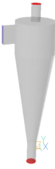
Figure 1. 3D view of the geometry used for computation
predicted from the results of the particle tracing. It was found that the LES has sufficient accuracy to predict the complicated swirling flows in the cyclone separator.
In the present work flow and particle movement inside a cyclone type separator has been studied using CFD code PHOENICS developed by CHAM [25].The cyclone geometry modelled is outlined in Figure 1 below. It consists of a cylindrical part, with a tangential inlet and lower part with an exit at the apex. It operates on the principal that centrifugal forces in the swirling flow separate particles from fluid; thus, the continuous phase leaves by central pipe in the top, while separated particles leave the apex. A 58 x 100 x 75 Cartesian grid is used to divide the calculation domain into 400,000 computational cells. Figure 2 displays the surface grid in an isometric view. At the inlet, a uniform velocity profile was applied ranging from 15-25 m/s and the level of turbulent intensity was set at 5%. The standard k- turbulence model with standard wall function was used for modelling turbulence. This turbulence model has been modified for two phase flow computation and is inbuilt in PHOENICS.
The moisture particles have a mean particle diameter in the order of 200 m. The numerical computations have been carried out assuming uniform particle diameter for all the particles. A particle density of 1020 kg/m3 was assumed. At the inlet 5% volume fraction condition was provided. Series of separation rates were performed for three inlet gas velocity based on Reynolds number.
3
MATHEMATICAL MODEL
Inter-Phase-Slip Algorithm (IPSA) of PHOENICS which solves the full averaged Navier-Stokes equations for each phase was used for the present CFD analysis. The IPSA has been used in PHOENICS to predict thermal and hydrodynamic characteristics of multiphase flows. Calculations were performed on the basis of two-fluid model. The full Reynolds equations of motion for turbulent flow are written for each phase. For steady incompressible flow these equations are:
div
( )
!
Ui =0 (1)div
(
#
UiUj +"
ij)
=!gradP (2)Where Ui is the mean velocity vector, P the mean pressure and the usual stress tensor given by:
' '
3
2
j i ij j i i j j iij
u
u
x
U
x
U
x
U
!
"
#
#
#
#
#
#
µ
$
%
%
+
&
'
(
(
)
*
+
+
+
=
(3)The Reynolds stress tensor is modeled with the aid of a turbulent eddy viscosity. Thus:
ij i j j i t j i
k
x
U
x
U
u
u
!
"
"
"
"
#
µ
3
2
' '$
%
%
&
'
(
(
)
*
+
=
(4)Where k and t are the turbulent kinetic energy and the turbulent viscosity respectively. The turbulent
viscosity is expressed differently depending on the turbulence model used. For example, in the present k- model it is given by:
!
"
µ
µ 2k
C
t
=
(5)and is the kinetic energy isotropic rate of dissipation.
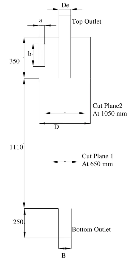
Figure 2. Dimensional Details (All Dimensions are in mm)
4
RESULTS AND DISCUSSION
CFD Analysis has been carried out for the given geometry of cyclone separator at three Reynolds numbers 70000,100000,140000. The results were obtained in terms of velocity distribution and solid particle distribution inside the cyclone separator. Swirling flow inside the separator has been captured and shown in the figure 3. This figure shows the velocity vector at various planes along the separator height at Re=140000. The solid particle distribution inside the separator is shown in figure 4 at Re=140000. This study was restricted to the most common type of cyclone separator where the flow enters the cyclone through a tangential inlet and leaves it via an axial outlet at the top and bottom of the cyclone. The main characteristics of the flow were an annular outer flow which was swirling down the cyclone and an inner core which was moving simultaneously upwards and downward towards the outlet.
The geometry of cyclone separator is basically characterized by the geometrical swirl number Sg = •De •D/ (4 • a • b). Where De is the outlet pipe diameter, D is the cyclone diameter, a is the cyclone inlet duct width, b is the cyclone inlet duct height. All these dimensions are shown in Figure 2. In the present work we have used dimension as Cyclone diameter (D) = 440 mm, Outlet pipe diameter (De) = 100 mm, Cyclone outlet pipe length (S) = 530 mm, Height of the cylindrical section of cyclone (h) = 360 mm, Cyclone height (H) = 1460 mm, Cyclone inlet duct width (a) = 50 mm, Cyclone inlet duct height (b) = 200 mm, Cyclone lower outlet diameter (B) = 110 mm. All these dimensions correspond to Geometrical swirl number (Sg) equal to 3.5.
350
1110
250
D
B De
a
b
Cut Plane 1 At 650 mm
Cut Plane2 At 1050 mm
Cone Inlet Duct
Top Outlet
Due to the complex geometry of the cyclone a solid geometry of the cyclone was developed by building different blocks in PHOENICS. Then this geometry was discretised in Cartesian grids. The mesh density distribution was different in different section of cyclone. In this complex flow field with large gradients a higher cell density in order to capture the correct flow field was provided. Grid was made fine at the inlet and to the region in the vicinity of the lower end of the gas exit tube.
Dirchlit boundary conditions were used at the inlet, which means that the values of the variables are specified. The Reynolds numbers were about 70,000, 100,000 and 140,000 at the inlet duct based on the hydraulic diameter and the bulk velocity. At the inlet area, a uniform plug velocity profile was assumed. The variables that have been specified at the inlet were the normal velocity and the turbulence quantities i.e. turbulence intensity and length scale. The turbulence intensity was defined as 5% and turbulence length scale was provided as 10% of characteristic length.
-0.6 -0.4 -0.2 0.0 0.2 0.4 0.6 -4 -3 -2 -1 0 1 2 3 4
Tangential Velocity m/s
Dimensional Radius -0.6 -0.4 -0.2 0.0 0.2 0.4 0.6
-4.0 -3.5 -3.0 -2.5 -2.0 -1.5 -1.0 -0.5 0.0 0.5
Axial Velocity m/s
Dimensional Radius
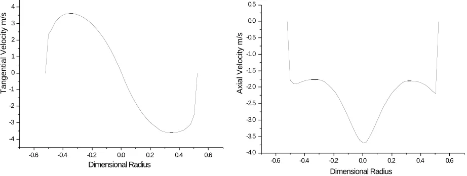
Figure 3. (a)Tangential Velocity at cut plane 1 (b) Axial Velocity at cut plane 1
The results are presented in terms of calculated axial and tangential velocity profiles at different horizontal cut planes in dimensionless form. The spatial position is scaled by the cyclone radius D/2. In Figure 3 (a) the predicted tangential velocity profiles of the continuous phase flow of cut plane 1 are shown. The measured profiles show that the central region in the cyclone rotates like a solid body where the tangential velocity is increasing with an increasing radius. The maximum tangential velocity is reached at a radius 50% from the centre of the cyclone. Then, the tangential velocity starts to decrease and reaches zero velocity at the wall. In Figure 3(b) the predicted axial velocity profiles are shown at cut plane 1. Zero on the radial axis characterizes the centre of the cyclone. There is an outer region close to the wall of the cyclone where the flow is directed downwards with minimum downward velocity. The maximum axial velocity is in the centre of the cyclone where the flow is directed downwards.
-1.0 -0.8 -0.6 -0.4 -0.2 0.0 0.2 0.4 0.6 0.8 1.0 -8 -6 -4 -2 0 2 4 6 8
Tangential Velocity m/s
Dimensionless Radius -1.0 -0.8 -0.6 -0.4 -0.2 0.0 0.2 0.4 0.6 0.8 1.0
-3.0 -2.5 -2.0 -1.5 -1.0 -0.5 0.0 0.5
Axial Velocity m/s
Dimensionless Radius
Figure 4. (a) Tangential Velocity at cut plane 2 (b) Axial Velocity at cut plane 2
very close to the wall. In Figure 4(b) the predicted axial velocity profiles of cut plane 2 are shown. Also here the positive velocities are directed upward towards the outlet.
Figure 5 shows that the static pressure decreases radially from wall to centre and the minimum values appear in forced vortex (solid body rotation). The pressure gradient is the largest along radial direction since there exists a highly intensified forced vortex. The pressure drop between the inlet and outlet has been predicted from the results obtained with CFD computation. These computations have been carried out for various gas inlet velocities. Figure 6(a) shows the obtained total pressure drop as a function of Reynolds Number. This shows that pressure drop increases at high Reynolds number. Figure 6(b) shows the outlet mole fraction at the top outlet. Separation effect increases as Reynolds number increases since high inlet velocity produces high swirl which causes high pressure drop but more particle separation.
Figure 5. Pressure contour at centre Plane at Re=140000
60000 80000 100000 120000 140000 5000
10000 15000 20000 25000 30000 35000 40000 45000
Pressure Drop Pa
Reynolds Number
60000 80000 100000 120000 140000 0
1 2 3 4 5
Mole Fraction %
Reynolds Number
Figure7. (a) Velocity vectors along the separator height at Re=140000 (b) Volume Fraction distribution of solid particle in the separator at Re=140000
Figure 7(a) shows the velocity vectors at different horizontal planes along the height for a clear picture of the velocity field inside the cyclone separator. Figure 7(b) shows the distribution of moisture particles inside the separator. This picture gives the detailed 3D view of the particle distribution.
5
CONCLUSION
The CFD computation of separation of particle by cyclone separator has been carried out for a given geometry of cyclone having geometrical swirl number (Sg) =3.5. The process has been investigated for Reynolds number 70,000,100,000 and 140,000. Results have been obtained with k- turbulence models. The nature of the gas flow of a particle cyclone separator is highly swirling with anisotropic turbulence. Therefore, advanced turbulence models such as RSM or LES have to be applied to predict the gas flow behaviour rather than the meanwhile classical k – turbulence model. The reason for the poor performance of the k model is that the important assumption of isotropic turbulence does not hold in flows with non-uniform pressure distributions such as swirling flows. Depending on a different inlet velocity, the pressure drop and outlet mole fraction at different Reynolds number has been compared. The dynamic behavior of the flow has been captured, providing important information on the flow structure within the cyclone. Also, results of the continuous phase flow formed the basis for modelling solid particle motion in the cyclone based on one-way coupling between the gas flow field and the disperse phase. The pressure drop inside the cyclone has been studied using a fine grid at various gas inlet velocities. With these results, the potential of the current CFD model to simulate flows in a cyclone separator has been distinctly demonstrated. Moreover, numerical investigation of the separation area between the cone and the hopper could be carried out by using Direct Numerical Simulation (DNS).
Minier, J.P., Simonin, O. and Gabillard, M. 1991. Numerical modelling of cyclone separators. Proceedings of the International Conference on Fluidized Bed Combustion, Quebec, Canada, April, 3:1251–1259.
Boysan, F., Ayers, W.H. and Swithenbank, J. 1982. A fundamental mathematical modelling approach to cyclone design. Trans Inst Chem Eng, V 60(N 4):222– 230.
Gorton-H¨ulgerth, A. 1999. Measurement and calculation of velocity fields and Particle in cyclone. PhD thesis, Technical University of Graz, Austria.
Gesellschaft Energietechnik. 1996. Cyclone in the energy and technology. October 29-30 VDI-Berichte 1290, VDI-Verlag, D usseldorf
Gesellschaft Energietechnik. 1999. Cyclone in the energy and technology. October 27-28 VDI-Berichte 1511, VDIVerlag, D usseldorf.
Derksen, J. 2002. LES - based separation performance predictions of a stairmand cyclone. 10th Workshop on Two - Phase Flow Predictions, Martin - Luther Universit¨at Halle - Wittenberg, Halle (Saale), Germany, pages 217–226.
Souza, F. and Neto, A. 2002. Large eddy simulations of a hydro cyclone. In Proceedings of FEDSM ASME Fluid Engineering Division Summer Meeting, Montreal, pages 1 – 6, Quebec, Canada.
Huang, R.G., Huan, B.W. and Zhang, S.P. 2002. Partitioning parallel procedure for numerical simulation of gas flow in a cyclone separator. Journal of Hydrodynamics, 14(1):52–58.
Ingham, D.B. and Ma, L. 2002. Predicting the performance of air cyclones. International Journal of Energy Research, 26(7):633–652.
Pant, K., Crowe, C.T. and Irving, P. 2002. On the design of miniature cyclones for the collection of bio aerosols. Powder Technology, 125(2-3):260–265.
Ho, C.A. and Sommerfeld, M. 2003. Numerical study on the effect of agglomeration for the particle separation in a gas cyclone. In Proceedings of the ASME/JSME Joint Fluids Engineering Conference, volume 1 B, pages 1315–1317.
Lu, T., Qiu, L., Wang, S. and Zhao, D. 2003. The computer simulation - design and application for the double-stage separating cyclone separator. In Energy and the Environment - Proceedings of the International Conference on Energy and the Environment, Halkidiki, Greece, volume 2, pages 1775–1779.
Matsuzaki, K., Munekata, M. and Ohba, H. 2003. Direct numerical simulation of gas-particle turbulent swirling flows in an axially rotating pipe. In Proceedings of the ASME/JSME Joint Fluids Engineering Conference, volume 2 B, pages 1379–1384.
Portela, L.M. and Olieman, R.V.A. 2003. Eulerian-Lagrangian DNS/LES of particle turbulence interactions in wall-bounded flows. International Journal for Numerical Methods in Fluids, 43(9):1045–1065.
Suguri, A., Toda, K. and Yamamoto, M. 2003. Numerical investigation on small scale cyclone for spm removal. Proceedings of the ASME/JSME Joint Fluids Engineering Conference, 1 B: 805–810.
Wang, H.G. and Liu, S. 2003.Application and comparison of different turbulence models in the three-dimensional numerical simulation of cyclone separators. Reneng Dongli Gongcheng/Journal of Engineering for Thermal Energy and Power, 18(4):337–342.
Wu, X.L., Shentu, J.H. and Ji, Z.-L. 2003. Numerical simulation of three-dimension flow field in a pv type cyclone. Petroleum Processing Section, 19(5):74–79, 2003.
Xiaodong, L., Jianhua, Y., Yuchun, C., Mingjiang, N. and Kefa, C. 2003. Numerical simulation of the effects of turbulence intensity and boundary layer on separation efficiency in a cyclone separator. Chemical Engineering Journal, 95(1):235–240.
Chao, Z., Sun, G., Gong, B. and Shi, M. 2004. Numerical simulation and experimental study on gas flow field in a rough-cut cyclone separator. Petroleum Processing and Petrochemicals, 35(7):57–61.
Snider, D., Williams, K. and Johnson, R.A. 2004. Multiphase particle-in-cell simulations of dense-phase flows in cyclone separators. Proceedings of the ASME Heat Transfer/Fluids Engineering Summer Conference 2004, HT/FED 2004, 3:777–785.
Liu, S.Y., Wang, B.G. and Zhang, Y. 2005. Cyclone separator three-dimensional turbulent flow-field simulation using the Reynolds stress model” Transaction of Beijing Institute of Technology, 25(5).
Xue, X.H., Wei, Y.D., Sun, G.G. and Shi, M.X. 2005. Numerical simulation on the secondary eddies in the upper space of a cyclone separato. Journal of Engineering Thermo physics, 26(2):243–245.
Matsuzaki, K., Kudo, Y., Ohba, H. and Munekata, M. 2005. A study on swirling flows in a cyclone separator (application of large eddy simulation). Transactions of the Japan Society of Mechanical Engineers, Part B, 71(702):480–486.