Telecommuter Module
User Guide
Notice
While reasonable efforts were made to ensure that the information in this document was complete and accurate at the time of printing, AT&T can assume no responsibility for any errors. Changes and corrections to the information contained in this document may be incorporated into future reissues.
Your Responsibility for Your System’s Security
You are responsible for the security of your system. AT&T does not warrant that this product is immune from or will prevent
unauthorized use of common-carrier telecommunication services or facilities accessed through or connected to it. AT&T will not be responsible for any charges that result from such unauthorized use. Product administration to prevent unauthorized use is your responsibility and your system administrator should read all documents provided with this product to fully understand the features available that may reduce your risk of incurring charges.
Federal Communications Commission Statements Part 15: Class A Statement. This equipment has been tested and found to comply with the limits for a Class A digital device, pursuant to Part 15 of the FCC Rules. These limits are designed to provide reasonable protection against harmful interference when the equipment is operated in a commercial environment. This equipment generates, uses, and can radiate radio-frequency energy and, if not installed and used in accordance with the instruction manual, may cause harmful interference to radio communications. Operation of this equipment in a residential area is likely to cause harmful interference, in which case the user will be required to correct the interference at his or her own expense.
Part 68: Network Registration Number.
This equipment is registered with the FCC in accordance with Part 68 of the FCC Rules. It is identified by FCC registration number AHHUSA 67638 OT E. This registration number and the ringer equivalence number (1 .OB), if requested by the telephone company, must be reported. The sum of ringer equivalence numbers for all devices connected to a single telephone line should not exceed 5.0 for reliable operation. This device must not be installed on coin operated telephone lines or party lines. Repair work on this device must be done by AT&T or an authorized
representabve.
Before installing this equipment, ensure that it is permissible to connect it to the facilibes of the local telecommunications company. Use an acceptable method of connection to install the equipment. In some cases, your inside wiring for single line, individual service can be extended by a certihed connector assembly (phone extension cord). Be aware that compliance with the above conditions may not prevent degradabon of service in some situations.
Any repairs or alterations you make to this equipment, or any
percentage of the totaHoad to be connected to a phone loop used by the equipment to prevent overloading. The termination on a loop can consist of any combination of equipment, subject only to the need that the total of the load numbers of all the equipment does not exceed 100. The load number assigned to the ATT-OL1 is 8. The Canadian Department of Communications (DOC) label identifies certified equipment. This means that the equipment meets certain telecommunications network protecbve, operabonal, and safety requirements. The Department does not guarantee that the equipment will operate to the user’s sabsfaction.
DOC COMPLIANCE NOTICE: This digital apparatus does not exceed the Class A limits for radio noise emissions for digital apparatus as set out in the Radio Interference Regulations of the Canadian DOC.
DOC AVIS DE CONFORMATION: Le present apparell numerique n’emet pas de bruits radioelectriques depassant les limites applicables aux appareils numeriques de la class A prescrites dans le Reglement sur le brouiliage radioelectriques edicte par le ministere des Communications du Canada.
Trademarks
Home Agent is a registered trademark of AT&T.
DEFINITY is a registered trademark of AT&T. In this document, DEFINITY Communications System Generic 2 and 3 are often abbreviated to DEFINITY G2 and G3.
Comments
To comment on this document, return the comment card at the front of the document.
Acknowledgment
This document was prepared for the GBCS Product Documentation Development group, AT&T Bell Laboratories, Denver, CO
80234-2703.
Important Safety Instructions
When using this product, take basic safety precautions to reduce the risk of fire, electric shock, and injury to people:
• Read and understand all instructions.
• Follow all warnings and instructions marked on the product.
• Operate this product only from the kind of power source shown on the marking label.
• Do not allow anything to rest on the power cord. Do not locate this product where the cord will be abused by people walking on it.
• Do not spill liquid of any kind on the product.
• To reduce the risk of electric shock, do not disassemble this prod-uct. Opening or removing oovers may expose you to dangerous voltages or other risks. Incorrect reassembly can cause electric shock when the product is used again.
• Adjust only the controls that are detailed in the operating instruc-tions.
• Unplug this product from the power source and call in a qualified technician under the following circumstances:
• If the power supply cord or plug is damaged or frayed
How to Use This Book
The customer: turn to Chapter 1, "Getting Started". These are your preparation, installation, and quick-start programming instructions. You can install the AT&T Telecommuter Module yourself or request installation by AT&T.
The installer: turn to Chapter 1, "Getting Started". These are your installation and quick-start programming instructions.
The system administrator: turn first to Chapter 1, "Getting Started". These are your installation and quick-start programming instructions. Turn next to Chapter 3, "Customizing the Module". These are your instructions for programming additional options to tailor the module to your application. A programming quick reference is in Appendix E. Keep it handy while you work.
The telecommuter: your quick reference is supplied with this book. Ask your department head or system administrator to give it to you.
1. "Getting Started"
This chapter tells you how to prepare for and install the module, and gives you quick-start programming instructions
2. "Handling Calls"
This chapter tells you how to make a call, receive a call, transfer a call, and set up a conference call, to use per-call connection, and to use the module in a call center
3. "Customizing the Module"
4. "Troubleshooting"
This chapter tells you how to solve problems with the module and how to get help from AT&T
A. "Warranty and Returns"
B. "Programming Worksheet"
C. "Specifications"
D. "Sample Call Records"
E. "Quick Reference"
1
Getting Started
Many companies now have corporate telecommuting programs that permit employees to work at home one or two days a week. Some of the reasons for telecommuting are:
■ to finish an important project in a setting free of interruptions
■ to conform to county or state commuting guidelines that limit corporate travel
■ to stay productive while recovering from illness or injury
■ to solve office space problems during periods of peak employment
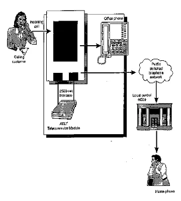
Figure 1-1. How the Module Works
Prepare for the module
Prepare for the module
■ How do you want the system set up and what hardware do you have to order and install in addition to the modules? If your module setup is loop configuration, calls loop through the phone system using system trunk and line ports. If your module setup is traverse configuration, calls traverse the system using system trunk and line ports, and go to and from the
telecommuter on a separate (nonsystem) business line. This line has forced disconnect—the line automatically disconnects after a specified amount of time.
For the loop configuration, you assign two analog extension numbers per module, line A and line B. The telecommuter dials into line A to log on to the module. The module accesses line B to the office phone system when the telecommuter makes a call. On the other hand, calls forward from the telecommuter's office phone to the module on line B. Consider putting line B in the coverage path for the telecommuter's office phone. The module uses line A to dial back through the phone system and extend the call from office to home.
For the traverse configuration, you assign one analog extension number per module, line B. You supply a separate, two-way business line with forced disconnect and label it line A. The telecommuter dials into line A to log on to the module. The module accesses line B to the office phone system when the telecommuter makes a call. On the other hand, calls forward from the telecommuter's office phone to the module on line B. Consider putting line B in the coverage path for the telecommuter's office phone. The module uses line A to extend the call from office to home.
■ How do you want the module to be accessed by the telecommuter? Depending on your system setup, your choices are (1 ) a direct inward dialing (DID) extension, (2) a live attendant, (3) an autoattendant, or (4) a separate (nonsystem) business line.
■ What calling mode do you want to use? Your choices are (1 ) per call connection, in which the connection from the module to the telecommuter is made for each call, or (2) per-session connection, in which the
connection from the module to the telecommuter is made for each logon session and stays up for as long as the telecommuter is logged on. Depending on geographic location and phone rates, per call connection is more economical for intermittent call traffic and per-session connection is more economical for heavy call traffic.
■ What security precautions do you want? Both the phone system and the module offer choices. On the phone system you can have (1 ) restrictions on telecommuters for long distance dialing or (2) restrictions on
telecommuters for all outside calls. On the module you have passwords, the Prevent feature, and dialback options.
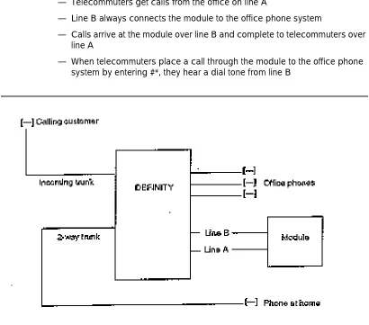
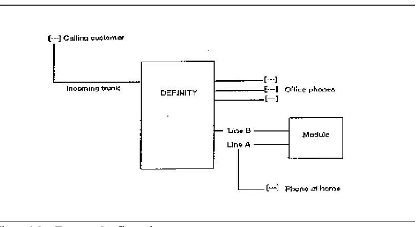
In Figure 1-2, "Loop Configuration", and Figure 1-3, "Traverse Configuration", below, lines A and B have these properties:
— Line A always connects the module to the home phone
■ The connection could be back through the office phone system (loop configuration)
■ The connection could be on a separate (nonsystem) business line (traverse configuration)
— Telecommuters call the module from home on line A
— Telecommuters get calls from the office on line A
— Line B always connects the module to the office phone system
— Calls arrive at the module over line B and complete to telecommuters over line A
— When telecommuters place a call through the module to the office phone system by entering #*, they hear a dial tone from line B
What you need for installation
Figure 1-3. Traverse Configuration
What you need for installation
Before you install the module, you or the installer have to do the following:
1. Order from AT&T one Telecommuter Module (PEC 8308-001 ) for each simultaneous telecommuter. An AC transformer and power cord, and two 7-ft mounting cords are included in each module package. Return to AT&T any items that are damaged, using the instructions in Appendix A.
2. Check that you have AC power at the location where the modules will be installed.
3. Equip the phone system with the appropriate number of trunks and analog line ports.
4. Install modular jacks for connecting the analog line ports.
5. Program the analog line ports as touch-tone 2500 phone sets.
Install the module
!
WARNING:
Important operating and maintenance instructions follow.
■ Never install phone wiring during a lightning storm.
■ Do not install phone jacks in wet locations unless the jacks are specifically designed for wet locations.
■ Do not touch uninsulated phone wires or terminals unless the phone lines have been disconnected at the network interface.
■ Use caution when installing or modifying phone lines.
Use the steps listed next to install the module.
1. Connect the AC transformer’s power cord between the module and a 120-VAC outlet. On the front panel of the module, the unlabeled green power light will flash. Be sure that the switch next to it says READY.
2. Connect phone line A to one end of a mounting cord and connect the other end of the cord to the A jack on the back of the module. Write the line-A number in this space:_________________________ .
3. Connect phone line B to one end of a mounting cord and connect the other end of the cord to the B jack on the back of the module. Write the line-B number in this space:_________________________ .
Take security precautions
Your phone system and the module offer several ways to discourage toll fraud:
■ phone system restrictions on telecommuters for long-distance calls
■ phone system restrictions on telecommuters for outside calls
■ use of the module’s Prevent feature to guard against hackers
■ use of passwords to call the module, for example:
— choose the maximum length of 10 digits
— avoid numbers that can be guessed by association such as personal or company phone numbers, names, or license plates
— change telecommuters' passwords often (twice a year at the minimum)
More security precautions
— do not enable remote programming: when remote programming is enabled, the telecommuter dialback numbers that you may have preprogrammed as a security measure are less secure. For example, if a hacker were the remote programmer, the module would be dialing back not to a telecommuter but to the hacker!
More security precautions
In addition to the security precautions listed in Chapter 1, AT&T recommends setting the answer tone to the lowest value (-16 dB). Authorized telecommuters know that they should enter a password when ringing stops but a hacker may not. Checking the volume of calls on the system every day can also be a clue to unauthorized use.
AT&T recommends that you retain the default values for the Prevent function. After five consecutive, invalid, password attempts, any password is rejected, even a valid one, for 20 minutes. A hacker doesn't know that Prevent is activated and, after dialing the right password and getting no answer, assumes that the password is bad.
You can reprogram the module to respond to invalid password attempts either by ignoring all passwords, responding with an error tone, or failing to answer.
Programming quick start
Next are the programming steps to get started using the module right away. If you follow these steps, the module will be working in a few minutes and
telecommuters can access all the phone system options available to onsite users who have an analog 2500 phone set. You can tailor the module to your
application at any time by consulting the numbered list of options (called functions in this book) in Chapter 3. You can tailor the module for use in a call center by adjusting the commands according to the information under ‘‘Special cases: timeout and DEFINITY call center’’ in Chapter 2.
Figure 1-4. Front and Back Panels
Here are the quick-start steps:
1. Set the front panel switch to PROGRAM until the unlabeled green power light shown in Figure 1-3, below, flashes quickly. The switch is the toggle type and has three positions:
a. READY = flashing green light
b. PROGRAM = quickly flashing green light
Programming quick start
Figure 1-4 also shows lights A and B, the red, in use lights for lines A and B. They light steadily when one or both lines are being used.
The module remains in programming mode until you either enter ##, hang up, let 2 minutes pass without entering any digits, or enter *88# to go into command mode. Remember that when you are programming the module, you are disconnected if 2 minutes go by and you haven’t entered a digit. The front panel switch goes back to READY when you exit programming mode.
2. Enter the module’s line-A phone number and listen for a confirmation tone of three beeps.
3. The system administrator might or might not be at the same location as the module—for example, in another room (remote) or at another location (offsite). If you need to program the module remotely or from an offsite location, ask someone who is onsite to press the front panel switch to PROGRAM. Enable remote programming by entering *98*1#
Once the module is in programming mode and you have enabled remote programming, you can access the programming function remotely at any time. Note that for security, you have to weigh the convenience of remote programming against the increased risk of toll fraud. AT&T does not recommend using the remote programming function.
4. Assign a unique, 8- , 9- , or 10- digit user-1 password for the system administrator by entering *1*1*NN...N#*1*1*NN...N#, as shown here. (In these instructions, the system administrator and the telecommuters are called users for convenience.) Choose the maximum length of 10 digits. The longer the password, the more secure the system. Do not end a password with 000.
5. Listen for a confirmation tone of three beeps signaling that the password was accepted; then choose one of the following:
a. If you entered the password successfully, continue with Step 6.
b. If you misdial and have not yet entered #, cancel the entry by entering 000#. (The module does not respond until you enter #.) When you hear an error tone, return to Step 4.
6. Check the password by entering:
*77*1*1#
Listen for the word one, then beep <the rest of the digits in the password> beep beep beep. (When you make a query, you hear a recording of the human voice say the word for each digit.) To delete the user-1 password for any reason, enter *1*1*#*1*1*#
7. Choose one of the following:
8. Assign a unique, 8- , 9- , or 10-digit user-2 password by entering
*1*2*NN...N#
9. Listen for a confirmation tone of three beeps signaling that the password was accepted; then choose one of the following:
a. If you entered the password successfully, continue with Step 10.
b. If you misdial and have not yet entered #, cancel the entry by entering 000#. (The module does not respond until you enter #.) When you hear an error tone, return to Step 8.
10. Check the user-2 password by entering *77*1*2#
Listen for the word two, thenbeep<the rest of the digits in the password> beep beep beep. To delete the user-2 password for any reason, enter
*1*2*#
11. Exit programming mode by entering the control command ## to
disconnect. Listen for a confirmation tone of three beeps, then hang up. If you don’t enter ## in programming mode before you hang up, the module automatically disconnects after a specified amount of time. But if you routinely enter ## before hanging up, you don’t have to wait for the forced disconnect before you can redial the module.
12. The module is ready to use. Enter the module’s line-A phone number, listen for a 2-second answer tone and, within 15 seconds after the answer tone stops, enter a telecommuter (user-2) password, followed by # Listen for two beeps signaling that the password was accepted and then a beep every 5 seconds. You are in command mode.
13. Make a call by entering the control command for connect #* (the default), wait for a dial tone, and enter a phone number. When you enter control commands, the digits you enter must follow each other within the
programmed time period (the default is 1 second) or the module ignores the code.
14. Enter the control command ## to hang up the outgoing line. Listen for two beeps. The green A light stays lit and the red B light turns off.
15. Hang up. The A light turns off in about 20 seconds.
Now you and your office’s telecommuters can start using the module!
Getting help if you need it
2
Handling Calls
This chapter tells you how to handle calls as a telecommuter. It also helps you answer telecommuters’ questions about how the module works. When you installed the module, you noted on the telecommuter quick reference any functions for which you changed the default values. Telecommuters should have gotten their quick reference when their passwords were assigned.
Calling the module
1. Enter the module’s line-A phone number.
2. Listen for a 2-second answer tone.
3. Enter your password followed by # within 15 seconds after the answer tone stops.
Listen for two beeps signaling that the password was accepted and then a beep every 5 seconds. You are in command mode. If you are using the module in a call center, see ‘‘Special cases: timeout and DEFINITY call center’’" later in this chapter.
Receiving a call
1. When you're in command mode, incoming calls are signaled by a ringing tone through your handset or headset. Enter #* to connect to the caller.
Making a call
1. Enter #* to get a dial tone.
2. When you finish the call, enter ## to go back to command mode.
If the call doesn’t go through, try again, pressing firmly on the buttons in the keypad. If the call still does not go through, see function 12 in Chapter 3.
Transferring a call
To transfer a call, you must make a call or already be on a call, then:
1. Enter *# (switchhook flash) to put the current call on Hold and get a dial tone.
2. Enter the number of the person you want to transfer to.
3. When the person answers, enter ## (disconnect) to complete the transfer and disconnect yourself.
Conferencing
To set up a conference, you must make a call or already be on a call to the first conferee, then:
1. Enter *# (switchhook flash) to put that conferee on Hold and get a dial tone.
2. Enter the number of the third conferee.
3. Enter *# (switchhook flash) to connect all the conferees and complete the conference.
Disconnecting from a call
1. Enter ##
Disconnecting from the module
1. Enter ## and listen for one beep.
Per-call connection for the system administrator
Per-call connection for the system
administrator
Per-call connection allows telecommuters to connect to the module for each call, whereas per-session connection allows telecommuters to stay connected to the module for the period in which they are logged in. When per-call connection is turned on, telecommuters hang up after each call. When per session connection is turned on, telecommuters stay connected: if they hang up, they end the logon session. Telecommuters must have permission from the system administrator to turn on per-call connection.
When per-call connection is enabled for a telecommuter either directly or through the dialback function, both the A and B module ports disconnect until the B port rings. Then the module connects on the A port and sends the call to the
telecommuter. If the telecommuter forgets to turn off per-call connection, the system administrator has to access the module in programming mode and enter
*200#. Otherwise the same telecommuter has to redial the module and turn off per-call connection by entering *200#.
Note that some long-distance carriers may take longer than others to handle a call. Before you use per-call connection, check that your carrier doesn’t cause delays when the module calls the telecommuter’s offsite phone number.
■ To allow per-call connection, enter *51*1#
■ To disallow per-call connection, enter *51*0#
■ To turn on per-call connection using dialback, enter *50*UU*DD*...D# where UU = the user number and DD...D = the per-call
connection/dialback number. Note that you enter the same number for both dialback and per-call connection if both functions are in use.
■ To check the per-call connection/dialback number, enter *77*50*UU# Listen for a recorded voice saying the programmed number.
■ If per-call connection is enabled, you hear a low high tone instead of a beep when you disconnect and you hear two beeps for the
command-mode reminder tone.
■ To allow telecommuters to program their own number, enter *53*1#
Per-call connection for the
telecommuter
The instructions given next are also in the telecommuter quick reference.
Turning on per-call connection
If you have permission to turn on per-call connection:
1. Enter the module’s phone number and enter *100# Listen for two beeps.
2. Enter ## Listen for a low high tone.
Programming your dialback number
for per-call connection
1. Enter the module’s phone number and enter *50* <your phone number>#
Checking the number
1. Enter *77*50# and listen for a recorded voice saying your phone number.
Turning off per-call connection
1. Enter the module’s phone number and enter *200# Listen for two beeps.
2. Enter ## and listen for a short tone.
Dialback for the system administrator
You can administer the module to dial back
■ to a number you preprogram for each telecommuter
■ to one number for all telecommuters
■ to a number entered by the telecommuter
Using dialback to a number preprogrammed for the telecommuter
Using dialback to a number
preprogrammed for the telecommuter
1. Enter the module’s phone number and listen for a 2-second answer tone.
2. Enter your password within 15 seconds after the answer tone stops. Listen for two beeps every 5 seconds signaling that your password was
accepted.
3. Enter ## to disconnect.
4. When the module calls you back, enter 5 to answer the module. Listen for two beeps every 5 seconds or for a dial tone. You can now make or receive calls.
Using dialback to one preprogrammed
number
1. Enter the module’s phone number and let it ring once. (This is the default. You can change the number of rings using function 17 in Chapter 3.) Hang up.
2. When the module calls you back, enter 5 to answer the module.
3. Listen for a 2-second answer tone and enter your password within 15 seconds after the answer tone stops. Listen for two beeps every 5 seconds or for a dial tone. You can now make or receive calls.
Using dialback to a number entered by
the telecommuter
1. Enter the module’s phone number and listen for a 2-second answer tone.
2. Enter your password within 15 seconds after the answer tone stops and listen for two beeps signaling that your password was accepted.
Special cases: timeout and DEFINITY
call center
■ Timeout
— If telecommuter connection time to the module is limited by a timeout period, listen for a warning tone 16 seconds before you are disconnected. (This is the default value. You can change the value by using function 4 in Chapter 3.) If you haven't finished your call, you need to redial the module.
■ DEFINITY call center
— Note that analog 2500 automatic call distribution (ACD) phone sets are not recommended for DEFINITY call center because they do not have the feature buttons and displays that agents typically use to navigate among work modes (auto-in, manual-in, after-call work, auxiliary work). These same limitations apply to agents who work at home through the module (the best system for remote agents is actually the AT&T Home Agent®). Nonetheless, the module affords remote agents adequate capabilities.
To use the module in a DEFINITY G2 call center:
■ Administer line B on the switch as a 2500 ACD station. (See your call-center documentation for more on ACD stations.)
■ Using proc 010 word 1 field 20, input yes for ACD agent.
■ Using proc 010 word 1 field 13, input yes for permanent data protection. This frees the line immediately on disconnect.
■ Note that DEFINITY G2 doesn't allow zip tone on a 2500 set.
These are the steps for operating as a DEFINITY G2 remote agent:
1. Enter the module's line-A phone number, listen for a 2-second answer tone. Within 15 seconds after the answer tone stops, enter your password followed by # Listen for two beeps signaling that your password was accepted and then a beep every 5 seconds.
2. Enter #* to get a dial tone, then enter the ACD logon feature access code (FAC). Enter your logon ID. Enter your logon ID again. Listen for a
confirmation tone from the switch. Enter ## to return to command mode. Listen for a beep every 5 seconds.
Special cases: timeout and DEFINITY call center
4. A fluttering ring in your headset signals that you are receiving an ACD call. Enter #* to connect to the caller. When you finish the call, enter ## to go back to command mode. If the caller hangs up first, you must still enter ##
to go back to command mode. You are ready to receive the next call.
5. To log off call-center operation, enter #* to get a dial tone, then enter the logoff FAC. Enter ## to return to command mode.To disconnect from the module, enter ## and listen for one beep. Hang up.
To use the module in a DEFINITY G3 call center:
■ Administer line B on the switch as a 2500 automatic call distribution (ACD) station. (See your call-center documentation for more on ACD stations.) We recommend using manual-answer mode, which supplies ringing and needs the agent to answer the call.
■ To administer manual-answer mode, the station screen for line B must show NONE in the auto answer field. On DEFINITY G3 version 1.1 or later, you may want to tum on redirection on no answer (RONA). In a
nonvectoring environment, RONA enables an unanswered call to follow the hunt group’s coverage path. In a call vectoring environment, an unanswered call redirects to the top of the queue for this hunt group to present to another agent. Line B is put in auxiliary work mode.
These are the steps for operating as a DEFINITY G3 remote agent in manual- answer mode:
1. Enter the module’s line A phone number, listen for a 2 second answer tone. Within 15 seconds after the answer tone stops, enter your password followed by #. Listen for two beeps signaling that your password was accepted and then a beep every 5 seconds.
2. Enter #* to get a dial tone, then enter the ACD logon feature access code (FAC). Enter the split number, then enter your logon ID. Listen for a confirmation tone from the switch. Enter ## to return to command mode. Listen for a beep every 5 seconds.
3. Enter #* to get a dial tone, then enter the ACD auto in FAC. Enter the split number. Listen for a confirmation tone from the switch. Enter ## to return to command mode. Don’t hang up unless you have turned on per session connection (function 100). Otherwise you are disconnected from the module and logged off the ACD.
4. A fluttering ring in your headset signals that you’re receiving an ACD call. Enter #* to connect to the caller. When you finish the call, enter ## to return to command mode. If you don’t enter ## within 5 seconds, you hear a dial tone. This is an error message. Clear the error by entering ## to return to command mode. You’re ready for the next call.
3
Customizing the Module
The module offers a substantial set of programming functions. Some of these, covered in Chapter 1, are needed for the module to work. Others offer options for using the module in special applications such as a call center. Still others are technical and rarely used because they adjust how the module works in unusual environments such as a local central office that doesn’t supply forced
disconnect.
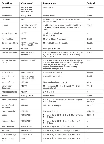
Table 3-1. Summary of Commands and Defaults
Function Command Parameters Default
passwords *1*1*NN...N# *1*1*NN...N# *1*UU*NN...N#
UU = 2 to 25 no users
answer tone *2*1#, *2*0# enable; disable enable
tone levels *3*L# L= level; L1 = 16 ± 2 dBm; L2 = -10 ± 2 dBm; L3 = -4 ± 2 dBm
L=2
timeout *4*0*TT#, *4*UU*TT; *4*0*0#, *4*UU*0#
enable all users, 0 to 99 min.; enable specific users 0 to 99 min.; disable all users; disable specific users
TT = 0
reseize-disconnect time
*6*TT# no. of sec in 10th of sec TT = 0, 5 to 30
0
idle detect time *8*TT# TT = 1 to 99 min; 0 = disable disable
dial-tone detect time
*9*TT# = specify time *9*0# = disable
TT = 0.5 to 20 sec; 0 = disable disable
amplifier gain *10*NN# NN = gain in dB, 0 to 15 NN = 5
amplifier sensitivity *11*S# = turn on threshhold
S = 0, no bits set; S = 1, + for A, - for B; S = 2, - for A, + for B; S = 3, + for A and B; S = 4, + for A; S = 5, + for B
S = 0
amplifier direction control
*12*D# = on & off D = 0, disable; D = 1, enable, off after 1st digit or voice, on after 3-sec dial tone; D = 2, on when digit detected, off after each digit; D = 3, on after ringtrip, switchhook flash, reseize, entering command mode; off at #
D = 1
modem detect *13*1#, *13*0# 1 = enable; 0 = disable disable
standard ringing only
*16*1# = enable *16*0# = disable
1 = enable; 0 = disable disable
number of rings *17*RR# RR = number of rings, 1 to 16 RR = 1
busy/reorder disconnect
*18*TT# TT = 0, disable; TT = 1 to 4, invalid; TT = 5 to 20 sec, set interval
TT = 0
initial access mode *19*D# D = 0, 1, or 2 0
Prevent *25*1#; *25*0# enable; disable enable
Prevent’s response *26*R# R = 0, ignores passwords; R = 1 doesn't respond; R = 2, error tone
0 = ignore passwords
number of invalid passwords
*27*NN# NN = 1 to 20 attempts NN = 5
Prevent's duration *28*MM# MM = min, 1 to 20 MM = 20
reseize *34*N*DDD# N = no. of digits; DDD = 0, 2, or 3, 0 to 9 or * or #; N = 0, disable
DDD = 0
switchhook flash *35*N*DDD# N = no. of digits; DDD = 2 or 3, 0 to 9 or * or #; N = 0, disable
*#
tone elimination *36*N*DDD# N = no. of digits, 2 or 3, 0 to 9 or * or # **
go to command mode
*88# N = no. of digits; DDD = 2 or 3, 0 to 9 or * or # ##
milliwatt test *40*NNN# = enable; *40*0# = disable
NNN = 0 to 300
interdigit time *41*DD# DD = 1 to 20 0
reminder tone *42*DD# 5 = enable, 4 to 60 DD = 5
per-call connection/ dialback number
*50*UU*DD# DD...D = PCC/DB number
per-call connection *51*1#, *51*0# = disable
0 = disable; 1 = enable disable
dialback *52*D# D = 1, not used; D = 2, calls dialback no. for logged-on user; D = 3, calls dialback no. for any user; D = 4, calls dialback no. entered by user
disable
per-call connection/ dialback permission
*53*0#, *53*1# 0 = 0, disable; D = 1, enable D = 0
programming query *77*FF# = value *77*FF*UU# = value & user no.
ask for function value none
test tones *80*D# = produce test tone; *81*D# = produce 20-sec answer tone
D = 1 to 9 for 20 sec; D = 10, 0; D = 11, *; D = 12, # none
go to command mode
*88# none none
version query *90# none none
remote programming
*98*0#, *98*1# 0 = disable, 1 = enable disable
restore defaults *99#*99# none none
start per-call connection
*100# none none
stop per-call connection
*200# none
Table 3-1. Summary of Commands and Defaults — Continued
Function Command Parameters Default
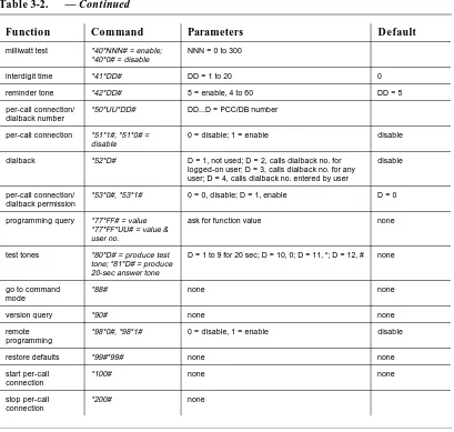
Table 3-2.
Function Command Parameters Default
passwords *1*1*NN...N# *1*1*NN...N# *1*UU*NN...N#
UU = 2 to 25 no users
answer tone *2*1#, *2*0# enable; disable enable
tone levels *3*L# L= level; L1 = 16 ± 2 dBm; L2 = -10 ± 2 dBm; L3 = -4 ± 2 dBm
L=2
timeout *4*0*TT#, *4*UU*TT; *4*0*0#, *4*UU*0#
enable all users, 0 to 99 min.; enable specific users 0 to 99 min.; disable all users; disable specific users
TT = 0
reseize-disconnect time
*6*TT# no. of sec in 10th of sec TT = 0, 5 to 30
0
idle detect time *8*TT# TT = 1 to 99 min; 0 = disable disable
dial-tone detect time *9*TT# = specify time *9*0# = disable
TT = 0.5 to 20 sec; 0 = disable disable
amplifier gain *10*NN# NN = gain in dB, 0 to 15 NN = 5
amplifier sensitivity *11*S# = turn on threshhold
S = 0, no bits set; S = 1, + for A, - for B; S = 2, - for A, + for B; S = 3, + for A and B; S = 4, + for A; S = 5, + for B
S = 0
amplifier direction control
*12*D# = on & off D = 0, disable; D = 1, enable, off after 1st digit or voice, on after 3-sec dial tone; D = 2, on when digit detected, off after each digit; D = 3, on after ringtrip, switchhook flash, reseize, entering command mode; off at #
D = 1
modem detect *13*1#, *13*0# 1 = enable; 0 = disable disable
standard ringing only
*16*1# = enable *16*0# = disable
1 = enable; 0 = disable disable
number of rings *17*RR# RR = number of rings, 1 to 16 RR = 1
busy/reorder disconnect
*18*TT# TT = 0, disable; TT = 1 to 4, invalid; TT = 5 to 20 sec, set interval
TT = 0
initial access mode *19*D# D = 0, 1, or 2 0
Prevent *25*1#; *25*0# enable; disable enable
Prevent’s response *26*R# R = 0, ignores passwords; R = 1 doesn't respond; R = 2, error tone
0 = ignore passwords
number of invalid passwords
*27*NN# NN = 1 to 20 attempts NN = 5
Prevent's duration *28*MM# MM = min, 1 to 20 MM = 20
reseize *34*N*DDD# N = no. of digits; DDD = 0, 2, or 3, 0 to 9 or * or #; N = 0, disable
DDD = 0
switchhook flash *35*N*DDD# N = no. of digits; DDD = 2 or 3, 0 to 9 or * or #; N = 0, disable
*#
tone elimination *36*N*DDD# N = no. of digits, 2 or 3, 0 to 9 or * or # **
■ Begin each command with an asterisk (*) and end it with a pound sign (#). Note that the first 1 to 2 digits surrounded by asterisks in every command are the function number. When the user number is part of the command as in the password command, that number follows the function number, also surrounded by asterisks. (In these instructions, telecommuters are called users.)
■ For functions that are assigned to all telecommuters, use the format:
*<function number>*<value you want for that function>#
■ For functions that are assigned to individual telecommuters, use the format:
*<function number>*<user ID number>*<value you want for that function>#
milliwatt test *40*NNN# = enable; *40*0# = disable
NNN = 0 to 300
interdigit time *41*DD# DD = 1 to 20 0
reminder tone *42*DD# 5 = enable, 4 to 60 DD = 5
per-call connection/ dialback number
*50*UU*DD# DD...D = PCC/DB number
per-call connection *51*1#, *51*0# = disable
0 = disable; 1 = enable disable
dialback *52*D# D = 1, not used; D = 2, calls dialback no. for logged-on user; D = 3, calls dialback no. for any user; D = 4, calls dialback no. entered by user
disable
per-call connection/ dialback permission
*53*0#, *53*1# 0 = 0, disable; D = 1, enable D = 0
programming query *77*FF# = value *77*FF*UU# = value & user no.
ask for function value none
test tones *80*D# = produce test tone; *81*D# = produce 20-sec answer tone
D = 1 to 9 for 20 sec; D = 10, 0; D = 11, *; D = 12, # none
go to command mode
*88# none none
version query *90# none none
remote programming
*98*0#, *98*1# 0 = disable, 1 = enable disable
restore defaults *99#*99# none none
start per-call connection
*100# none none
stop per-call connection
*200# none
Table 3-2. — Continued
■ For example, to assign passwords for users 2 through 25, you would enter: *1*UU*NN...N# where UU is the user number, in this case 2 through 25, and NN...N is the unique password of 8, 9, or 10 digits. After you enter a command, wait for a confirmation tone of three beeps. An error tone instead means that you have entered an invalid command.
■ Variables are: D = digits, F = function, L = level, M = minutes, R = response or rings, S = sensitivity, T = time, U = user.
■ Programming worksheets are supplied for your convenience. Fill out one worksheet for each telecommuter with the values you have chosen for each function. (An example of a filled-out worksheet is shown in Table 3-3, next.) Keep the worksheets for your own reference, storing them in a safe place away from the module.
Table 3-3. Programming Worksheet
Line-A phone number _________________________ Line-B phone number _________________________
User ID Password PCC/DB number Timeout
1 047551709 91 201 957 4331
2 5031066830 91 718 529 2060
3 1640147265 91 212 766 8141
Function 1: passwords
Purpose: Passwords for telecommuters are necessary for security. Although the default is that no passwords are assigned, if you don’t assign passwords, the module denies access to all telecommuters. User 1 is reserved for remote programming (if it is activated, using function 98).
A password can be any unique sequence of 8, 9, or 10 digits (the maximum number,10, is recommended for security). You can assign up to 25 passwords for telecommuters, beginning with user 2.
Parameters: UU = 2 to 25
Commands:*1*1*NN...N#*1*1*NN...N# = assign a password for user 1; *1*UU*NN...N# = assign passwords for users 2 to 25
Function 2: answer tone
Purpose: This function signals telecommuters that they can enter a password; you can disable the answer tone to confuse hackers.
Parameters: enable or disable
Commands: *2*1# = enable answer tone (default); *2*0# = disable answer tone
Function 3: tone levels
Purpose: This function sets the volume for the answer tone, voice responses, and ringing produced by the module.
Parameters: level 1 = -16± 2 dBm; level 2 = -10 ± 2 dBm (default); level 3 = -4 ± 2dBm
Function 4: timeout
Purpose: This function sets a limit on the time telecommuters can be logged in to the module.
Parameters: 0 to 99 minutes
Commands:
*4*0*TT# = enable for all users; *4*UU*TT# = enable for specific users
*4*0*0# = disable for all users; *4*UU*0# = disable for specific users
Function 6: reseize-disconnect time
Purpose: This function is used to set the module’s disconnect time to match the switch’s requirement.
Parameters: the number of seconds allowed, measured in 10ths of seconds, after you disconnect and until you reconnect—for example, *6*18# = 1.8 seconds, the recommended value
Command: *6*TT# (TT = 0, default, 5 to 30)
Function 8: idle detect time
Purpose: This function prevents line A from getting "hung"—not disconnecting, which locks out the next telecommuter to call the module. This happens if you hang up without entering ## and your local central office doesn't supply forced disconnect. (See also functions 9 and 18.)
Parameters: TT = 1 to 99 minutes; 0 = disable (default, number of minutes of silent time on the line before you are disconnected)
Function 9: dial tone detect time
Purpose: This function automatically disconnects after dial tone has been present for a specified time. In some installations, including those in which line A is loop start and your local central office doesn’t supply forced disconnect, the module may not be able to disconnect without this function. (See also functions 8 and 18.)
Parameters: TT = 0.5 to 20 seconds; disable = 0 (default)
Commands:*9*TT# = specify time; *9*0# = disable
Function 10: amplifier gain
Purpose: Use the default gain value for this function unless telecommuters complain of low volume. Then increase the value by 3 until you get the right level without causing dialing errors. If necessary, fine tune by 1 -dB increments.
Parameters: NN = gain in dB, 0 to 15; default = 5
Command:*10*NN#
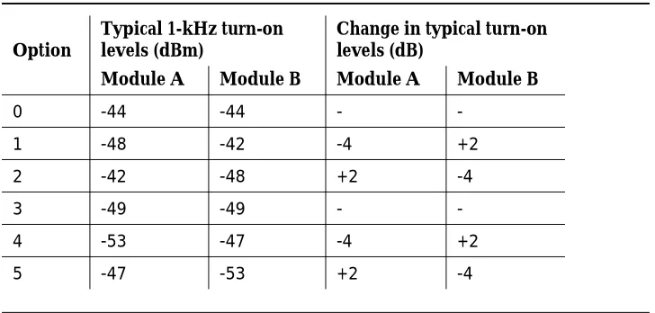
Function 11: amplifier sensitivity
Purpose: This function sets the typical threshholds at which the amplifier tums on. Use it if low-level signals are not strong enough. First enable function 10.
Parameters: You can lower typical thresholds for either or both the A and B sides. For example, the amplifier turns on when transmission levels for either the A or the B sides are -44 dBm or lower (S = 0). Setting the level to S = 1 increases sensitivity from the A side (-48 dBm) and decreases sensitivity from the B side (-42 dBm).
S = 0, no sensitivity bits set (default)
S = 1, + for A, - for B
S = 2, - for A, + for B
S = 3,+ for A and B
S = 4, + for A
Function 12: amplifier direction control
Purpose: This function ensures that the amplifier doesn’t raise the level of the dial tone and attenuate the level of the dialed digits. It raises the level only on the A side while the telecommuter is dialing, then turns off and lets the amplifier work normally.
Change the value of this function if needed to break dial tone. First enable function 10.
Parameters:
■ Direction control is turned on after any of the following:
— ringtrip
— switchhook flash
— sending a connect command from command mode
— reseizing
■ When set to 1, direction control turns off automatically when voice is detected; it turns on after 3 seconds of dial tone
Table 3-4. Amplifier Sensitivity Options
Option
Typical 1-kHz turn-on levels (dBm)
Change in typical turn-on levels (dB)
Module A Module B Module A Module B
0 -44 -44 -
-1 -48 -42 -4 +2
2 -42 -48 +2 -4
3 -49 -49 -
-4 -53 -47 -4 +2
■ Direction control also turns on when 3 seconds of busy or reorder tone are detected; it doesn’t tum off until you flash the switchhook or go into command mode
■ Change the value of this function if you have trouble breaking dial tone; the default is enabled
— D = 0, disable
— D = 1, enable (default), turns off after the first digit ends or when voice is detected, and turns on after 3 seconds of dial tone; this works in most cases where direction control is needed
— D = 2, turns on when a digit is detected and turns off after each digit ends
— D = 3, turns on after a ringtrip, a switchhook flash, a reseize, and when you enter command mode; turns off when you enter #
Command: *12*D# = turn direction control on and off
Function 13: modem detect
Purpose: This function allows the module to detect a 2225-Hz modem tone and disable the amplifier to prevent interference with data transmission.
Parameters: 1 = enabled; 0 = disable (default)
Commands: *13*1# = enable; *13*0# = disable
Function 16: standard ringing only
Purpose: Use this function to program the module so that it responds to the standard ring of 2 seconds on and 4 seconds off and ignores any calls that don't match this pattern; this function is automatically disabled when the module is in programming mode.
Parameters: 1 = enable; 0 = disable (default)
Function 17: number of rings
Purpose: This function sets the number of rings needed before the module answers; when you set the front panel switch on the module to PROGRAM, the first call after you set it is answered on the first ring. (See also function 52.)
Parameters: RR = number of rings,1 to 16; default = 1
Command:*17*RR#
Function 18: busy/reorder disconnect
Purpose: This function specifies the number of seconds (5 to 20) that a busy or reorder tone lasts before the module disconnects. (See also functions 8 and 9.)
Parameters:
TT = 0 disables the function (default)
TT = 1 to 4 are invalid; the telecommuter hears an error tone
TT = 5 to 20 enable the function and set the interval before the disconnect; 1 0 is the suggested value
Command:*18*TT#
Function 19: initial access mode
Purpose: This function lets you choose how the module works (the mode) when you enter a valid password:
■ in mode 0 (default), you enter command mode and hear beep beep every 5 seconds
■ in mode 1, you hear a dial tone from the switch; you can place calls with tone elimination enabled; this mode is seldom used
■ in mode 2, you hear a dial tone from the switch; you can place calls with tone pass-through enabled; this is the mode needed for using the module in a call-center environment
Parameters: D = 0, 1, or 2
Function: call center
See ‘‘Special cases: timeout and DEFINITY call center’’ in Chapter 2.
Function 25: Prevent
Purpose: This function prevents all telecommuters from calling the module after repeated tries to enter an invalid password, as specified in functions 26, 27, and 28. If Prevent is enabled and you keep the default values for functions 26, 27, and 28, whenever the module gets five consecutive invalid passwords it blocks further access by any telecommuter for 20 minutes by ignoring all passwords.
Parameters: enable (default) or disable (this is not recommended)
Command: *25*1# = enable (default); *25* 0# = disable
Function 26: Prevent’s response
Purpose: This function specifies the response to callers when function 25 is activated.
Parameters:
R = 0, module ignores passwords (default)
R = 1, module doesn't respond
R = 2, module responds with an error tone
Function 27: number of invalid passwords
Purpose: This function sets the number of consecutive invalid passwords attempted before function 25 is activated
Parameters: NN = 1 to 20 attempts; default = 5
Command:*27*NN#
Function 28: Prevent’s duration
Purpose: This function sets the number of minutes Prevent is active; longer intervals mean more security
Parameters: MM = number of minutes, 1 to 20; default = 20
Command:*28*MM#
Function 34: reseize
Purpose: This function creates one control command that combines the functions of disconnecting from one call (##) and getting a dial tone to start a new call (#*). Function 6 sets the interval during which the line is disconnected.
Parameters: N = number of digits in command; DDD = 0, 2, or 3 digits; valid entries are 0 to 9 or * or #; default = 0; if N = 0, the function is disabled
Command: *34*N*DDD#
Function 35: switchhook flash
Purpose: This function changes the default command for switchhook flash.
Parameters: N = number of digits in control command; DDD = 2 or 3 digits, valid entries are 0 to 9 or * or #; default = *#; if N = 0, the function is disabled
Function 36: tone elimination
Purpose: This function changes the default command for tone elimination.
Parameters: N = number of digits in control command; DDD = 2 or 3 digits, valid entries are 0 to 9 or * or #; default = **
Command:*36*N*DDD#
Function 37: disconnect
Purpose: This function changes the default command for disconnect.
Parameters: N = number of digits in control command, valid entries are 9 to 0 or * or #: default = ##; if N = 0, the function is disabled
Command: *37*N*DDD#
Function 38: tone pass through
Purpose: This function changes the default command for tone elimination.
Parameters: N = number of digits in control command; DDD can be 2 or 3 digits, valid entries are 0 to 9 or * or #; default = #*
Command:*38*N*DDD#
Function 39: go to command mode (command)
Purpose: This function changes the default command to "go to command mode.”
Parameters: N = number of digits in control command; DDD = 2 or 3 digits; valid entries are 0 to 9 or * or #; default = ##
Function 40: milliwatt test
Purpose: This function causes the module to connect, then disconnect, after hearing 1004 Hz for the specified number of seconds (0 through 300). Enable this function if the module can’t release a line in response to a milliwatt test number.
Parameters: NNN = 0 to 300; default = 15
Command:*40*NNN# = enable; *40*0# = disable
Function 41: interdigit time
Purpose: This function changes the interdigit time for control commands.
Parameters: DD = 1 to 20
Command:*41*DD#
Function 42: reminder tone
Purpose: This function causes the module to beep once at a specified interval (4 to 60) while you are in command mode. If per-call connection is enabled and a telecommuter is logged in, the module beeps twice at the specified interval.
Parameters: 5 = enable (default), 4 to 60
Command:*42*DD#
Function 50: per-call connection/dialback number
Purpose: This function programs the per-call connection/dialback number (the number at the telecommuter’s location)
Parameters: DD...D = PCC/DB
Function 51: per-call connection
Purpose: This function allows the module to forward office calls to the
telecommuter, one call at a time. In this way, telecommuters hang up after each call to reduce network facility expense. If you enable this function, telecommuters can activate per-call connection with function 100 and deactivate it with function 200.
Parameters: 0 = disable (default); 1 = enable
Command: *51*1#
Function 52: dialback
Purpose: This function allows the system administrator to choose a dialback mode for telecommuters. The module can dial back to a number you set for each telecomuter, to one number for all users, or to a number entered by the
telecommuter. Passwords are always needed.
Parameters:
D = 0, disable
D = 1, not used
D = 2, module calls dialback number for a logged on telecommuter, administered using function 50
D = 3, module calls one dialback number for any telecommuter administered using function 50
D = 4, module calls dialback number entered by a telecommuter, using function 50, if allowed by the system administrator, using function 53
Commands:*52*D#
Function 53: per-call connection/dialback
permission
Purpose:
This function grants or denies permission for telecommuters to change their PCC/DB number.
Parameters: D = 0, disable (default); D = 1, enable
Function 77: programmmg query
Purpose: This function allows you to ask for the value of any function you have programmed and get a recorded voice response.
Commands:*77*FF# = value; 77*FF*UU# = value and user number
Functions 80 and 81: test tones
Purpose: Use this function to listen to and test the tones for each digit entered and the answer tone.
Parameters:
D = 1 to 9, DTMF tones for 20 seconds
D = 10, 0
D =11, *
D = 12, #
Commands:*80*D# = produce a test tone; *81# = produce a 20-second answer tone
Function 88: go to command mode
Purpose: This function allows you to go right from programming mode to command mode.
Parameters: none
Function 90: version query
Purpose: This function checks the version number of the software installed.
Parameters: none
Command: *90#
Function 98: remote programming
Purpose: This function enables you to program the module from a remote location such as another room or offsite. The module has to be in programming mode. (For security, disabling this function is recommended.)
Parameters: 0 = disable (default); 1 = enable
Command: *98*1# = enable remote programming; *98*0# = disable remote programming
Function 99: restore default values
Purpose: This function erases all your values and resets the functions to the default values programmed at the factory. Are you sure you want to do this?
Parameters: none
Command: *99#*99#; 3 beeps confirm the change
Function 100: start per-call connection
Purpose: This function allows the telecommuter to activate per-call connection if you have enabled function 51.
Parameters: none
Function 200: stop per-call connection
Purpose: This function allows the telecommuter to deactivate per-call connection.
Parameters: none
4
Troubleshooting
Here are some steps to take if you have problems with the module. If these steps don’t work, call AT&T at:
Technical Service Center (TSC)
800-242-2121
National Service Assistance Center (NSAC)
800-628-2888
Problem: The module doesn’t answer.
Solution: Check the unlabeled green power light on the front panel of the module.
■ If the green light does not flash:
— Check that the front panel switch is set to READY.
— Check that the module is plugged in.
— Ask a qualified technician to unplug the power cable from the wall and check that there are 120 VAC ±10% at the wall receptacle and, if the wall receptacle is on a switched outlet, that the switch is on.
■ If this voltage is not present, the problem is an open circuit breaker or faulty building wiring: get it fixed.
■ If this voltage is present, check that there are a minimum of 12 VAC at the power cable connector and reconnect the module.
■ If the green light does flash:
— Unplug line A from the module and plug it into an analog phone instead.
— Enter the line-A phone number from another phone.
■ If this phone doesn't ring, check the number and redial.
■ If the phone still doesn't ring, the problem is in the wiring: get it fixed.
■ If the phone does ring, answer it to check the connection. The problem is not in the wiring. Unplug the phone and reconnect the module.
— Press the front panel switch to PROGRAM until the green light flashes quickly (programming mode) and enter the module's line-A phone number within 5 minutes.
■ If the module doesn't answer in programming mode—the red light (light A) doesn't light or you don't hear a confirmation tone of three beeps—the module is defective: return it to AT&T.
■ If the module does answer in programming mode—the red light (light A) lights and you hear a confirmation tone of three beeps—query function 16, standard ringing only, by entering *77*16# to check that it is disabled. If you hear a recorded voice say zero, the module is defective in normal mode: return it to AT&T.
Problem: the module answers but doesn't respond with an answer tone.
Solution: query function 2, answer tone, to check that it is enabled. If it is enabled, set the answer tone to the loudest value (level 3).
Problem: the module does not seize line B.
Solution: check that line B supplies a dial tone.
■ If the red light (light B) doesn't light when you try to make a call by entering #*, the module is defective: return it to AT&T.
■ If the red light (light B) does light but you don't hear a dial tone, unplug line B from the module and plug it into an analog phone instead. Use this phone to make a call. If you get a dial tone, the module is defective: return it to AT&T.
Problem: the red light (light A) flashes and immediately fades.
Problem: when you make a call, the dial tone doesn’t stop after you enter the first digit.
Solution: check line B and function 10, amplifier gain.
■ Unplug line B from the module and plug it into an analog phone instead.
A
Warranty and Returns
■ Warranty: AT&T warrants this product to be free from defects in material and workmanship for a period of 12 months from the date of purchase, given proper installation and use. At its sole discretion, AT&T will repair or replace free of charge any module found to be defective during the warranty period. Modules found to be defective beyond the warranty period will be repaired or replaced at a flat rate.
■ Toll fraud disclaimer: while the module is designed to be reasonably secure from intrusions by fraudulent callers, it is by no means invulnerable to fraud. Therefore, AT&T makes no express or implied warranty against such fraud.
■ Returns: if a module is found to be defective, contact your AT&T account executive. Note that the phone company may ask you to disconnect the module from the network until the problem has been corrected or until you are sure that the module is not malfunctioning. If you need more
information, call AT&T at:
Technical Service Center (TSC)
800-242-2121
National Service Assistance Center (NSAC)
B
Programming Worksheet
Line-A phone number _________________________ Line-B phone number _________________________
User ID Password PCC/DB number Timeout Notes
C
Specifications
Main Board
!
WARNING:
Important operating and maintenance instructions:
Power needs (use only with class-2 power source rated 120-VAC, 60-Hz, 10W input; 12-VAC, 500-mA output):
Input 120 VAC ± 10%
Output 12V, 500 mA nominal
Operation During Power Loss
Ringing Voltage Detection
With standard ringing only 40-150 VRMS at 16-66 Hz applied to T-R
disabled for > 400 ms
With standard ringing only 40-150 VRMS at 16-66 Hz applied to T-R enabled with cadence of 2000 ±220 ms on, 4000 ±
440 ms off (6 sec needed to answer call)
Insertion Loss
With amplifier (set for 0 dB gain) < 2.5 dB for 300-3500 Hz
Longitudinal balance > 60 dB for 200-1000 Hz > 50 dB for 1000-4000 Hz
Loop Limitations
Input port loop start
Output port loop start
Seizure ≥20 mA minimum
≤100 mA maximum Maximum break duration with no < 350 ms (input port only) loss of seizure
DTMF Receive Detect
Tone duration must accept > 40 ms must reject < 20 ms
Tone level composite signal must accept ≥ 25 dBm must reject ≤ 37 dBm
Twist ±6 dB
DTMF Transmit Signals
DTMF Transmit Signals
Tone duration 70 ±5 ms
Interdigit time 70 ±5 ms
Tone level -6 ±4 dBm
Minimum break for guaranteed > 550 ms (input port only) loss of seizure
Input Impedance
DC 210 ±30 ohms (after seizure)
AC 925 ±75 ohms (before password and with
outgoing line split)
Output Impedance
DC 210 ±30 ohms (after seizure)
AC 925 ±75 ohms (with the A side open)
Passwords
Passwords (8-10 digits, any detects and accepts (see "DTMF receive combination of DTMF digits 0-9) detect"); # at end of password must be
entered within 16 sec of answer tone (if enabled) or unit disconnects; error tone is returned 16 sec after the last DTMF digit entry
Seizure of Outgoing Line
Control Commands
Connect mode signal takes unit out of command mode and into connect mode (defaults = tone pass-through, #*, or tone elimination **)
Disconnect in command mode, causes unit to disconnect (default = ##)
Switchhook flash opens outgoing line for 550 ±50 ms (default = * #)
Command mode outgoing line is on-hook and user is connected to A port (default = ##)
Reseize sends an on-hook signal to B port (default = disabled)
Disconnect timer programmable for 1 to 99 minutes; timer starts at cut through; warning tone 16 sec before disconnect
Call-Progress Tone Detection
Dial tone detect zero crossing detector finds presence of tones from 305 to 640 Hz with level > -27 dBm and rejects all signals below -27 dBm
1000 Hz tone detect zero crossing detector finds presence of 1000 Hz tone; must accept 1000 ±50 Hz at level > -27 dBm; must reject tone < 900 Hz and tone > 1100 Hz and any tone below -37 dBm
Call-Progress Tone Detection
Data disable detect from microprocessor sets gain to 0 after amplifier detecting 2225 Hz ±100 Hz for 350 ±100
ms; gain remains at 0 until module is reset or output line is dropped and reseized
Test tone detect normally disabled; when enabled, unit disconnects on detection of 1000-Hz tone for 1 to 300 sec
Idle detect normally disabled; when enabled, unit does switchhook flash on detecting no activity on line for programmable period of 1 to 99 min, then looks for tone of 305 to 640 Hz for 5 sec, then disconnects incoming and outgoing lines; must accept 305 < sig < 640; must reject 300 > sig > 645
Error tone alternates high and low tones for 2 sec (notifies user of error in programming or password)
Answer tone none
With answer tone disabled none
With answer tone enabled begins 2.0 ±0.1 sec after ring trips; lasts 2.0 ±0.1 sec; level (programmable) at -4 ±2 dBm, 10 ±2 dBm (factory setting), or -16 ±2 dBm, frequency 440 ±10 Hz
Confirmation tone 3 short beeps, 250 ms duration
Voice Amplifier
Gain software selectable in 1 -dB increments from 0 to 15 dBm ±1 dB, measured with input -30 dBm
Maximum output with gain with input signal below -9 dBm: -9 dBm with input signal above -9 dBm: tracks input signal level
Gain between 500 and 330 Hz ±1 dB of gain at 1000 Hz
Gain at 300 Hz does not deviate by more than -3 dB from gain at 1000 Hz
Data disable signal microprocessor detects disable tone and disables amplifier; amplifier stays disabled until unit is reaccessed or a retrial is initiated on the outgoing line; must detect 2225 Hz ±21 Hz lasting 350 ±100 ms + signal > - 30 dBm; must reject 2450 < signal < 2000 Hz
Voltage sensitivity thresholds see function 11, amplifier sensitivity
Longitudinal balance, as > 60 dB for 200-1000 Hz measured by IEEE Standard > 50 dB for 1000-4000 Hz 455-1976
Singing point unconditionally stable
Overload does not occur until signal on output is +9 dBm at 1 kHz
Harmonic distortion < 1 % between 500 and 3300 Hz with signal and source-load impedances of 900 ohms, input signal at 0 dBm, and gain set to +7 dBm
Turn-on time < 5 ms when input signal of 1 kHz at -30 dBm is applied and unit gain is set for +7 dB
Mechanical Specifications
Mechanical Specifications
Unit dimensions 1.5" x 5.5" x 9"
Indicators and controls 3 LEDs on front panel: A is red when incoming line is seized; B is red when outgoing line is seized; power light is flashing green when module is enabled, quickly flashing green when in
programming mode, off when disabled; 3-position switch on front panel enables or disables module or puts it in
programming mode
Power and line connections 2 RJ-11C jacks on back panel connect incoming and outgoing lines; an AC power jack and an RS-232-C port connect a printer for recording calls
Line needs line-port B to switch is loop start; line-port A to telecommuter is loop start with forced disconnect
Polarity line-ports A and B are protected against polarity: if T and R are reversed, the module still works
Environmental Specifications
Temperature 0-55°C
Relative humidity operates at 55°C and 85% relative
humidity (noncondensing) for 72 hr with no degradation of performance
Regulatory Compliance
D
Sample Call Records
Table D-1. Sample Call Records
Field 1 Field 2 Field 3 Field 4 Explanation
NO CODE, , ONHOOK, User called the module, got an
answer tone, and hung up
NO CODE, , DTMF T/O, User called the module, didn’t enter digits, and after 16 sec the module disconnected
DENIED, , , User called the module, entered
invalid password digits, and the module disconnected
PROGRA M
##, Module was accessed for
programming by the user-1 password or the PROGRAM switch, and the control command ## (disconnect) was used
USER 02, 5551212, ONHOOK ,00:00:15 User 2 entered 555-1212 and hung up after 15 sec
USER 02, 5551212##, ,00:00:15 User 2 entered 555-1212 and entered ## to go to command mode
USER 02, 5551212**, ,00:00:15 User 2 entered 555-1212 entered **, and the module disconnected after 15 sec
USER 02, 5551212, TIMEOUT ,00:20:15 User 2 entered 555-1212 and the module disconnected when timeout was exceeded
USER 25, 5551212, IDLE T/O ,00:05:15 User 25 entered 555-1212 and the module disconnected when the idle detect time elapsed
USER 25, 5551212, REORDER T/O
,00:02:05 User 25 entered 555-1212, the module got a reorder tone and disconnected
USER 25, 5551212, BUSY T/O ,00