1Banothu BalaSubramanyam, 2Boilla Srinu
1M.tech Student Dept. of EEE, Madhira institute of technology & sciences, Telangana, India
2Assistant professor,Dept. of EEE, Madhira institute of technology & sciences, Telangana, India
Abstract: This paper grants a design and simulation of modulation and Fuzzy control strategies are plays main role to diminish THD in Multilevel inverter. These modulation techniques comprise Sinusoidal Pulse Width Modulation (SPWM) and Selective harmonic Elimination and Space Vector Pulse Width Modulation (SVPWM). Multilevel inverters have tremendous application in the area of high-power and mediumvoltage energy control. This paper presents a model simulation of Fuzzy based SVPWM is performed for cascaded H-bridge inverter in hybrid vehicles. The Simulation of various levels of cascaded H bridge inverter with Space vector PWM has been carried out.
Keywords- Pulse Width Modulation (PWM),
SPWM, Sinusoidal Pulse Width Modulation
(SVPWM).
I. INTRODUCTION
Numerous industrial applications require better power apparatus in recent years. Some medium voltage motor drives and application packages require medium voltage and megawatt power degree. As for any embedded transportation device, those energy converters are the concern to extreme constraints, specifically regarding compactness and vehicle integration. More specifically, electric vehicles (EVS) require a high diploma of availability. A multilevel electricity converter structure has been delivered as an alternative in high strength and medium voltage situations, in the end, numerous multilevel converter topologies were developed. A multilevel converter not most effective achieves excessive strength rankings but also enables using renewable energy resources. The sanctifications of three-level inverter topology over traditional -stage topology is 1)the voltage throughout the switches is best one 1/2 of the dc supply voltage 2) the switching frequency can be reduced for the equal switching
losses three)the higher output modern harmonics are reduced via the same switching frequency. The cascaded h bridge the inverter has the benefit of a discount in transfer count and more powerful use of the herbal switching velocity and voltage-blocking traits of the exceptional styles of energy digital gadgets which might be used. The maximum common the method used for the cascaded h bridge inverter is the phase shifted provider PWM, which give improved harmonic performance while every single-phase inverter is managed the usage of three-degree modulation [1].Despite the fact that the cascaded h-bridge inverter has an inherent self-balancing functionality, due to the losses in circuit thing and restrained controller decision, a mild voltage imbalance can arise. The easy manipulate block with pi regulator to regulate the trigger angle and to ensure zero steady-nation errors among the reference dc voltage and the dc-bus voltage can make sure the dc voltage stability, reactive and harmonic compensations [2]. An automatic voltage stability can be performed by way of supplying voltage to cascaded h bridge inverter by using the use of a the high-frequency link which generates all of the isolated dc supplies. Therefore low and constant THD in any respect running degrees may be obtained [3]. The cascaded h bridge multilevel the inverter may be used for high electricity packages with novel
The mmc-based total frequency converting
conversion scheme [4-9]. In this paper, a specific fault-tolerant drive topology patented by Valeo agency [10], [11] is studied. It allows each traction and charger operating modes with the identical electricity digital devices [12], [13]. Furthermore, the traction working mode is fault tolerant as it is able to function with best two stages of the electric device. The considered topology makes use of six half bridges in place of the classical use of three half of bridges, leading to manipulate strategies which are a whole lot extra complicated but offer new voltage
configurations. Therefore, these tiers of freedom are used to design new manipulate methods and will be compared with classical methods on this paper. The subsequent trouble is to analyze whether the progressive control methods may be reconfigured in a switch failure case. Both displays are primarily based on space vector pulse width modulation (SVPWM) method, which allows the proper analysis of this discrete manipulate problem and to synthesize suitable manipulate techniques. Finally both classic and innovative strategies are implemented in numerical simulation.
Variable voltage and frequency supply for Adjustable Speed Drives (ASD) is invariably obtained from a three‐phase VSI. In electronic power converters and motors, PWM is used extensively as a means of powering alternating current (AC) devices with an available direct current (DC) source or for advanced DC/AC conversion. Variation of duty cycle in the PWM signal to provide a DC voltage across the load in a specific pattern will appear to the load as an AC signal, or can control the speed of motors that would otherwise run only at full speed or off. The pattern at which the duty cycle of a PWM signal varies can be created through simple analog components, a digital microcontroller, or specific PWM integrated circuits.
Figure‐2 shows the input reference waveform (square wave) and a carrier wave (triangular wave) is passed into a comparator to achieve the PWM waveform. The triangular wave is simple to create, utilizing an op‐amp driver. The triggering pulses are generated at the instants of the carrier signal magnitude is greater than the reference signal magnitude. The firing pulses are generated to turn‐on the IGBT switches so that the output voltage is available during the interval triangular voltage wave exceeds the square modulating wave. The advantages possessed by PWM technique are,
(i) The output voltage control with this method can be obtained without any additional components.
(ii) With this method, lower order harmonics can be eliminated or minimized along with its output voltage control. As higher order harmonics can be filtered easily, the filtering requirements are minimized.
The main disadvantage of this method is that the inverter switches are expensive as they must possess low turn‐off and turn‐on times.
Types of pwm techniques: A number of PWM techniques are there to obtain variable voltage and frequency supply such as,
(i) Single‐pulse modulation (ii) Multiple‐pulse modulation
(iii) Selected harmonic elimination PWM (iv) Minimum ripple current PWM
(v) Sinusoidal‐pulse PWM (SPWM)
(vi) Space vector‐pulse PWM (SVPWM)
i. Single Pulse Modulation: When the waveform of output voltage from single phase full‐bridge inverter is modulated, it consists of a pulse of width 2d located symmetrically about π/2 and another pulse located symmetrically about 3π/2. The range of pulse width 2d varies from 0 to π; i.e.0<2d<π. The output voltage is controlled by varying the pulse width 2d. This shape of the output voltage wave is called quasi‐square wave.
ii. Multiple‐pulse modulation: This method of pulse
modulation is an extension of single‐pulse
modulation. In this method, several equidistant pulses per half cycle are used.
iii. Selected harmonic elimination PWM: The undesirable lower order harmonics of a square wave
can be eliminated and the fundamental voltage can be controlled as well by what is known as selected harmonic elimination (SHE) PWM. A large no. of harmonics can be eliminated if the waveform can accommodate additional notch angles.
II. PROPOSED CONTROL SCHEME
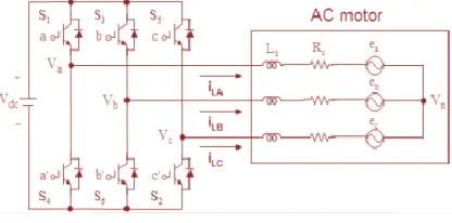
switching inherent to these algorithms. Space vector modulation is a PWM control algorithm for multi‐phase AC generation, in which the reference signal is sampled regularly, after each sample, non‐zero active switching vectors adjacent to the reference vector and one or more of the zero switching vectors are selected for the appropriate fraction of the sampling period in order to synthesize the reference signal as the average of the used vectors. The circuit model of a typical three‐phase voltage source PWM inverter is shown in Fig. 1, S1 to S6 are the six power switches that shape the output, which are controlled by the switching variables a, a′, b, b′, c and c′. When an upper IGBT is switched on, i.e., when a, b or c is 1, the corresponding lower IGBT is switched off, i.e., the corresponding a′, b′ or c′ is 0.
Fig.1 Three‐phase voltage source PWM Inverter
In electric automobile applications, pm synchronous driven using field-oriented control . This technique is applied in a synchronous rotating 0–d–q frame to get dc quantities that can be regulated without a steady-state error by simple proportional–integral correctors. The generic self-control diagram that is implemented in this paper. The control loop purpose is to force theidandi0currents to zero and to meet the torque demand using only iq current
III. SIMULATION RESULTS
The main aim of any modulation technique is to obtain variable output having maximum fundamental component with minimum harmonics. The objective
of Pulse Width Modulation techniques is
enhancement of fundamental output voltage and reduction of harmonic content in Three Phase Voltage Source Inverters. In this paper Space Vector PWM techniques for different levels are compared in terms of Total Harmonic Distortion (THD). A
Simulation of SVPWM Space vector PWM is an advanced technique used for variable frequency drive applications. It utilizes dc bus voltage more effectively and generates less THD in the Three Phase Cascaded H bridge inverter. SVPWM utilize a chaotic changing switching frequency to spread the harmonics continuously to a wide band area so that the peak harmonics can be reduced greatly. Simulation has been carried out by varying the
modulation index between 0and 1. Finally
performance of SVPWM is improved in fivel level with 12 sector when compared to three level inverter with 6 sector. The Block Diagram of Space Vector Pulse width modulated inverter fed RL load is shown in Fig.2. In SVPWM methods, the voltage reference is provided using a revolving reference vector. In this case magnitude and frequency of the fundamental component in the line side are controlled by the magnitude and frequency, respectively, of the reference voltage vector. Space vector modulation utilizes dc bus voltage more efficiently and generates less harmonic distortion in a three phase voltage source inverter and multi level inverter
Fig 2.Simulink block diagram of three level Cascaded H Bridge Inverter
Fig. 4. SVPWM methods comparison in self-control mode.
IV. CONCLUSION
The objective of the Fuzzy based (SVPWM) Space vector Modulation Technique has turn out to be the most prevalent and imperative PWM technique for Three Phase Voltage Source Inverters for the control of AC Induction Brushless DC Switched Reluctance
and Permanent Magnet Synchronous Motors
(PMSM). This paper first familiarize the relative analysis of Fuzzy based SVPWM with different sectors is carried out. The model Simulation study reveals that Fuzzy based SVPWM gives 11.58% THD for seven level and 26.4 % for three level cascaded H-bridge inverter enhanced fundamental output with better quality i.e. lesser THD compared to SVPWM. The SVPWM are implemented in MATLAB/SIMULINK software.
REFERENCES
[1] M. Ciappa, “Prediction On The Base Of Mission Profiles,” Microelectron. Reliab., Vol. 45, No. 9–11, Pp. 1293–1298, Sep.–Nov. 2005.
[2] V. Smet, F. Forest, J. Huselstein, F. Richardeau, Z. Khatir, S. Lefebvre, And M. Berkani, “Ageing
And Failure Modes Of Igbt Modules In
Hightemperature Power Cycling,” Ieee Trans. Ind. Electron., Vol. 58, No. 10, Pp. 4931–4941, Oct. 2011.
[3] D. Martineau, T. Mazeaud, M. Legros, C. Ph. Dupuy, And C. Levade, “Characterization Of Alterations On Power Mosfet Devices Under Extreme Electro-Thermal Fatigue,” Microelectron. Reliab., Vol. 50, No. 9–11, Pp. 1768–1772, Sep.– Nov. 2010.
[4] N. Bianchi, S. Bolognani,M. Zigliotto, And M. Zordan, “Innovative Remedial Strategies For Inverter Faults In Ipm Synchronous Motor Drives,” Ieee Trans. Energy Convers., Vol. 18, No. 2, Pp. 306–314, Jun. 2003.
[5] J. Dixon, J. Pereda, C. Castillo, And S. Bosch, “Asymmetrical Multilevel Inverter For Traction Drives Using Only One Dc Supply,” Ieee Trans. Veh. Technol., Vol. 59, No. 8, Pp. 3736–3743, Oct. 2010.
[6] R. Wang And J. Wang, “Fault-Tolerant Control With Active Fault Diagnosis For Four-Wheel Independently Driven Electric Ground Vehicles,” Ieee Trans. Veh. Technol., Vol. 60, No. 9, Pp. 4276– 4287, Nov. 2011.
[7] D. Diallo, M. E. H. Benbouzid, And A. Makouf, “A Fault-Tolerant Control Architecture For Induction Motor Drives In Automotive Applications,”Ieee Trans. Veh. Technol., Vol. 53, No. 6, Pp. 1847–1855, Nov. 2004.
[8] M. E. H. Benbouzid, D. Diallo, And M. Zeraoulia, “Advanced Faulttolerant Control Of Induction-Motor Drives For Ev/Hev Traction Applications: From Conventional To Modern And Intelligent Control Techniques,”Ieee Trans. Veh. Technol., Vol. 56, No. 2, Pp. 519–528, Mar. 2007.
[10] L. De Sousa And B. Bouchez, “Combined Electric Device For Powering Andcharging,” Patent Wo 2010/057 892 A1, May 27, 2010.
[11] L. De-Sousa And B. Bouchez, “Method And
Electric Combined Devicefor Powering And
Charging With Compensation Means,” Int. Patent Wo2010/057 893 A1, May 27, 2010.
[12] L. De Sousa, B. Silvestre, And B. Bouchez, “A Combined Multiphaseelectric Drive And Fast Battery Charger For Electric Vehicles Topology Andelectric Propulsion Efficiency Analysis,” Inconf. Rec. Ieee Vpp, France,Sep. 1–3, 2010, Pp. 1–6.
[13] S. Lacroix, M. Hilairet, And E. Laboure, “Design Of A Battery-Chargercontroller For Electric Vehicle Based On Rst Controller,” Inconf. Rec.Ieee Vppc, Sep. 6–9, 2011, Pp. 1–6.
[14] H. Schwab, A. Klönne, S. Reck, I. Ramesohl, G. Sturtzer, And B. Keith,“Reliability Evaluation Of A Permanent Magnet Synchronous Motor Drivefor An Automotive Application,” Inconf. Rec. Ieee Epe 10th Eur. Conf.,Dec. 2–4, 2003, Pp. 1–10.
[15] L. Dulau, S. Pontarollo, A. Boimond, J.-F. Garnier, N. Giraudo, Ando. Terrasse, “A New Gate Driver Integrated Circuit For Igbt Deviceswith Advanced Protections,”Ieee Trans. Power Electron., Vol. 21, No. 1,Pp. 38–44, Jan. 2006. [16] M. Bouarroudj-Berkani And L. Dupont, “Fatigue Des Composants Électroniques De Puissance-Physique De Défaillance,”Tech.DeL’ingénieur,Vol. 3126, Pp. 1–21, 2010.
[17] M. Bouarroudj, Z. Khatir, J. P. Ousten, L. Dupont, S. Lefebvre, Andf. Badel, “Comparison Of
Stress Distributions And Failure Modes
Duringthermal Cycling And Power Cycling On High Power Igbt Modules,” Inconf. Rec. Ieee Ape Euro. Conf., Sep. 2–5, 2007, Pp. 1–10.
[18] G. Coquery, G. Lefranc, T. Licht, R. Lallemand, N. Seliger, Andh. Berg, “High Temperature Reliability On Automotive Power Modulesverified
By Power Cycling Tests Up To