International Journal of Research (IJR)
e-ISSN: 2348-6848, p- ISSN: 2348-795X Volume 2, Issue 10, October 2015
Available at http://internationaljournalofresearch.org
Available online:http://internationaljournalofresearch.org/ P a g e | 502
Management of Low and High Frequency Components in
Generation and Reduce Fluctuations Fed by DFIG Based WIND
System with Battery and Fuel Cell
1
J.Rajesh Reddy &
2P.Sivakrishna
1 J.Rajesh Reddy, M.Tech, Power Electronics ,Brahmaiah College of Engineering, A.P, India.
Email: [email protected]
2 P.Siva Krishna, Asst.Proff, Brahmaiah College of Engineering, A.P,India.
Email:[email protected]
ABSTRACT
The paper emphasizes on the application of hybrid energy storage systems to mitigate the effect of wind speed fluctuations, thereby ensuring smooth power output as well as improving the power quality at the PCC. To achieve this a control strategy is designed for managing the demand – generation fluctuations using a hybrid energy storage system in a wind dominated remote area power supply system consisting of a DFIG, fuel cell, a super capacitor, a dump load and main loads. Operation of fuel cell is coordinated with a super capacitor with a view to improving the performance of the fuel cell. In this model, the fuel cell storage system is connected to the load side of the RAPS system, whereas the super capacitor is connected to the dc bus of the back – to – back converter of the DFIG. The models are simulated in Matlab/Simulink environment.
1. INTRODUCTION
Electricity is identified as one key commodity which can be used as a medium for economic growth in rural and regional areas. According to ministry of new and renewable energy, country's present installed power generation capacity has more than doubled to 2, 34,600 MW in the past 10 years. Renewable energy contributes to nearly 34351.39 MW to the total generating capacity and in which wind energy contributes 20149.5 MW. Even though we have 20149.5 MW of installed capacity, India faces an outage of more than 30000 MW due to increase in demand. This shortage can be reduced by use of renewable energy, since renewable energy is reliable, abundant and will
potentially be very cheap once the technologyimprove
1.1HYBRID ENERGY STORAGE
SYSTEM
An ideal energy storage in a standalone wind energy conversion system should be able to provide both high energy and power capacities to handle situations such as wind gusts and load step changes, which may exist for seconds or minutes or even longer. At present, various types of storage technologies are available to full fill either power or energy requirements of a RAPS system. Widely used energy storage technologies that currently employ in wind farms are batteries, super capacitors, fly wheels, compressed-air energy storage, hydro pumped storage, superconducting magnetic energy storage, fuel cells, etc.Hybrid energy storage system is a system which consists of a battery and a super capacitor which are comparativel
best when compared other storing
International Journal of Research (IJR)
e-ISSN: 2348-6848, p- ISSN: 2348-795X Volume 2, Issue 10, October 2015
Available at http://internationaljournalofresearch.org
algorithm is designed in such a way that the supercapacitor should be able to absorb the ripple component of demand – generation mismatch leaving the steady component for the battery storage system. In this paper design and development of wind dominated RAPS system to maintain the load side voltage and frequency within acceptable limits during over – generation and under – generation. To achive this main objective, it is important to manage the active and reactive power contribution of the components of the RAPS system. In this regard, control coordinated strategies are developed and implemented among the components present within the RAPS system. In addition, individaul control is developed based on an appropriate coordinated control approach with a view to regulate the magnitude of the voltage and freqency on the load side. In this thesis, RAPS system consisting of battery storage, super capacitor and dump load along with wind turbine generator as the main component are considered.
2. DFIG OPERATION AND
CONTROLLING
2.1 OPERATING OF THE DFIG
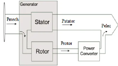
In this thesis, DFIG is given much importance because it feds ac currents into both the startor and the rotot windings. The primary advantage of DFIG when compared to other generators is that when used in wind turbines they allow the amplitude and frequency of their output voltage to be maintained at a constant value, no matter the speed of wind blowing on the wind turbine rotor. A typical configuration of a DFIG based wind turbine generator system is shown in Fig.2.1
Figure 2.1: DFIG based wind turbine generator system
The operation of which can be categorized into two modes: (a) super – synchronous and (b) sub
– synchronous. The difference between operations of these two modes can be determined from the rotor speedωr, compared to the synchronous speedωs, and the direction of power flowing through the back – to – back converter.
In the super – synchronous mode, the rotor speed of the DFIG is kept above synchronous speed leading to a negative slip s < 0, as evident from Eq. (2.1). During the super – synchronous mode, the generated wind power passes to the load through the stator, as well as through the rotor, of the DFIG which is given by Eq.(2.2) and (2.3) respectively (i.e., Pr> 0) as shown in
Fig.2.2
Figure 2.2:Super –synchronous mode of operation
s = ωs−ωr
ωs (2.1)
Ps = Pm
(1−s) (2.2)
Pr = −sPs
(2.3)
In contrast, during the sub – synchronous mode of operation, the rotor speed is kept below the synchronous speed. The generated wind power is supplied to the load by the stator while slip power is absorbed through the rotor (i.e., Pr< 0) as shown in
International Journal of Research (IJR)
e-ISSN: 2348-6848, p- ISSN: 2348-795X Volume 2, Issue 10, October 2015
Available at http://internationaljournalofresearch.org
Figure 2.3:Sub – synchronous mode of operation
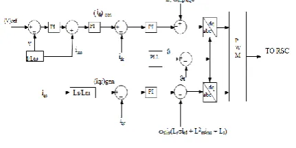
2.2. ROTOR SIDECONVERTERCONTROL
As shown in Fig.3.5, the RSC controller consists of inner – loops which have fast field oriented current control and the slow outer – loops that generate the reference currents forth inner loops.
Figure 2.4: RSC control scheme
ThevoltagecontrolleroftheDFIGisdevelopedusin
gareactivepowerbased control
approach.Inthisregard,thetotalstatorreactivepowe routputQs,ofDFIG givenin Eq. (2.4)
Qs =3
2 − Vs2
ωLs + Vs
Lm
Ls idr
(2.4)
Therotord –
axiscurrentidr,consistsoftwocomponents,namely: magnetizing
current,idrmag,whichismainlyusedformagnetizatio npurposeoftheDFIGand
idrgenwhichisusedtosatisfythereactivepowerrequir ementsoftheloads.The
correspondingreactivepowercomponentsoftheset wocurrents,namely:Qmagand Qgenaregivenby Eq. (2.5)and Eq. (2.6)respectively.
Qmag =
3 2 −
Vs2
ωLs + Vs
Lm
Ls idrmag
(2.5)
Qgen =3
2Vs Lm
Ls idrgen (2.6)
2.3 LINESIDECONVERTERCONTROL
TheLSCisusedtocontroltheDCbusvoltageoftheba
ck – to – backconverter
systemandtosupplyanyreactivepowertotheloadsif needed
Figure 2.5:LSC control scheme
Thedandqaxescomponentsofcurrentsthroughfilte rcanbeused
toregulatetheDClinkvoltageandreactivepowersup plytotheloadsrespectively.
Althoughthereisapossibilityofsupplyingreactivep owerthroughLSCsimilarto
astaticsynchronouscompensator(STATCOM),int hepresentwork,thereactive
powerreferenceQrefissetatzero.Thecorresponding controlschemeimplemented
forLSCisshowninFig.2.5.
Rotor side converter and Line side converter operation was also explained along with their controlling schemes. The controlling implemented is flux oriented vector control andPitch angle controlling
3. PROPOSED MODEL OF RAPS SYSTEM
TheconfigurationoftheDFIGbasedRAPSsystemc onsistingofthehybridenergy
storageanddumploadwithmainloadsisshowninFi g3.1.Thebatterystorageis
connectedtotheloadsideusinganinverterwhereast hesuper capacitorisinterfaced to theDCbus ofthe back – to – backconvertersystem bymeans ofa bi –directional buck boostconverter.
International Journal of Research (IJR)
e-ISSN: 2348-6848, p- ISSN: 2348-795X Volume 2, Issue 10, October 2015
Available at http://internationaljournalofresearch.org
Figure 3.1:Proposed model of DFIG based RAPS
system
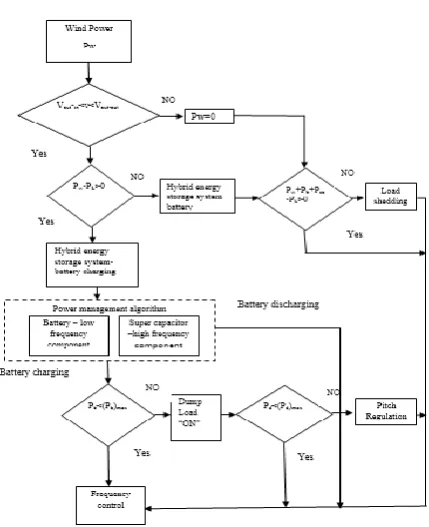
Figure 3.1:A Coordinated control approach for hybrid
energy storage based RAPS system
During over generation condition where the power output from the wind turbine generator Pw is greater then the load demand PL, the hybrid
energy storage Pb(i.e., battery storage and super
capacitor) absorbs the excess power (PW – PL )
and is shared between the battery storage system and super capacitor according to the power management algorithm. If the capacity of the hybrid energy storage system reaches the maximum limit or (Pb) max,the dump load needs
to absorb the excess power. However, if the dump load power Pd reaches its maximum limit
rating (Pd) max, the pitch angle control has to be
activated in order to reduce the power output of the wind turbine generator.
During under generation situations where the power output of the wind turbine generator is less than the load demand, i.e., (PW – PL )< 0, it
is assumed that the hybrid energy storage Pb is
able to supply the required power deficit (PL –
PW).
During emergency situations such as no power output from wind turbine generator due to wind speed being below cut – in level or above cut – out level, a load shedding scheme can be implemented. Moreover, the proposed control coordination concept has been realized by developing the control strategies for each component of the RAPS system.
4.Fuzzy Logic Controller
International Journal of Research (IJR)
e-ISSN: 2348-6848, p- ISSN: 2348-795X Volume 2, Issue 10, October 2015
Available at http://internationaljournalofresearch.org
Fig 4.1 Structure of fuzzy logic controller
Table I Membership function rules
Load voltag e
Load curren t
NL N
M
P PM PB
NL PB PB N
M N M
N L
NM PB PB N
M
P N
L
P P PM N
M N M
P
PM N
M
P N
M N M
P M
PB NL N
M N M
NL N
L
5.SIMULATION MODELS AND RESULTS
5.1 BATTERY AND SUPER CAPACITOR RESULTS
Figure 5.2: Simulation circuit with battery and super capacitor
The simulation model with Battery and super capacitor is designed presented above in fig4.1.
ThesystemresponseoftheDFIGbasedRAPSsyste m with battery and super capacitor as hybrid storage system isshownin belowThe FFT analysis of the battery current is shown to be free from ripples or high – frequency component which is presented in Fig 5.6.The
operating frequency of the RAPS system is
shown in Fig.5.5. The
operatingfrequencyiscloselyregulatedatitsratedv alueof50 Hz and is seen not to be influenced by the wind speed or load step changes. Furthermore, it can be seen that the frequency of the system is maintained with in 0.2%o fit srated value.
Figure 5.3:Wind speed (battery)
ThevoltageonloadsideisshowninFig.4.4which nottobeaffectedby thewindspeedor loadchanges. This proves that the DFIG controllers are able to maintain voltage constant. Theload voltage
ofthesystemstays 1 Pu
(± 2%ofitsratedvalue)throughouttheoperation.
Figure 5.4:Voltage on load side (battery)
International Journal of Research (IJR)
e-ISSN: 2348-6848, p- ISSN: 2348-795X Volume 2, Issue 10, October 2015
Available at http://internationaljournalofresearch.org
Figure 5.6:FFT analysis of the battery system
Figure 4.7:Hybrid energy storage power
4.2 FUEL CELL AND SUPER CAPACITOR RESULTS
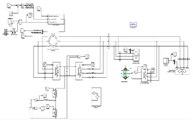
Figure 5.8:Simulation model with fuel cell and super
capacitor
Since fuel cell are more efficient and has life cycle more than batteries, so batteries are replaced by fuel cell. The function of fuel cell is same as that of battery, so controlling is designed same as battery controlling. The simulation model is shown in Fig.4.2
Figure 5.9:Wind Speed (Fuel cell)
Figure 5.10:Voltage on load side (fuel cell)
Figure 5.11:Frequency on load (fuel cell)
Figure 5.12:Hybrid energy storage power
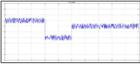
Figure 5.13:Hybrid Energy storage current
TheFuel
cellcurrentconsistsofhighfrequencyfluctuatingco mponentandexhibits
steepDODduringloadstepchanges.Thecurrentlev el of the hybrid energy storage with the super capacitor isshown in Fig.5.13.
Fuelcell and super capacitor responded efficiently depending on increase in demand.
Discrete, Ts = 1e-005 s.
powergui
Generator speed (pu) Pitch angle (deg) Wind speed (m /s) Tm (pu) Wind Turbine v + -v + -g A B C + -Universal Bridge2 g A B C + -g A B C + -Uniform Random Number5 A B C a b c A B C a b
c Aa Bb Cc
A B C a b c A B C a b c PQ m
A B C
Three-Phase Dynamic Load1 PQ m A B C Three-Phase Dynamic Load Saturation1 1/z Rate Transition5 Rate Limiter g m C E g m C E Vdc Goto5 Wind Goto26 theta Goto24 Pd Vuc Goto14 Iuc Goto11 Ib Goto1 vw Goto 40 Gain14 m + -m + -Fuel Cell Stack RSC From9 vw From40 vw From39 battery From26 Pdump From25 D2 From22 D1 From21 LSC From20 Discrete Timer1 Discrete Timer i + -i + -1.5 Constant5 Tm m A B C a b c Asynchronous Machine pu Units Add7
International Journal of Research (IJR)
e-ISSN: 2348-6848, p- ISSN: 2348-795X Volume 2, Issue 10, October 2015
Available at http://internationaljournalofresearch.org
5. CONCLUSION
The paper has addressed the benefits of integrating a super capacitor to a battery storage system in a wind – based hybrid RAPS system. Through simulation studies it can be concluded that RAPS systems was capable in maintaining the constant voltage and frequency at the load end. Also, it has been noted that the power sharing between the systems components were accomplished in accordance with the proposed
coordinated control methodology.
When considering the operation of battery storage systems, avoidance of heavy DOD rates and reduced ripple content in the battery current is given importance. To solve above problem, a super capacitor was integrated with the battery storage system to form the hybrid energy storage (i.e. battery and super capacitor) and improving battery’s performance. Furthermore, it has also been noted that the super capacitors integrated to the DFIG was able to handle the transients caused by wind speed and load changes effectively.
Thus concluding by saying that the hybrid operation of the RAPS systems were capable in maintaining the voltage and frequency at the load end with proper power sharing between the devices
As extensions to the work presented in this paper, following is a description of further activities that can be undertaken in relation to standalone RAPS system:
Development of the control strategies for each component of RAPS systems with a view to operate them under unbalanced load conditions.
Providing protection to the system.
Integration of other types of renewable energy systems (e.g. solar photovoltaic) to wind based RAPS systems.
Further development of the existing control strategies of the RAPS systems to operate as a grid interactive micro – grid.
REFERENCES
[1] N. Mendis, K. M. Muttaqi “Management of Low- and High-Frequency Power Components in Demand-Generation Fluctuations of a DFIG-Based Wind-Dominated RAPS System Using Hybrid Energy Storage,” IEEE Transactions on Industry Applications, Vol. 50, No. 3, May/June 2014.
[2]Doubly fed induction generator system for wind turbine by S. MÜLLER, M. DEICKE, & RIK W. DE DONCKER May/June 2011.
[3] P. F. Ribeiro, B. K. Johnson, M. L. Crow, A. Arsoy, and Y. Liu, “Energy storage systems for advanced power applications,” Proc. IEEE, vol. 89, no. 12, pp. 1744–1756, Dec. 2001.
[4]M.Beaudin, H.Zareipour,A.Schellenberglabe, and W.Rosehart,“Energy storage for mitigating the variability of renewable electricity sources: An updated review,” Energy Sustainable Develop., vol. 14, no. 4, pp. 302– 314, Dec. 2010.
[5] T. Patrick and Moseley, “Energy storage in remote area power supply(RAPS) systems, “J.PowerSources, vol.155, no.1, pp.83–87, Apr.2006.
[6] W. Li, G. Joos, and J. Belanger, “Real-time simulation of a wind turbine generator coupled with a battery super capacitor energy storage system,” IEEE Trans. Ind. Electron., vol. 57, no. 4, pp. 1137–1145, Apr. 2010.
[7] P. Thounthong, S. Rael, and B. Davat, “Control strategy of fuel cell and supercapacitors association for a distributed generation system,” IEEE Trans. Ind. Electron., vol. 54, no. 6, pp. 3225–3233, Dec. 2007.
[8]S. Bhattacharyya (ed.), Rural Electrification through Decentralized Off-grid Systems in Developing Countries, Green Energy and Technology, DOI: 10.1007/978-1-4471-4673-5_2, Springer-Verlag London 2013.
[9] John Fletcher and Jin Yang (2010). Introduction to the Doubly-Fed Induction Generator for Wind Power Applications, Paths to Sustainable Energy, Dr Artie Ng (Ed.), ISBN: 978-953-307-401-6, Intec, Available from:
International Journal of Research (IJR)
e-ISSN: 2348-6848, p- ISSN: 2348-795X Volume 2, Issue 10, October 2015
Available at http://internationaljournalofresearch.org
sustainable-energy/introduction-to-the-doubly- fed-inductiongenerator-for-wind-power-applications
[10] Literature review paper on doubly fed induction generator wind turbine technology Ajay Kushwaha1, Inderpreet Singh2 1,2EIED, Thapar University, Patiala, Punjab, IndiaISSN: 2319-7463 Vol. 2 Issue 9, September-2013.
[11] D. Santos-Martin, S. Arnaltes, and J. L. R. Amenedo. Reactive power capability of doubly fed asynchronous generators. Journal of Electric Power Systems Research, 78(11):1837 – 1840, Nov. 2008.
[12] KrisztinaLeban. Doubly Fed Induction Generator Fault Simulations.PhD thesis, Institute of Energy Technology, Aalborg University, Alborg, Denmark, 2009.
[13] R. Pena, J. C. Clare, and G. M. Asher.Doubly fed induction generator using back – to – back PWM converters and its application to variable – speed wind – energy generation. IEE Proceedings - Electric Power Applications, 143(3):231 – 241,May 1996.
Mr. JETTY RAJESH REDDY was born in India in the year of 1990. He received B. Tech degree in Electrical and Electronics Engineering in the year 2013 (AUDISANKARA COLLEGE OF ENGINEERING AND TECHNOLOGY , JNTUA) IN NELLORE . and PURSUING M. Tech in Power Electronics EEE Department from Brahmaiah College of Engineering,
A.P, India,
MAIL ID: [email protected]
P.SIVA KRISHNA received his B.Tech Degree in Electrical and Electronics Engineering from Narayana engineering college, Nellore affilated to jntuananthapur. He received his M.Tech from sreevenkataperumalu engineering college puttur,chitter dist. He has 1 years teaching experience, presently working as Asst.Professor of EEE, Brahmaiahcollegeof engineering Affiliated to JNTU, Anantpur. Andhra Pradesh, India.