Available online:
http://edupediapublications.org/journals/index.php/IJR/
P a g e | 1166An Experimental study on the effect of welding
parameters and tool pin profile on AA 6061 and
AA 7175 Friction stir welded butt joint
1
Patlolla Satish Kumar, Pursuing M.Tech (Manufacturing Technology),
2
Mrs.K.Malleswari, Assistant Professor, M.Tech (NIT-Trichy)
3
Dr.Punna Eshwaraiah, Professor, M.Tech, Ph.D. (IIT Delhi)
1, 2, 3
Mechanical Department, GITAM UNIVERSITY, HYDERABAD.
Abstract:
Friction stir welding (FSW) is a novel solid state welding process for joining metallic alloys and has emerged as an alternative technology used in high strength alloys that are difficult to join with conventional techniques and which avoids bulk melting of the basic material, hot cracking and porosity. The function of FSW process are used in
several industries such as aerospace, rail,
automotive and marine industries for joining aluminium, magnesium and copper alloy. In aerospace industries most of the component is manufactured with aluminium material by welding process. Aluminium welding cannot be done by conventional process because temper characteristics of material will be changed. To overcome this drawback, friction stir welding process is selected. To investigate the effect of welding parameters and different tool pin profiles over Friction Stir Welding of dissimilar AA 6061 and AA 7175 and also compare single pass friction stir welding and multi pass friction stir welding. The parameters considered were tool rotation speed, welding speed, tool pin profiles, tilt angle and number of passes. Different tool pin profiles are Threaded Triangular, Threaded Cylindrical, Threaded Hexagonal and Threaded Taper pin profiles plays a vital responsibility in deciding the weld quality. This work includes tensile tests, hardness test and impact test. .
Keywords
Systems-on-Chip (SoC), high definition (HD) video and ultra-high definition video, DSP, HEVC video coding, VLSI, SDRAM, SRAM, Chroma Filtering,
1.
Introduction
A variety of joining processes for metal parts have been employed in various fields of the manufacturing industry. Depending on the types or
combinations of energy, metal welding processes may be divided into two major groups: (1) fusion welding and (2) solid-state welding. Fusion welding processes use intense localized heat source to melt the base metal. Solid-state welding is completed under pressure alone or a combination of heat and pressure. If heat is used, the temperature in the solid-state welding process is below the melting temperature.
Friction Stir Welding (FSW) falls in the category of solid state welding which was invented by The Welding Institute (TWI) in 1991 for joining low melting temperature alloys like aluminum, magnesium and copper (Thomas et al. 1991). The basic principle of FSW involves plunging a spinning tool that has a specially designed pin and shoulder into the work pieces that are intended for welding. Since melting of materials is avoided, FSW avoids problems such as distortion and metallurgical reactions which typically appear in conventional fusion welding processes. It is reported that the strength of the FSW weld is 30% to 50% greater than those produced by arc welding and resistance spot welding while maintaining the fatigue life comparable to riveted panels (Mendez and Eagar 2001).
Available online:
http://edupediapublications.org/journals/index.php/IJR/
P a g e | 1167Friction stir welding is used already in routine, as well as critical applications, because it produces strong and ductile joints. The process is most suitable for components which are flat and long (plates and sheets) but also it can be used for pipes, hollow sections, and positional welding.
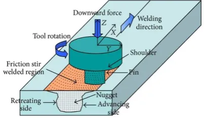
Figure 1: Schematic diagram of friction stir welding Friction stir welding (FSW) is a novel solid state welding process for joining metallic alloys and has emerged as an alternative technology used in high strength alloys that are difficult to join with conventional techniques that uses a third body tool to join two facing surfaces. In particular cases, it can be used to join high strength alloys or other metallic alloys which are hard to weld by conventional fusion welding. Heat is generated between the tool and material which leads to a very soft region near the FSW tool. It then mechanically intermixes the two pieces of metal at the place of the joint, then the softened metal (due to the elevated temperature) can be joined using mechanical pressure (which is applied by the tool), much like joining clay, or dough. It is primarily used on aluminum, and most often on extruded aluminum (non-heat treatable alloys), and on structures which need superior weld strength without a post weld heat treatment and which avoids bulk melting of the basic material, hot cracking and porosity . The applications of FSW process are found in several industries such as aerospace, rail, automotive and marine industries for joining aluminum, magnesium and copper alloys. This material has gathered wide acceptance in the fabrication of light weight structures requiring a high strength-to-weight ratio.
2.
Design Constraints
A. Problem Statement
For FSW, two parameters are very important: tool rotation rate (ω, rpm) in clockwise or counterclockwise direction and tool traverse speed (v, mm/min) along the line of joint. The rotation of tool results in stirring and mixing of material around the rotating pin and the translation of tool moves the stirred material from the front to the back of the pin
and finishes welding process. Higher tool rotation rates generate higher temperature because of higher friction heating and result in or intense stirring and mixing of material. However, it should be noted that frictional coupling of tool surface with work piece is going to govern the heating. So, a monotonic increase in heating with increasing tool rotation rate is not expected as the coefficient of friction at interface will change with increasing tool rotation rate.
B. Aim of the Project and Design Goals
Although significant efforts have been made in the recent past to develop cost effective and reusable tools, most of the efforts have been empirical in nature and further work is needed for improvement in tool design to advance the practice of FSW to hard alloys. It is a well-known fact that different types of tools can be used for friction stir welding like polycrystalline cubic boron nitride tools, tool steels, tungsten based tools, hot worked tools etc. But for our investigation purpose we are considering H13 tool because of its superior strength.
Chromium hot worked tool steels are classified as group H steels by the AISI classification system. This series of steels from H1 to H19. H13 chromium hot work steel is widely used in hot and cold work tooling applications. Due to its excellent combination of high toughness and fatigue resistance H13 is used more than any other tool steel in tooling applications. H-13 is a chromium, molybdenum, vanadium hot work tool steel which is characterized by high hardenability and excellent toughness. The molybdenum and vanadium act as strengthening agents. The chromium content assists H-13 to resist softening when used at high temperatures. H-13 offers an excellent combination of shock and abrasion resistance, and possesses good red hardness. It is capable of withstanding rapid cooling and resists premature heat checking. H-13 has good machinability, good weld ability, good ductility, and can be formed by conventional means.
Available online:
http://edupediapublications.org/journals/index.php/IJR/
P a g e | 1168(through hardening in large section thicknesses) and better wear resistance than common alloy steels.
3.
Design and Implementation
For the purpose of our experimental investigation, we are considering friction stir on dissimilar aluminum alloys 6061 &7175.Single & Multi pass Friction Stir Welding of the alloys was also compare single pass friction stir welding and multi pass friction stir welding. The parameters considered were tool rotation speed, welding speed, tool pin profiles, tilt angle and number of passes. Different tool pin profiles are Threaded Triangular, Threaded Cylindrical, Threaded Hexagonal and Threaded Taper pin profiles plays a vital responsibility in deciding the weld quality. This work includes tensile tests, hardness test and impact test. After performing all the mechanical tests the properties of respective welded alloys are compared with each other based on the changing parameter in each weld.
A.
Single pass welding
In single pass Friction Stir Welding the number of passes is one the parameters considered were tool rotation speed is 1120 rpm, welding speed is 40 mm/min, and tilt angle is 0°. For our investigation, we have taken Threaded Triangular, Threaded Cylindrical, Threaded Hexagonal and
Threaded Taper tool pin profiles. After performing all the mechanical tests the properties of respective welded alloys are compared with multi pass welding.
B.
Multi pass welding
In multi pass Friction Stir Welding the number of passes is two the parameters considered same as single pass welding it is easy to compare the both welds, tool rotation speed is 1120 rpm, welding speed is 40 mm/min, and tilt angle is 0°. For our investigation, we have taken Threaded
Triangular, Threaded Cylindrical, Threaded Hexagonal and Threaded Taper tool pin profiles. After performing all the mechanical tests the properties of respective welded alloys are compared with single & multi pass welding.
C.
Tool Design
For our investigation, we have taken Threaded Triangular, Threaded Cylindrical, Threaded Hexagonal and Threaded Taper tool pin profiles. It is desirable that the tool material is sufficiently strong, tough, and hard wearing at the welding temperature.
Further it should have a good oxidation resistance and a low thermal conductivity to minimize heat loss and thermal damage to the machinery further up the drive train. Hot-worked tool steel such as AISI H13 has proven perfectly acceptable for welding aluminum alloys within thickness ranges of 0.5 – 50 mm but more advanced tool materials are necessary for more demanding applications such as highly abrasive metal matrix composites or higher melting point materials such as steel or titanium.
Improvements in tool design have been shown to cause substantial improvements in productivity and quality. TWI has developed tools specifically designed to increase the penetration depth and thus increasing the plate thicknesses that can be successfully welded. An example is the "whorl" design that uses a tapered pin with re-entrant features or a variable pitch thread to improve the downwards flow of material. The majority of tools have a concave shoulder profile which acts as an escape volume for the material displaced by the pin, prevents material from extruding out of the sides of the shoulder and maintains downwards pressure and hence good forging of the material behind the tool.
D.
Feed Rate
Feed rate is the relative velocity at which the cutter is advanced along the work piece, its vector is perpendicular to the vector of cutting speed. Feed rate units depend on the motion of the tool and work piece when the work piece rotates, the units are almost always distance per spindle revolution or mm per minute. A feed rate of 40 mm per minutes is maintained throughout the welding process.
E.
Tool Rotation
It is obvious that the rotating speed is one of the main factors affecting the frictional heat. If the rotating speed is too low, the frictional heat is not enough to induce plasticized flow, the metal in the weld cannot diffuse and recrystallize, and there are holes in the weld. Along with an increase of the rotating speed, the frictional heat increases, the plasticized layer increase from top to the underside, the holes in the weld become smaller. When the rotating speed reaches a certain number, the holes in the weld becomes tightness. But if the rotating speed is too high, the temperature of materials beneath the tool's shoulder and around the probe will excess the melt point, and the weld is no long a solid-state joint. In our investigation, tool rotation speed is maintained as 1120rpm throughout.
Available online:
http://edupediapublications.org/journals/index.php/IJR/
P a g e | 1169It is the angle with which the tool pin is inclined to the work piece. Generally, it varies depending upon the type of joint which has to be produced. In the investigation which we are carrying involves producing butt joints. So for producing butt joints the tilt angle is maintained as 0 degrees throughout the welding process.
Figure 2: Schematic diagram of practical arrangement of a fixture
Fig 3: Experimental work of Friction Stir Single & Multi pass welding
4.
Results and Discussion
Izod Impact Test
Izod impact testing is an ASTM standard method of determining the impact resistance of materials. An arm held at a specific height (constant potential energy) is released. The arm hits the sample.The specimen either breaks or the weight rests on the specimen. From the energy absorbed by the sample, its impact energy is determined. A notched sample is generally used to determine impact energy and notch sensitivity.
The test is similar to the Charpy impact test but uses a different arrangement of the specimen under test. The Izod impact test differs from the Charpy impact test in that the sample is held in a cantilevered beam configuration as opposed to a three-point bending configuration.
Impact is a very important phenomenon in governing the life of a structure. For example, in the case of an aircraft, impact can take place by a bird hitting a plane while it is cruising, or during take-off and landing the aircraft may be struck by debris that is present on the runway, and as well as other causes. It must also be calculated for roads if speed breakers are present, in bridge construction where vehicles punch an impact load, etc.
Impact tests are used in studying the toughness of material. A material's toughness is a factor of its ability to absorb energy during plastic deformation. Brittle materials have low toughness as a result of the small amount of plastic deformation that they can endure. The impact value of a material can also change with temperature. Generally, at lower temperatures, the impact energy of a material is decreased. The size of the specimen may also affect the value of the Izod impact test because it may allow a different number of imperfections in the material, which can act as stress risers and lower the impact energy.
Charpy’s Impact Test
Available online:
http://edupediapublications.org/journals/index.php/IJR/
P a g e | 1170amount of energy when impact tested, a tough ductile metal absorbs a large amount of energy. The appearance of a fracture surface also gives information about the type of fracture that has occurred; a brittle fracture is bright and crystalline, a ductile fracture is dull and fibrous.
The apparatus consists of a pendulum of known mass and length that is dropped from a known height to impact a notched specimen of material. The energy transferred to the material can be inferred by comparing the difference in the height of the hammer before and after the fracture (energy absorbed by the fracture event).
The notch in the sample affects the results of the impact test, thus it is necessary for the notch to be of regular dimensions and geometry. The size of the sample can also affect results, since the dimensions determine whether or not the material is in plane strain. This difference can greatly affect conclusions made.
Brinell’s Hardness Test
Dr J. A. Brinell invented the Brinell test in Sweden in 1900. The oldest of the hardness test methods in common use today, the Brinell test is frequently used to determine the hardness of forgings and castings that have a grain structure too course for Rockwell or Vickers testing. Therefore, Brinell tests are frequently done on large parts. By varying the test force and ball size, nearly all metals can be tested using a Brinell test. The Brinell scale characterizes the indentation hardness of materials through the scale of penetration of an indenter, loaded on a material test-piece.
The test uses a 5 millimetres diameter of ball as an indenter with a 250kgf force. For softer materials, a smaller force is used; for harder materials, a tungsten carbide ball is substituted for the steel ball. For our investigation, we have applied a load of 250kgf and used 5mm diameter ball and the weld hardness is tested for work pieces which are made of Threaded Triangular, Threaded Cylindrical, Threaded Hexagonal, and Threaded Taper pin profiles and these values are compared. The below table shows the results which are obtained and it is observed that hardness is more for the weld which is made out of Threaded Triangular tool pin profile.
Ultimate Tensile Strength Test
Ultimate tensile strength (UTS) often shortened to tensile strength (TS) or ultimate strength, is the maximum stress that a material can withstand while being stretched or pulled before failing or breaking. Tensile strength is distinct from compressive strength. Some materials break sharply, without plastic deformation, in what is called a brittle failure
others, which are more ductile, including most metals, experience some plastic deformation and possibly necking before fracture.
A universal testing machine (UTM), also known as a universal tester, materials testing machine or materials test frame, is used to test the tensile strength and compressive strength of materials. It is named after the fact that it can perform many standard tensile and compression tests on materials, components, and structures.
Considering our experiment ultimate load, ultimate yield strength, elongation, ultimate tensile strength are found out and are compared for both the welds which are performed by using cylindrical threaded and triangular threaded pin profiles on an UTM machine.
5.
Conclusion and Future Scope
The Friction stir welding, tool pin profile and number of passes are influenced the weld quality. From this project work, it is inferred that the rotational speed of 1120 rpm, traverse speed of 40mm/min, and tool tilt angle 0°.
• The impact strength for Izod test, multi pass weld made by threaded hexagonal tool pin is the highest i.e. is 0.5 J/mm2 among all the single & multi pass welding.
• The impact strength for Charpy’s test, multi pass weld made by threaded hexagonal tool pin is the highest i.e. is 1.15 J/mm2 among all the single & multi pass welding.
• The hardness is found to be increasing in Multi pass Friction stir welding in threaded triangular i.e. 159.15 Kgf/mm2 when compared to the other types of tool pin profiles.
• The Ultimate tensile strength for Multi pass welding the threaded Hexagonal tool pin profile has more tensile strength i.e. 218.240 N/mm2 when compared to the other types of tool pin profiles.
• The elongation for Single pass welding the threaded taper tool pin profile has more elongation i.e. 2.64 % when compared to the other types of tool pin profiles.
• The yield strength for Multi pass welding the threaded cylindrical tool pin profile has more yield strength i.e. 178.143 N/mm2 when compared to the other types of tool pin profiles.
Available online:
http://edupediapublications.org/journals/index.php/IJR/
P a g e | 11716.
References
1) Effect of welding parameters on friction stir welded dissimilar aluminum alloys 7075 and 6082 with various tool pin profiles, International conference on recent advancement in mechanical engineering &technology (ICRAMET’ 15), issue 9: April 2015.
2) Effect of FSW Multi pass on Microstructure and Impact Strength of AL6063, American International Journal of Research in Science, Technology, and Engineering & Mathematics (AIJRSTEM) - 2014.
3) The influences of multi-pass friction stir processing on the microstructural and mechanical properties of Aluminum alloy 6082’, in the journal of Material processing technology, Vol 212, PP 1157-1168
4) https://en.wikipedia.org/wiki/Friction_stir_weld ing.
5) http://www.makeitfrom.com/material-properties/6061-T6-Aluminum/
6) http://www.sciencedirect.com/science/article/pi i/S1877705813018067
7) http://www.suppliersonline.com/propertypages/ 7175.asp
8) http://www.hudsontoolsteel.com/technical-data/steelH3