ANALYSIS OF PYRAMID EM WAVE ABSORBER BY FDTD METHOD AND COMPARING WITH
CAPACITANCE AND HOMOGENIZATION METHODS
A. Khajehpour and S. A. Mirtaheri
Department of Electrical Engineering K.N.Toosi University of Technology P. O. Box 16315-1355, Tehran, Iran
Abstract—In this paper, we model an array of pyramid electromag-netic wave absorbers and calculate the return loss of this array using the FDTD method. For modeling the frequency dependent of the ab-sorber, the Debye model is used. In doing so, a 3×3structure of nine pyramid absorber is chosen instead of the array. The results are compared with capacitance and homogenization methods using aver-age values for ε [10]. The results clearly show that the FDTD is an accurate method for calculating the return loss of an array of pyramid absorbers as compared with three other existing methods, and can be used to simulate the array of pyramid absorbers with different sizes in a wide range of frequencies.
1. INTRODUCTION
There are different structures for EM wave absorbers, such as wedge [1], pyramid [2] and honeycomb [3] used in anechoic chambers for reflectivity measurements [4–7]. In this paper we obtain the reflection of pyramid absorbers over the frequency range of 100–1000 MHz. To simulate pyramid absorbers, different models such as the capacitance model [8], the transmission line [4] and the homogenization method are used [9–11].
2. FDTD METHOD FOR DISPERSIVE MEDIA
Numerical and semi-analytic methods for simulating electromagnetic wave absorbers use integral equations based on the MOM, the FEM, and the FDTD [13–16]. The FDTD is a time-domain technique that directly calculates the impulse response of an EM system. It can also be used for non-homogenization materials, because ε, µ and σ can be defined for each point of the area separately, and the results of the frequency-domain are calculated from the results of time-domain analysis.
3. MODELING THE PYRAMIDAL ABSORBER
In order to use the FDTD method, frequency dependence of ε and µ must be taken into account [17–23]. The standard procedure is using the convolution-integral approach. This approach becomes very complicated when incorporating the effective properties of a tapered structure. By using the concept of electric and magnetic susceptibility and the Debye model for the frequency dependence, the FDTD method can be modified to eliminate the need for using the convolution-integral approach. This scheme is described below.
The Debye media is characterized by a complex-valued, frequency-domain susceptibility function xp(w) that has one or more real poles
at separate frequencies. For a single-pole Debye medium, we have xp(w) =
εsp−ε∞p
1 +jwτp
= ∆εp 1 +jwτp
(1) where εsp is the static or zero-frequency relative permittivity, ε∞p
is the relative permittivity at infinite frequency and τp is the pole
relaxation time. The real-valued time-domain susceptibility function x(t) is obtained by taking the inverse Fourier transformation of (1), which yields the following decaying exponential function
xp(t) =
∆εp
τp
e−t/τpU(t) (2)
whereU(t) is the unit step. For a Debye medium having P poles, we extend (1) to express the relative permittivity by
ε(w) =ε∞+
p
p=1
1 + ∆εp 1 +jwτp
3.1. Formulation for Multiple Debye Poles by ADE (Auxiliary Differential Equation)
Consider a multi term Debye dispersive medium having a total of P poles in its susceptibility response. At any particular E-field observation point, the Ampere’s law in the time domain for this medium is
∇ ×H(t) = ε0ε∞d dt E(t) + p p=1
Jp(t) (4)
whereJp(t) is the polarization current associated with thePth Debye
pole. The goal of the ADE method is to develop a simple time-stepping scheme forJp(t) which can be updated synchronously by (4). By using
(2), a phasor polarization current is associated with each pole, which is:
Jp(w) =ε0∆εp
jw 1 +jwτp
E(t) (5)
or
Jp(w) +jwτpJp(w) =ε0∆εpjw E(t) (6)
After using the inverse Fourier transform, implementing it in an FDTD code and solving the result forJpn+1 , we obtain
Jpn+1 =kpJpn+βp
En+1−En
∆t
(7) where
kp =
1− ∆t 2τp
1 + ∆t 2τp
(8a)
βp =
ε0∆εp∆t
τp
1 + ∆t 2τp
(8b)
The second component of the ADE algorithm involves obtaining the
En+1. This requires knowledge ofJpn+1/2 , which can be obtained from
(7) Jpn+1/2 =
1 2
Jn
p +Jpn+1
= 1
2
(1 +kp)Jpn+
βp
∆t
To evaluate (4) at time-stepn+ 1/2, we have
∇ ×Hn+1/2 = ε 0ε∞
En+1−En
∆t +σ
En+1−En
2 +1 2 p p=1
(1 +kp)Jpn+
βp
∆t
En+1−En (10)
Using all corresponding terms, we obtain the following explicit time-stepping relation for the E-field
En+1 =
2ε0ε∞+ p
p=1
βp−σ∆t
2ε0ε∞+ p
p=1
βp+σ∆t
En+
2∆t 2ε0ε∞+
p
p=1
βp+σ∆t
×∇ ×Hn+1/2 − p
p=1
(1 +kp)Jpn (11)
Thus, the ADE-FDTD algorithm for modeling a dispersive medium withP Debye poles is a three-step procedure.
3.2. Yee Algorithm
Numerical stability of the Yee algorithm [24] requires bounding of the time-step ∆t relative to the space increments ∆x, ∆y and ∆z. This Courant stability bound is given in three dimensions by
∆t≤ 1 c ·
1
1 ∆x2 +
1 ∆y2 +
1 ∆z2
(12)
The limit on ∆tset by (12) enables successful application of the FDTD method to a wide variety of three-dimensional electromagnetic-wave-modeling problems of moderate electrical size and quality factor.
Note that the Yee cell size must be smaller than the minimum λ for each case, which in this case is 101 λmax. We use (13) to calculate
cell size of the Yee lattice.
∆x,∆y,∆z c K√εrfmax
where fmax is the maximum frequency used in each case, εr is the
complex permittivity of the media andK is the accuracy coefficient of cells in Yee lattice.
In this study we used perfectly matched layers as the absorbing boundary condition in FDTD method.
3.3. Performance with FDTD Method
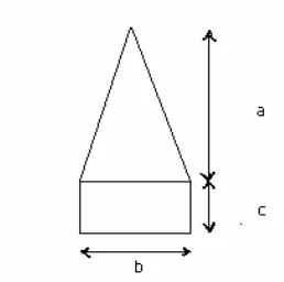
The values ofa,b and c(Fig. 1) for the FDTD method on a pyramid absorbers are 90, 33 and 21 cm, respectively [6].
Figure 1. Electromagnetic wave pyramidal absorber.
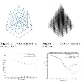
To check the effect of adjacent pyramids in an array of pyramid absorbers (Fig. 2), 9 pyramids are considered in the PML space.
The pyramids are divided into cells taking into account these sizes in the FDTD method (Fig. 3). Each of these nine pyramids suffers from a frequency-dependent dielectric loss. Using the values of dielectric losses in the FDTD method and running the program, we obtain the reflection curve of the array.
4. SIMULATION RESULTS
Figure 2. Nine pyramid ab-sorbers (3×3).
Figure 3. Cellular pyramid absorber.
Figure 4. Real and imaginary parts of permittivity of pyramid absorber.
Figure 5. Return loss of pyra-mid absorber by FDTD method in comparison with the capac-itance and the homogenization methods.
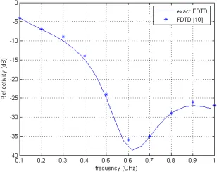
As shown in these figures, the FDTD method is in good agreement with the homogenization method. However, due to the model’s approximation, the capacitance method has conformity at lower frequencies only.
(a) (b)
Figure 6. (a) Real and imaginary parts of permittivity of pyramid absorber; (b) Return loss of the pyramid absorber by the FDTD method as compared to those of the capacitance and homogenization methods.
Figure 7. Return loss of a pyramid absorber by FDTD method as compared [10].
5. CONCLUSIONS
In this paper, the return loss of pyramid absorbers in an array structures for the 3D space by the FDTD method was obtained. By decreasing the cell size in the absorber, the accuracy of measurements will increase. The most suitable dimensions for cells in the above frequency band is 3cm.
ACKNOWLEDGMENT
This work was supported in part by Iran Telecommunications Research Center (ITRC).
REFERENCES
1. Chambers, B., “Characteristics of radar absorbers with tapered thickness,” IEEE Conf. Antennas and Propagation, Apr. 1999. 2. Miyazaki, Y. and K. Tanoue, “Tapered and graded index type
electromagnetic absorbers using inhomogeneous loss dielectric layer,”EMC’89, Vol. 2, Nagoya, Japan, Sept. 1989.
3. Smith, F. C., “Effective permittivity of dielectric honeycombs,”
IEEE Proc. Microw. Antennas and Propagation, Vol. 146, No. 1,
Feb. 1999.
4. Park, M. J., J. Choi, and S. S. Kim, “Wide bandwidth pyramidal absorbers of granular ferrite and carbonyl iron powders,” IEEE
Trans. Magnetics, Vol. 36, No. 5, Sep. 2000.
5. Emerson, W. H., “Electromagnetic absorbers and anechoic chambers through the years,” IEEE Trans. Antennas and
Propagation, Vol. 21, No. 4, July 1973.
6. Chung, B.-K. and H.-T. Chuah, “Modeling of RF absorber for application in the design of anechoic chamber,” Progress In
Electromagnetics Research, PIER 43, 273–285, 2003.
7. Marquart, N. P., “Experimental anechoic chamber measurements of a target near an interface,” Progress In Electromagnetics
Research, PIER 61, 143–158, 2006.
8. Anzai, H., Y. Noito, and T. Mizumoto, “Analysis of pyramid EM wave absorber,” Technical Report of IEICE, EMCJ 94-27, Sept. 1994.
9. Kuester, E. F. and C. L. Holloway, “A low frequency model for wedge or pyramid absorber array — I: Theory,” IEEE Trans.
Electromag. Compat., Vol. 36, 300–306, Nov. 1994.
10. Kuester, E. F. and C. L. Holloway, “A low frequency model for wedge or pyramid absorber array — II: Computed and measured,”
IEEE Trans. Electromag. Compat., Vol. 36, 307–313, Nov. 1994.
12. Toflove, A.,Computational Electrodynamics, the Finite Difference
Time Domain Method, Artech House, Norwood, MA, 1995.
13. Holloway, C. L., P. M. McKenna, R. A. Dalke, R. A. Perala, and C. L. Devor, “Time-domain modeling, characterization and measurements of anechoic and semi-anechoic electromagnetic test chambers,”IEEE Trans. Electromag. Compat., Vol. 44, No. 1, Feb. 2002
14. Hu, X.-J. and D. -B. Ge, “Study on conformal FDTD for electromagnetic scattering by targets with thin coating,”Progress
In Electromagnetics Research, PIER 79, 305–319, 2008.
15. Zainud-Deen, S. H., A. Z. Botros, and M. S. Ibrahim, “Scattering from bodies coated with metamaterial using FDTD method,”
Progress In Electromagnetics Research B, Vol. 2, 279–290, 2008.
16. Gong, Z. Q. and G. Q. Zhu, “FDTD analysis of an anisotropically coated missile,”Progress In Electromagnetics Research, PIER 64, 69–80, 2006.
17. Hillion, P., “Electromagnetic pulse propagation in dispersive media,” Progress In Electromagnetics Research, PIER 35, 299– 314, 2002.
18. Kumar, A. and S. Sharma, “Measurement of dielectric constant and loss factor of the dielectric material at microwave requencies,”
Progress In Electromagnetics Research, PIER 69, 47–54, 2007.
19. Mallahzadeh, A. R., M. Soleimani, and J. Rashed-Mohassel, “Scattering computation from the target with lossy background,”
Progress In Electromagnetics Research, PIER 57, 151–163, 2006.
20. Hebeish, A. A., M. A. Elgamel, R. A. Abdelhady, and A. A. Abdelaziz, “Factors affecting the performance of the radar absorbent textile materials of different types and structures,”
Progress In Electromagnetics Research B, Vol. 3, 219–226, 2008.
21. Khalaj-Amirhosseini, M., “Identification of inhomogeneous or multilayer dielectric walls,” Progress In Electromagnetics
Research, PIER 78, 39–48, 2008.
22. Khalaj-Amirhosseini, M., “Analysis of lossy inhomogeneous planar layers using finite difference method,” Progress In
Electromagnetics Research, PIER 59, 187–198, 2006.
23. Abdelaziz, A. A., “Improving the performance of an antenna array by using radar absorbing cover,” Progress In Electromagnetics
Research Letters, Vol. 1, 129–138, 2008.