IOT Based Door Opener Using Ardunio
Tondare S.M1, Kondekar Priyanka P.2, Shinde Sneha N.3 , Momin Seema A.4
Assistant Professor, Dept. of ECE, Sandipani Technical Campus /SRTMU Nanded, India1
B. E Student, Dept. of ECE, Sandipani Technical Campus /SRTMU Nanded, India2
B. E Student, Dept. of ECE, Sandipani Technical Campus /SRTMU Nanded, India3
B. E Student, Dept. of ECE, Sandipani Technical Campus /SRTMU Nanded, India4
ABSTRACT
: The main aim of the project is to process the real time data acquisition under security control and monitor for secured area gate control. In industries/ secured areas many times gate open close processes goes on, therefore it is essential to monitor all the processes and control the factors affecting them. Adapting a technology like IOT (Internet of things) one can achieve the above-mentioned objective effectively, and thus record and control is clear than manpower.The device consists of Arduino, WI-FI module, motor driver, keypad. This system monitors the gate open/ close and informs about the gate condition via adafruit io server. Thus, this system helps to keep the security maintain by informing about the gate condition thing speak server. There has been a need of controlling Electronic doors remotely for automation and security purposes. This project tries to fulfill the same using the IoT technology implementation over the electronic door lock making it a super advanced door opener cum locking system. The objective of achieving automation and security is simultaneously achieved using web connectivity of the project with IoT Gecko website. IOT Based Electronic Door Opener Project is controlled by AT mega family microcontroller
KEYWORDS:Microcontroller, Wi-Fi module, adafruit.io server, motor driver IC, Ardunio.
I.INTRODUCTION
This project IOT based secured gate access control system is a very innovative system which will help to keep the secured limitation. This system monitors the gate open/ close and informs about the gate condition via adafruit io server. The system makes use of Arduino Uno board/ AT mega 328 microcontrollers, LCD screen, WIFI module to send data over adafruit io server. The system is powered by a 12V transformer. The LCD screen is used to display the status of the temperature of respective sensor collected in boiler.
The data on the adafruit io in graphical/ bar graph format consists with reading, related to all gate open close conditions. The LCD screen shows the status of the temperature sensor. The system puts on LCD screen continuously monitoring of gate condition with Arduino board. Thus, this system helps to keep the security maintain by informing about the gate condition the adafruit io server.
The Internet of things (IoT) is the extension of Internet connectivity into physical devices and everyday objects. Embedded with electronics, Internet connectivity, and other forms of hardware (such as sensors), these devices can communicate and interact with others over the Internet, and they can be remotely monitored and controlled.
II. INTERNET OF THINGS
The Internet of things (IoT) is the network of physical devices, vehicles, and other items embedded with electronics, software, sensors, actuators, and network connectivity which enable these objects to collect and exchange data.
efficiency, accuracy and economic benefit in addition to reduced human intervention. When IoT is augmented with sensors and actuators, the technology becomes an instance of the more general class of cyber-physical systems, which also encompasses technologies such as smart grids, virtual power plants, smart homes, intelligent transportation and smart cities. Each thing is uniquely identifiable through its embedded computing system but is able to interoperate within the existing Internet infrastructure. Experts estimate that the IoT will consist of about 30 billion objects by 2020.
Typically, IoT is expected to offer advanced connectivity of devices, systems, and services that goes beyond machine-to-machine (M2M) communications and covers a variety of protocols, domains, and applications. The interconnection of these embedded devices (including smart objects), is expected to usher in automation in nearly all fields, while also enabling advanced applications like a smart grid, and expanding to areas such as smart cities.
"Things", in the IoT sense, can refer to a wide variety of devices such as heart monitoring implants, biochip transponders on farm animals, cameras streaming live feeds of wild animals in coastal waters, automobiles with built-in sensors, DNA analysis devices for environmental/food/pathogen monitoring, or field operation devices that assist firefighters in search and rescue operations. Legal scholars suggest regarding "things" as an "inextricable mixture of hardware, software, data and service".
III.KEY FEATURES OF THE SYSTEM
The main key features of proposed security system are, automatically notifies the user via a text message The device consists of Arduino, WI-FI module, motor driver and keypad. This system monitors the gate open/ close and informs about the gate condition via adafruitio server.Thus, this system helps to keep the security maintain by informing about the gate condition thing speak server. There has been a need of controlling Electronic doors remotely for automation and security purposes. This project tries to fulfil the same using the IoT technology implementation over the electronic door lock making it a super advanced door opener cum locking system.Allows the user to turn ON and OFF of the door.
IV.SYSTEM SETUP
A. BLOCK DIAGRAM
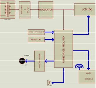
Circuit requires 12V DC forArduino board, motor driver 5V for microcontroller IC, LCD display 16x2 and sensor. This power supply can be provided by 12V step down transformer with rectifier-filter for converting AC ripples in to pure DC and regulator of 5V. You may have noticed the tilde (~) next to some of the digital pins (3, 5, 6, 9, 10, and 11 on the UNO). These pins act as normal digital pins, but can also be used for something called Pulse-Width Modulation (PWM).
Fig 1 Block Diagram
Is short for transmit, RX is short for receive. These markings appear quite a bit in electronics to indicate the pins responsible for serial communication. In our case, there are two places on the Arduino UNO where TX and RX appear once by digital pins 0 and 1, and a second time next to the TX and RX indicator LEDs (12). These LEDs will give us some nice visual indications whenever our Arduino is receiving or transmitting data (like when we’re loading a new program onto the board).
In this Arduino board (atmega328 28 pin microcontroller) works with 16MHz frequency used for (timer configuration), the unwanted frequency produced is bypassed by the capacitor of 27pf capacitor. Reset pin is connected to resistor of 10K whenever reset requires the reset switch (2 lead push to ON switch/ micro push to switch) required pressing. 6 channel 10 bit inbuilt ADC available, 6 PWM pins available, multiple serial communication available, up to 20 programmable pins available.
B. CIRCUIT DIAGRAM
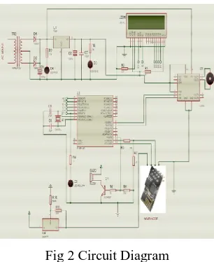
Fig 2 Circuit Diagram
MCU (atmega328 microcontroller) works with 16MHz frequency used for (timer configuration), the unwanted frequency produced is bypassed by the capacitor of 27pf capacitor. Reset pin is connected to resistor of 10K whenever reset requires the reset switch (2 lead push to ON switch/ micro push to switch) required pressing.
Atmega328 microcontroller pins 14, 15, 16, 17, 18, 19 are connected to LCD as RS, E, D4, D5, D6, D7 respectively. LCD shows text as our programming conditions.
Motor driver L293D 10, 15 pins are connected with microcontroller via 2, and 3 for control motor in clock and anti-clock direction.
Wi-Fi modem is connected to 12 and 13 pin of microcontroller to TX and Rx pin for Wi-Fi modem ESP8266. It requires 3.3V supply provided with LM317 variable voltage regulator, with 330 ohm and 560 ohm resistors.
All capacitors of 0.1uf & 100uf connected to reduce unwanted spikes in the circuit, spikes produced by inductive load/ sparking contacts of loads. Capacitor of 1000uf/25V at regulator output is connected for the cancel loading effect in the circuit while driving the high current source.
V.MODULES WITH WORKING PRINCIPLES
POWER SUPPLY:
Circuit requires 12V DC forArduino board, motor driver 5V for microcontroller IC, LCD display 16x2 and sensor. This power supply can be provided by 12V step down transformer with rectifier-filter for converting AC ripples in to pure DC and regulator of 5V.
POWER (USB / BARREL JACK):
Every Arduino board needs a way to be connected to a power source. The Arduino UNO can be powered from a USB cable coming from your computer or a wall power supply that is terminated in a barrel jack. In the picture above the USB connection is labeled (1) and the barrel jack is labeled (2).The USB connection is also load code onto your Arduino board
PINS (5V, 3.3V, GND, ANALOG, DIGITAL, PWM, AREF):
GND (3):
Short for ‘Ground’. There are several GND pins on the Arduino, any of which can be used to ground your circuit.
5V (4) & 3.3V (5):
As you might guess, the 5V pin supplies 5 volts of power, and the 3.3V pin supplies 3.3 volts of power. Most of the simple components used with the Arduino run happily off of 5 or 3.3 volts.
ANALOG (6):
The areas of pins under the ‘Analog In’ label (A0 through A5 on the UNO) are Analog In pins. These pins can read the signal from an analog sensor (like a light sensor) and convert it into a digital value that we can read.
DIGITAL (7):
Across from the analog pins are the digital pins (0 through 13 on the UNO). These pins can be used for both digital input (like telling if a button is pushed) and digital output (like powering an LED).
LCD DISPLAY
LCD stands for liquid crystal display. They come in many sizes 8x1 , 8x2 , 10x2 , 16x1 , 16x2 , 16x4 , 20x2 , 20x4 ,24x2 , 30x2 , 32x2 , 40x2 etc. Many multinational companies like Philips Hitachi Panasonic make their own special kind of LCD’s to be used in their products. All the LCD’s performs the same functions (display characters numbers special characters ASCII characters etc.)Their programming is also same and they all have same 14 pins (0-13) or 16 pins (0 to 15).
MOTOR DRIVER
Microcontroller has very low current output it cannot drive current consuming sources, such like relay hence relay driver circuit requires. We can implement this circuit using transistor or relay driver IC also.
VI.RESULT AND CONCLUSION
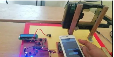
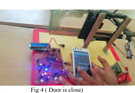
Result of our project is that when the door is open we can close the door if the door is close we can open door from anywhere, means we can control opening and closing of door from anywhere by using internet of things server.
Fig 3 Implemented Prototype(door is open)
Fig 4 ( Door is close)
The proposed IoT prototype is tested and implemented on a door successfully. This work can also have connected to the other application domains. This two fig.is the result of our project.
REFERENCES
1. Pradnya R. Nehete Dept. of ETC, Godavari College of Engineering, Jalgaon, India – 425001 J. P. Chaudhari, PhD CHARUSAT Space Research and Technology Center, Charotar University of Science and Tech., Changa,Gujarat, India S. R. Pachpande Dept. of ETC, J T Mahajan COE Faizpur, Maharashtra K. P. Rane, PhD Dept. of ETC, Godavari College of engineering Jalgaon, India - 425001
2. KeweiSha, RanadheerErrabelly, Wei Wei, T Andrew Yang, and Zhiwei Wang. Edgesec: Design of project IOT based secured gate access control system (ICFEC), 2017 IEEE 1st International Conference on, pages 81–88. IEEE,
3. Grant Ho, Derek Leung, PratyushMishra, AshkanHosseini, Dawn Song, and David Wagner. Smart locks: Lessons for securing commodity internet of things devices. Master’s thesis, University of California, Berkeley.
4. M. Yan and H. Shi, " Design of project IOT based secured gate access control”.
5. M. S. H. Khiyal, A. Khan, and E. Shehzadi, " Design of project IOT based secured gate access control Appliances and Security," Issues in Informing Science and Information Technology, vol. 6, pp. 887-894, 2009.