ISSN (Print) : 2320 – 3765 ISSN (Online): 2278 – 8875
I
nternational
J
ournal of
A
dvanced
R
esearch in
E
lectrical,
E
lectronics and
I
nstrumentation
E
ngineering
(An ISO 3297: 2007 Certified Organization)
Vol. 4, Issue 12, December 2015
Computer Aided Design Analysis of Electrical
Motor Drives for Traction Application.
B.Ravikumar1, Dr.Y.R.Manjunath2
Research Scholar, Dept. of EEE, Bangalore University, Bangalore, Karnataka, India
Professor, Dept. of EEE, Bangalore University, Bangalore, Karnataka, India
ABSTRACT: Strict environmental regulations and shrinkage of fossil fuel supplies necessitate the generation of electricity by using renewable energy sources. Most promising and popular source of green electricity is wind energy. WECS using DFIG is a meritorious option as it uses back to back power converters at a reduced rating, offers high controllability, allows maximum power extraction and individual control of active and reactive power components. As per modern grid rules, DFIG needs to operate without losing synchronism called low voltage ride through (LVRT) during severe grid faults. Hence, an enhanced field oriented control technique (EFOC) was adopted in Rotor Side Converter (RSC) of DFIG with PI and PI-Resonant Controller separately to improve the power flow transfer and to improve dynamic and transient stability and the corresponding results are studied. This paper mitigates voltage and limits surge currents to enhance the operation of DFIG during symmetrical and asymmetrical faults. The system performance with different types of grid faults like single line to ground, double line to ground and triple line to ground were applied with PI and PIR controller separately and the corresponding waveforms are presented by using MATLAB/Simulink software.
KEYWORDS: DFIG Doubly Fed Induction Generator, EFOC Enhanced Field Oriented Control, LVRT Low Voltage Ride Through, WECS Wind Energy System.
I. INTRODUCTION
ISSN (Print) : 2320 – 3765 ISSN (Online): 2278 – 8875
I
nternational
J
ournal of
A
dvanced
R
esearch in
E
lectrical,
E
lectronics and
I
nstrumentation
E
ngineering
(An ISO 3297: 2007 Certified Organization)
Vol. 4, Issue 12, December 2015
control strategies for the rotor side converter (RSC). A fast response vector-based hysteresis current controller was used to achieve DFIG LVRT Requirement [14], [15]. By limiting output of stator active power to reduce rotor currents during grid faults was proposed in [16] and [17]. This method works well under steady state and [16] Improves [17] by injecting reactive power into the grid. These methods achieve LVRT requirement by only improving the dynamic response of the control system or limiting the output powers, but do not damp the stator flux. Therefore, the DFIG may become uncontrollable, and the rotor may suffer from Over-current under some conditions. The stator flux may include positive and negative sequence components, as well as transient component during grid faults [18]. The stator flux-based control strategies were proposed to fulfill LVRT requirement in [19]–[21]. In [20], a virtual
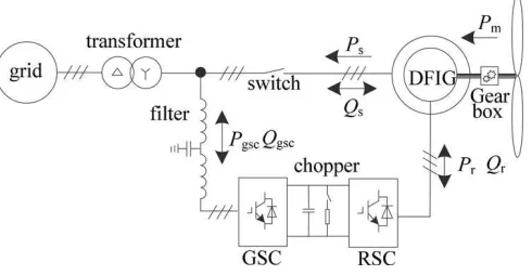
Fig. 1. Structure diagram of a DFIG-based WECS.
resistance was used to improve the control strategy presented in [19] by increasing the damping ratio so that the transient flux can decay fast. However, during asymmetrical grid faults, the control of the negative sequence stator flux is not as important as the transient stator flux, because it cannot disappear like the transient flux. The control of negative sequence flux may slow the decaying speed of the transient flux, and increase the rotor current amplitude. Moreover, the electromagnetic torque is fluctuant during grid faults. On the other hand, it is difficult to improve the performances of DFIG during unbalanced grid faults [19], [20]. In [21], a flux linkage tracking control strategy was proposed for DFIG to achieve LVRT requirement. However, the reactive power required by grid code is not involved. Reduction of torsional oscillation as the control target was introduced to improve DFIG performances during asymmetrical grid fault, but the influence of magnetic nonlinearity characteristic is not considered in [22]. When the grid voltage is unbalanced, considering the magnetic nonlinearity characteristics, the grid connected DFIG may be regarded as an equivalent circuit with unbalanced power source and unbalanced load. Then, the performance of DFIG is degraded.
ISSN (Print) : 2320 – 3765 ISSN (Online): 2278 – 8875
I
nternational
J
ournal of
A
dvanced
R
esearch in
E
lectrical,
E
lectronics and
I
nstrumentation
E
ngineering
(An ISO 3297: 2007 Certified Organization)
Vol. 4, Issue 12, December 2015
II. DFIG PERFORMANCES
The structure diagram of the DFIG-based WECS is shown in Fig. 1. In the stationary reference frame, the DFIG voltage and flux equations, in the form of vector, are expressed as
s s
u
s Rs is p s
s
s s s
(1)
u
r Rr ir p r j r r
s s s
s Lm ir Ls is
s s s
r Lr ir Lm is
where u, i, and ϕ are the vectors of voltage, current, and flux, respectively, R is the resistance, and L is the inductance. Subscripts “s” and “r” distinguish the stator and rotor variables. Superscript “s” represents the stationary reference frame. Lm is the mutual inductance, p stands for the differential operator, and ωr is the rotor electrical frequency.
Replacing the stator current with stator flux and rotor current, the stator voltage equation in (1) is re-expressed as
s s
R
s
R L
s (2)
s s
m
p s us
L s s L s i r
The rotor current may be expressed as
irs Irmej( st ) (3)
where a tan(i i ), I
r
m
i2 i2 , “d” and “q”
rq
r
d rq
r
d
represent d and q-axes components, respectively, in the synchronous reference frame.
In Fig. 1, due to a wye-delta isolation transformer, during asymmetrical grid faults, the stator voltage may only include
positive and negative sequence components and be expressed as
s s s
us us us
ISSN (Print) : 2320 – 3765 ISSN (Online): 2278 – 8875
I
nternational
J
ournal of
A
dvanced
R
esearch in
E
lectrical,
E
lectronics and
I
nstrumentation
E
ngineering
(An ISO 3297: 2007 Certified Organization)
Vol. 4, Issue 12, December 2015
Usm
where superscripts “+” and “−” represent positive and negative sequence components, respectively. Usm represents voltage
amplitude.
By substituting (3) (4) into (2), it results in
s
s
t s s
L
m (5)
u
s us Rs ir
s Ce 1 1 Ls 1 j j j s s s
where LsRs is the stator time constant and C is the initial
amplitude of the transient stator flux.
On the right side of (5), the first term is the transient component of stator flux, and the other three terms are steady-state
components of stator flux. During grid voltage drop and recovery, the stator transient component may exist, while in the
steady state, it is equal to zero.
Given that a grid fault occurs at t0 , the stator voltage is expressed as
where subscripts “1” and “2” distinguish the values before and after grid fault. If the grid voltage is balanced, the negative
sequence component of the stator voltage is equal to zero.
ISSN (Print) : 2320 – 3765 ISSN (Online): 2278 – 8875
I
nternational
J
ournal of
A
dvanced
R
esearch in
E
lectrical,
E
lectronics and
I
nstrumentation
E
ngineering
(An ISO 3297: 2007 Certified Organization)
Vol. 4, Issue 12, December 2015
As the stator flux is a state variable and continuous at t0, if rotor current is under control, from (7), it is obtained that
In (8), it can be seen that C2 is not only determined by the instants and depths of voltage variations, but also the
amplitude of the transient flux C1e t , which is the first term on the right of (8). Therefore, if the transient flux is equal
to zero at t0, it may avoid the amplitude of the new transient flux C2e (t t0) being
too large.
By replacing the rotor flux with stator flux and rotor current, the rotor voltage equation in (1) may be re-expressed as
If the rotor current is equal to zero, (9) may be re-expressed as
When rotor current is equal to zero, from (2), it may be derive that
ISSN (Print) : 2320 – 3765 ISSN (Online): 2278 – 8875
I
nternational
J
ournal of
A
dvanced
R
esearch in
E
lectrical,
E
lectronics and
I
nstrumentation
E
ngineering
(An ISO 3297: 2007 Certified Organization)
Vol. 4, Issue 12, December 2015
In (12), if the module of s is larger than the maximum
u
r 0
amplitude supplied by the RSC, the rotor current may become uncontrollable, which may potentially destroy the RSC. Therefore, the stator flux may cause the DFIG to be out of control. A possible way to reduce the module of s is to reduce
u
r 0
the amplitude of the transient component, because the positive and negative sequence voltages are directly determined by the
grid. From (8), when grid voltage varies at t0, if is not
equal to zero, it may lead to a large transient flux C2e (t t0) .
Therefore, if a strategy can suppress the transient flux fast, the rotor over-current may be avoided.
The electromagnetic torque is expressed as
where superscript “^” represents conjugation of vector. The stator active and reactive powers are expressed as
III.PROPOSED CONTROL STRATEGIES
A. ENHANCED FIELD ORIENTED CONTROL
The field orientation techniques allow decoupled or independent control of both active and reactive power. These techniques are based on the concept of de- qe controlling in different reference frames, where the current and the voltage are decomposed into distinct components related to the active and reactive power. In this work, the stator flux oriented rotor current control, with decoupled control of active and reactive powers is adopted.
The control schemes for the doubly-fed induction machine are expected to track a prescribed maximum power curve, for maximum power capturing and to be able to control the reactive power generation. These control objectives must be achieved with adequate stability of the system which also includes the power converter and the dc link.
Ps
3
| Vs | iqse (15)
2
3 e
(16)
Qs
| Vs | ids
2
ISSN (Print) : 2320 – 3765 ISSN (Online): 2278 – 8875
I
nternational
J
ournal of
A
dvanced
R
esearch in
E
lectrical,
E
lectronics and
I
nstrumentation
E
ngineering
(An ISO 3297: 2007 Certified Organization)
Vol. 4, Issue 12, December 2015
Where | Vs | (Vdse )2 (Vqse )2
The field orientation control is based on the field de- qe model, where the reference frame rotates synchronously with respect to the stator flux linkage, with the d-axis of the reference frame instantaneously overlaps the axis of the stator flux. By aligning the stator flux phasor λs on the de - axis, so (ω= ωeand λ qse= 0, s e ds λdse=λs ). In such case the following
expressions are obtained
The developed electromagnetic torque can be expressed in terms of de- qe stator current and flux components as:
By putting λeqs =0 , in the torque equation, this yields:
(19)
Using (17) in and the active power equation (15), the equation of active power becomes
(20)
21.
Using (21) and the reactive power equation (15), the equation of the reactive power can be expressed as follows:
ISSN (Print) : 2320 – 3765 ISSN (Online): 2278 – 8875
I
nternational
J
ournal of
A
dvanced
R
esearch in
E
lectrical,
E
lectronics and
I
nstrumentation
E
ngineering
(An ISO 3297: 2007 Certified Organization)
Vol. 4, Issue 12, December 2015
Therefore, the d e -axis rotor current component, ( iedr ) can be obtained by regulating the stator reactive power. On the
other
hand, the qe –axis rotor current component, ( ieqr ) can be obtained by controlling the generated torque which is obtained
from the stator active power and the generator speed.
The stator flux linkage components in the stationary stator reference frame can be calculated through the integration of
the difference between the phase voltage and the voltage drop in the stator resistance as;
(23)
The magnitude of the stator flux linkage and its phase angle are given by:
(24)
In Enhanced Field Oriented Control (EFOC) the direct and quadrature axis (d and q axis) currents are used to control effectively flux decay during symmetrical or asymmetrical faults. The rotor speed is multiplied with pole numbers and is subtracted from angular grid synchronous frequency. Later it is integrated and given a90o phase shift to get rotor slip
injection frequency angles (θs). At this slip frequency RSC converter injects current into the rotor circuit to control the
ISSN (Print) : 2320 – 3765 ISSN (Online): 2278 – 8875
I
nternational
J
ournal of
A
dvanced
R
esearch in
E
lectrical,
E
lectronics and
I
nstrumentation
E
ngineering
(An ISO 3297: 2007 Certified Organization)
Vol. 4, Issue 12, December 2015
Fig. 2. MATLAB EFOC Subsystem in the RSC Controller.
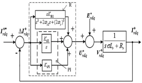
B. PIR CONTROLLER
The positive- and negative-sequence currents must be controlled precisely in order to meet the control objectives. Good current control depends on the accuracy of the d–q components’ decoupling and the removal of network voltage disturbance. Typical RSC (DFIG) and GSC control designs employ two current controllers implemented in the positive and negative synchronous reference frames, respectively [23], [24], [25]. However, the positive- and negative-sequence components of the currents have to be decomposed from measured signals involving time delay and resulting in amplitude and phase errors. Consequently, the systems cannot be fully decoupled during transients, degrading system performance and stability. In order to overcome these problems, the strategy adopted here is to have a PI–R current controller [26], [28], [27]. The R regulator has been widely presented as an interesting alternative in the stationary frame to the use of synchronous PI controllers [29]–[31], [28]. This regulator generally consists of a proportional and an integrator term, which contains an R pole, with the aim of obtaining an infinite gain at the R frequency. In order to reduce the sensitivity toward possible grid frequency variation, a component with a cutoff frequency of ωc1 can be inserted into the R part to widen its frequency bandwidth, as shown in Fig. 3.
Fig.3. Rotor current control scheme based on PI–R controller in the dq+ reference frame.
ISSN (Print) : 2320 – 3765 ISSN (Online): 2278 – 8875
I
nternational
J
ournal of
A
dvanced
R
esearch in
E
lectrical,
E
lectronics and
I
nstrumentation
E
ngineering
(An ISO 3297: 2007 Certified Organization)
Vol. 4, Issue 12, December 2015
reference frame can directly regulate both positive- and negative-sequence components without involving sequential decomposition.
C. ASYMMETRICAL GRID FAULTS
When the grid voltage is unbalanced, the active and reactive powers may be expressed as
(25) with
where α and β represent the α and β-axes components
in the stationary reference frame, respectively. The
electromagnetic torque may be expressed as
Te = Te_A + Te_B + ET (27)
with
ISSN (Print) : 2320 – 3765 ISSN (Online): 2278 – 8875
I
nternational
J
ournal of
A
dvanced
R
esearch in
E
lectrical,
E
lectronics and
I
nstrumentation
E
ngineering
(An ISO 3297: 2007 Certified Organization)
Vol. 4, Issue 12, December 2015
IV. SIMULATION RESULTS & DISCUSSION
Fig.4. MATLAB based DFIG Model.
A. WITH PI CONTROLLER
ISSN (Print) : 2320 – 3765 ISSN (Online): 2278 – 8875
I
nternational
J
ournal of
A
dvanced
R
esearch in
E
lectrical,
E
lectronics and
I
nstrumentation
E
ngineering
(An ISO 3297: 2007 Certified Organization)
Vol. 4, Issue 12, December 2015
Fig.5. Simulation result of DFIG Performance with Terminal Voltage and current during a LG fault using a PI Controller. Fig.6. Simulation result of DFIG Performance with Terminal Voltage and current during a LLG fault using a PI Controller
Fig.7. Simulation result of DFIG Performance with Terminal Voltage and current during a LLLG fault using a PI Controller.
Fig.8. Simulation result of DFIG Performance with Terminal Voltage and current during a LG fault using a PIR
Controller.
B. WITH PI-RESONANT CONTROLLER
ISSN (Print) : 2320 – 3765 ISSN (Online): 2278 – 8875
I
nternational
J
ournal of
A
dvanced
R
esearch in
E
lectrical,
E
lectronics and
I
nstrumentation
E
ngineering
(An ISO 3297: 2007 Certified Organization)
Vol. 4, Issue 12, December 2015
waveforms are shown in the Fig.8 to Fig.10 respectively. The figures indicate the terminal voltage and current of the DFIG during the pre-fault, during fault and post-fault.
Fig.9. Simulation result of DFIG Performance with Terminal Voltage and current during a LLG fault using a PIR Controller.
Fig.10. Simulation result of DFIG Performance with Terminal Voltage and current during a LLLG fault using a PIR
Controller.
V. CONCLUSION
A conventional DFIG system connected considered with three different faults like SLG, DLG and TLG are analyzed with PI Controller and PIR Controller separately. The three faults are imagined to occur at PCC between 0.6 and 0.8s with
a fault resistance of 0.01 Ω. The drop in rotor and GSC terminal voltage during fault remained asymmetric faults and reached half for symmetric fault. With the proposed EFOC technique, rotor current during any fault did not reach zero in magnitude. Therefore, the whole system is to be disconnected from the grid during severe voltage dips but this is not acceptable by the new grid requirements, which require wind turbines to have LVRT capability and this was achieved in our paper.
APPENDIX
The parameters of DFIG used in
simulation are:
Rated Power = 1.5MW,
Rated Voltage = 690 V,
Stator Resistance Rs = 0.0049pu,
Rotor Resistance Rr1 = 0.0055pu,
Stator Leakage Inductance Lls = 0.093
pu,
Rotor Leakage inductanceLlr1 = 0.1pu,
Inertia constant = 4.9 pu,
Number of poles = 4,
ISSN (Print) : 2320 – 3765 ISSN (Online): 2278 – 8875
I
nternational
J
ournal of
A
dvanced
R
esearch in
E
lectrical,
E
lectronics and
I
nstrumentation
E
ngineering
(An ISO 3297: 2007 Certified Organization)
Vol. 4, Issue 12, December 2015
DC link Voltage = 415V,
Dc link capacitance = 0.2 F,
Wind speed = 14m/s.
Grid Voltage = 25 kV,
Grid frequency = 60 Hz.
Grid side Filter Rfg = 0.3 Ω,
Lfg = 0.6 nH
Transformer-690/440V, 50 kVA rating.
REFERENCES
[1] “Technical regulation 3.2.5 for wind power plants with a power output greater than 11 kW,” (Energinet.dk, Sept. 2010). [Online]. Available: http://www.energinet.dk/EN/El/Forskrifter/Technical-regulation s/Sider/Regulations-for-grid-connection.aspx
[2] “Grid Code High and Extra high voltage” (B. E. ON Netz GmbH, 2006, Apr.). [Online]. Available:
http://www.pvupscale.org/MG/pdf/D4_2_DE_annex_A-3_EON_HV_grid__connection_ requirements_ENENARHS2006de.pdf
[3] S. Muller, M. Deicke, and R. W. De Doncker, “Doubly fed induction generator systems for wind turbines,” IEEE Ind. Appl. Mag., vol. 8, no. 3, pp. 26–33, May/Jun. 2002.
[4] Petersson, T. Thiringer, L. Harnefors, and T. Petru, “Modeling and experimental verification of grid interaction of a DFIG wind turbine,” IEEE Trans. Energy Convers., vol. 20, no. 4, pp. 878–886, Dec. 2005.
[5] J. Lopez, E. Gubia, E. Olea, J. Ruiz, and L. Marroyo, “Ride through of wind turbines with doubly fed induction generator under symmetrical voltage dips,” IEEE Trans. Ind. Electron., vol. 56, no. 10, pp. 4246–4254, Oct. 2009.
[6] G. Pannell, D. J. Atkinson, and B. Zahawi, “Minimum-threshold crowbar for a fault-ride-through grid-code-compliant DFIG wind turbine,” IEEE Trans. Energy Convers., vol. 25, no. 3, pp. 750–759, Sep. 2010.
[7] A. O. Ibrahim, N. Thanh-Hai, L. Dong-Choon, and K. Su-Chang, “A fault ride-through technique of DFIG wind turbine systems using dynamic voltage restorers,” IEEE Trans. Energy Convers., vol. 26, no. 3, pp. 871– 882, Sep. 2011.
[8] C. Wessels, F. Gebhardt, and F. W. Fuchs, “Fault ride-through of a DFIG wind turbine using a dynamic voltage restorer during symmetrical and asymmetrical grid faults,” IEEE Trans. Power Electron., vol. 26, no. 3, pp. 807–815, Mar. 2011.
[9] Y. Xiangwu, G. Venkataramanan, P. S. Flannery, W. Yang, D. Qing, and Z. Bo, “Voltage-sag tolerance of DFIG wind turbine with a series grid side passive-impedance network,” IEEE Trans. Energy Convers., vol. 25, no. 4, pp. 1048–1056, Dec. 2010.
[10] Y. Xiangwu, G. Venkataramanan, W. Yang, D. Qing, and Z. Bo, “Gridfault tolerant operation of a DFIG wind turbine generator using a passive resistance network,” IEEE Trans. Energy Convers., vol. 26, no. 10, pp. 2896–2905, Oct. 2011.
[11] P. S. Flannery and G. Venkataramanan, “A fault tolerant doubly fed induction generator wind turbine using a parallel grid side rectifier and series grid side converter,” IEEE Trans. Power Electron., vol. 23, no. 3, pp. 1126–1135, May 2008.
[12] P. S. Flannery and G. Venkataramanan, “Unbalanced voltage sag ridethrough of a doubly fed induction generator wind turbine with series gridside converter,” IEEE Trans. Ind. Appl., vol. 45, no. 5, pp. 1879–1887, Sep./Oct. 2009.
[13] G. Pannell, B. Zahawi, D. J. Atkinson, and P. Missailidis, “Evaluation of the performance of a DC-Link brake chopper as a DFIG low-voltage fault-ride-through device,” IEEE Trans. Energy Convers., vol. 28, no. 3, pp. 535–542, Sep. 2013.
[14] M. Mohseni, S. Islam, and M. A. S. Masoum, “Fault ride-through capability enhancement of doubly-fed induction wind generators,” IET Renew. Power Gener., vol. 5, no. 5, pp. 368–376, Sep. 2011
[15] M. Mohseni and S. M. Islam, “Transient control of DFIG-based wind power plants in compliance with the Australian grid code,” IEEE Trans. Power Electron., vol. 27, no. 6, pp. 2813–2824, Jun. 2012.
[16] X. Dongliang, X. Zhao, Y. Lihui, J. Ostergaard, X. Yusheng, and W. Kit Po, “Acomprehensive LVRT control strategy for DFIGwind turbines with enhanced reactive power support,” IEEE Trans. Power Syst., vol. 28, no.3, pp. 3302–3310, Aug. 2013.
[17] Y. Lihui, X. Zhao, J. Ostergaard, D. Zhao Yang, and W. Kit Po, “Advanced control strategy of DFIG wind turbines for power system fault ride through,” IEEE Trans. Power Syst., vol. 27, no. 2, pp. 713–722, May 2012.
[18] J. Lopez, E. Gubia, P. Sanchis, X. Roboam, and L. Marroyo,
“Wind turbines based on doubly fed induction generator under asymmetrical voltage dips,” IEEE Trans. Energy Convers., vol. 23, no. 1, pp. 321–330, Mar. 2008.
[19] X. Dawei, L. Ran, P. J. Tavner, and S. Yang, “Control of a doubly fed induction generator in a wind turbine during grid fault ride-through,” IEEE Trans. Energy Convers., vol. 21, no. 3, pp. 652–662, Sep. 2006.
[20] H. Sheng, L. Xinchun, K. Yong, and Z. Xudong, “An improved lowvoltage ride-through control strategy of doubly fed induction generator during grid faults,” IEEE Trans. Power Electron., vol. 26, no. 12, pp. 3653–3665, Dec. 2011.
[21] X. Shuai, Y. Geng, Z. Honglin, and G. Hua, “An LVRT control strategy based on flux linkage tracking for DFIG-based WECS,” IEEE Trans. Ind Electron., vol. 60, no. 7, pp. 2820–2832, Jul. 2013.
ISSN (Print) : 2320 – 3765 ISSN (Online): 2278 – 8875
I
nternational
J
ournal of
A
dvanced
R
esearch in
E
lectrical,
E
lectronics and
I
nstrumentation
E
ngineering
(An ISO 3297: 2007 Certified Organization)
Vol. 4, Issue 12, December 2015
[23] H. S. Song and K. Nam, “Dual current control scheme for PWM converter under unbalanced input voltage conditions,” IEEE Trans. Ind. Electron., vol. 46, no. 5, pp. 953–959, Oct. 1999.
[24] L. Xu and Y.Wang, “Dynamic modeling and control of DFIG based wind turbines under unbalanced network conditions,” IEEE Trans. Power Syst., vol. 22, no. 1, pp. 314–323, Feb. 2007.
[25] J. B. Hu, Y. K. He, and H. Nian, “Enhanced control DFIG-used back-toback PWM VSC under unbalanced grid voltage conditions,” J. Zhejiang Univ. Sci. A, vol. 8, no. 8, pp. 1330–1339, Aug. 2007.
[26] M. Liserre, R. Teodorescu, and F. Blaabjerg, “Multiple harmonics control for three-phase grid converter systems with the use of PI–RES current controller in a rotating frame,” IEEE Trans. Power Electron., vol. 21, no. 3, pp. 1–6, May 2006.
[27] R. Teodorescu et al., “Proportional–resonant controllers and filters for grid-connected voltage-source converters,” Proc. Inst. Elect. Eng.— Elect. Power Appl., vol. 153, no. 5, pp. 750–762, Sep. 2006.
[28] I. Etxeberria-Otadui, A. Lopez De Heredia, H. Gaztanaga, S. Bacha, and M. R. Reyero, “A single synchronous frame hybrid (SSFH) multi frequency controller for power active filters,” IEEE Trans. Ind. Electron., vol. 53, no. 5, pp. 1640–1648, Oct. 2006.
[29] J. B. Hu and Y. K. He, “Multi-Frequency Proportional–Resonant (MFPR) current controller for PWM VSC under unbalanced supply conditions,” J. Zhejiang Univ. Sci. A, vol. 8, no. 10, pp. 1527–1531, Oct. 2007.
[30] G. Escobar, A. M. Stankovic, and P. Mattavelli, “An adaptive controller in stationary reference frame for D-statcom in unbalanced operation,” IEEE Trans. Ind. Electron., vol. 51, no. 2, pp. 401–409, Apr. 2004.