International Journal of Research (IJR)
e-ISSN: 2348-6848, p- ISSN: 2348-795X Volume 2, Issue 06, June 2015Available at http://internationaljournalofresearch.org
Mechanical study of hole specimens extracted from the outer
sheath of an underground electrical cable LV H1XDVAS
and subjected to tensile test
H.Ouaomar1; N.Mouhib1; M. Lahlou1; A .Tijani1 & M. El Ghorba1
1Laboratory of Control and Mechanical Characterization of Materials and Structures, National
Higher School of Electricity and Mechanics, BP 8118 Oasis, Hassan II University, Casablanca, Morocco
EMAIL: [email protected]
Abstract
Due to their multiple uses, polymer materials play an essential role in the insulation of electrical systems. Thus, maintaining the insulation function is crucial because it is one of the fundamental conditions of equipment performance atgeneration, transmission and distribution of electrical energy.
There are various causes on the origin of the insulation degradation. As a result ofoperating conditions of electrical cables, the insulation material is subjected to mechanical, electrical and thermal constraints. Moreover the direct contact of outer sheathwith external environment makes them vulnerable to mechanicalconstraints.
Cables reliability could largely be determined by the sustainability of the different mechanical properties of the insulation. For this, we treated in this work the mechanical behavior of electrical outer sheath and specifically the behavior of ahole specimen to simulate the artificial damage in an outer sheath of an underground electric cable. Thereafter, a static damage-reliability study is established.
Key Words:
Outer sheath; reliability; damage; tensile test; hole specimen
1.
Introduction
In the electric domain, the application fields ofsolid organic insulators (polymers) are extended: power transmission lines, telecommunication cables... The use of these materials in the electrical insulation has several advantages such as: excellent electrical properties (resistivity, stiffness and permittivity), good mechanical and tri-biological performance without forgetting its dimensional stability. Add to this list, the easy implementation, low weight and sometimes the possibility of recycling [1].
On the other hand, in low-voltage,insulation materials (PVC and XLPE) are selected by dint of their improved thermo mechanical properties, they are thermostable (160 ° C continuously) andmechanically resistant to various applied forces.
International Journal of Research (IJR)
e-ISSN: 2348-6848, p- ISSN: 2348-795X Volume 2, Issue 06, June 2015Available at http://internationaljournalofresearch.org
2.
Experimentation
2.1Mechanical characterizationOur approach is to study the mechanical behavior of the outer sheath PVC belonging to an underground electric cable LV (Low Voltage) H1XDVAS.
Figure 1: Underground electric cable H1XDV AS
The outer sheath is cut with a suitable shaving apparatus (sharp knife, razor blade, etc.) after removing it from the other various elements of the cable,. Each sample is prepared in appropriate length stretches. After this, standardized specimens are cut for mechanical characterization in the virgin state of the material [3]. Different mechanical characteristics are extracted from the curve and represented in Table1[4]:
Table 1: Mechanical properties of flexible PVC
2.2Studied specimen
We used the specimen in conformity with the ASTM standard [5] to study the effect of the hole on the mechanical behavior of the studied material. The dimensions of rectangular test specimen are represented in Figure 2.
Figure 2: Rectangular Test specimen according to ASTM [5] standard.
Different hole specimens diameters are applied from 1 to 7mm on rectangular samples, and then a tensile test of three specimens for each hole specimens diameter is realized.
3.
Results and discussion
3.1Static tensile test on hole specimens:The test curve of the applied stress as a function of the strain at different holediameters is given by Figure 3.
Figure 3 stress-strain curves at different hole specimens diameters
According to this figure, the variouscurves associated to hole diameters are superimposed in order, a decrease in the ultimate stress depending on the diameter of the hole is noticed, the degradation of the mechanical properties is clearly seen: elastic stress, elongation... rupture tends toward brutality and preceded by a local plastification.
Elastic stress 𝝈𝒆(MPa)
Breaking stress 𝝈𝒓(MPa)
Strain 𝜺 (%)
Young modulu s E(MPa)
Specific energy Wm
Maximum stress 𝝈𝒖(MPa)
International Journal of Research (IJR)
e-ISSN: 2348-6848, p- ISSN: 2348-795X Volume 2, Issue 06, June 2015Available at http://internationaljournalofresearch.org
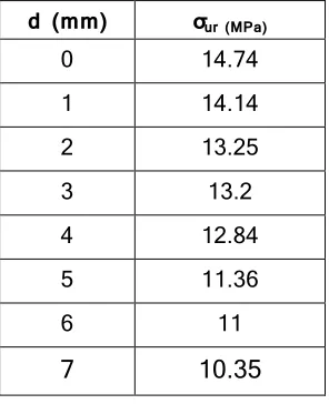
Table 2 Values of ultimate residual stresses
d (mm) σur (MPa)
0 14.74
1 14.14
2 13.25
3 13.2
4 12.84
5 11.36
6 11
7 10.35
3.2Calculation of static damage
The model of static damage is to determine the evolution of the stress as a function of the fraction of life
β = d/w. Damage is determined by the
variable D:
D =
1−ur u
1−au(1)
Where:
σu: the value of the ultimate stress in the initial state
σur: the value of the ultimate residual stress σa: stress just before failure
a: length of notch w: notch width
During the test, the variation of the damage depending on the life fraction is illustrated by the curve in Figure 4.
Figure 4 Evolution of damage depending on the life fraction
Increased damage means the increase in the resistance loss of static tensile strength of the samples, the loss changes when the life fraction becomes more important. After a
value of β = 0.8, the damage reaches the maximum value: it is a complete break
When a system is in function under stress, its physical properties undergo progressive degradation. So we often need to reduce the probability of sudden failure.
The reliability theory assesses a probability of failure and considers the uncertainties associated with different variables.
Characterized by the performance limits of a structure to ensure good condition of functioning, complementarities of these two probabilistic notions result the following relation:
R (β) + D (β) = 1 (2)
The resulting equation allows us to plot the variation of reliability with the damage:
Figure 5: Superposition of curves Damage - Reliability depending on the life fraction From Figure 5, in the presence of default, three stages are distinguished:
International Journal of Research (IJR)
e-ISSN: 2348-6848, p- ISSN: 2348-795X Volume 2, Issue 06, June 2015Available at http://internationaljournalofresearch.org
Stage I: The curve represents a linear behavior at the beginning, then a sudden change (growth-decline) is noted for the two curves (damage and reliability);
Stage II: there is a stabilization area in which is situated the intersection reliability-damage;
Stage III: represents the unstable zone in which the default could not be controlled.
3.3 Damage calculation by unified theory
The level of loading applied to a material plays a crucial role in behavior of its damage .The unified theory carefully handles the loading level factor that changes each time
depending on γ =σ
σ0 .
In analogy with the unified theory, an empirical relationship describing the damage is proposed:
D = β
β+ 1−β [γ −(γ γ u )
8
γ −1 ] Where: β =d
w , γ = σ
σ0 andγu =
σu
σ0
σ0 is the residual endurance limit which is
equal to the residual ultimate stress
multiplied by a coefficient α
(For n = 0, σ0= α σu).
We used security coefficient of the material
(CS=3); and we have α = 1
cs
The variation of damage depending on β is
shown in Figure 8. Each curve is associated to a loading level.
We can also represent Miner curve as the simplest damage curve, each life fraction is
associated to a damage value (β= 0, D = 0, β
= 1, D = 1).
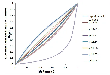
Comparing the damage curve by the unified theory and the experimental obtained by calculating static damage, we noticed that
the experimental damage is more dangerous
than theoretical one calculated by unified theory.
Figure 6: Experimental damage and unified theory damage curves in function of life fraction
The result according to the unified theory (equation 3) is shown in Figure 6. It is observed that gait curves relating to various
loading levels are superposed according to γ
order (the upper curve is the one with the highest load level) .The curve illustrating the
last load γ = 14.14 MPa shows a significant difference compared to the others.
The linear Miner rule is the most critical compared to different damage curves of the unified theory. However, the experimental damage curve is considered the most critical of all the curves of the presented damage.
4. Conclusion
A damage and reliability study was conducted based on a static tensile test, which was used to estimate the life time of an outer sheath belonging to an underground electric cable H1XDV AS.
The establishment of the relationship Damage-Reliability identifies three stages of damage and permits to predict the moment of critical damage, so moving towards predictive maintenance.
A comparison between the experimental damage and those of the unified theory with different load levels is carried out, and it is noticed that the unified theory in different loading levels is less critical than the experimental damage, but the Miner law curve is the closest one to the reality.
International Journal of Research (IJR)
e-ISSN: 2348-6848, p- ISSN: 2348-795X Volume 2, Issue 06, June 2015Available at http://internationaljournalofresearch.org
Références
[1] N.LAHOUD « Modélisation du vieillissement des isolants organiques sous contraintes électriques : application a la fiabilité des matériaux »Université DE GRENOBLE, 2006 .
[2] P.QUENNEHEN« Étude de la dégradation de la fonction isolation de câbles HT isolés au PVC» Université de Toulouse,2009 .
[3] ISO 6801-1 (International Organization for Standardization standard electrical cables).
[4] H.OUAOMAR &Al”Study of the damage SENT specimen of the outer sheath of an underground electrical cable BT H1XDVAS submitted for a
static test” International Journal of Mechanical Engineering (IIJME), vol. 3, issue 4., pp. 049–053, April 2015.