Available online:
https://edupediapublications.org/journals/index.php/IJR/
P a g e | 9135G Communications Multiband Antenna Design
Kiruthika V
1, Dr. V.Thulasi Bai
21
student, Department of ECE, KCG College of Technology.
2
Head of the Department, Department of ECE, KCG College of Technology
Abstract—.In this paper, a novel reconfigurable antenna with multiband of frequency is analysed and simulated for the modern 5G mobile communication applications. The proposed antenna is simulated by applying ADS software and fed through strip line feed ing. The uniqueness of this design is the antenna can support 2.4-GHz Bluetooth and/or 3.5-GHz WiMAX and/or 5.8-GHz WLAN systems and/or 6GHz 5G systems. The advantage of this design is that it overcomes the problem of conventional reconfigurable antennas of serving one frequency band at a time. Maximum radiations are directed normal to patch geometry and shape of patterns is somewhat similar to a dumble shape in the upper hemisphere. The antenna design, simulation, and measurement results are presented. The antenna shows similar radiation patterns with low cross-polarization levels at all its operating frequencies. The simulated and measured results are in good agreement. This Reconfigurable Patch antenna is specifically designed for the application of 5G Mobile communication systems.
I. INTRODUCTION
There is a developmental trend in wireless communication system that demands the use of antennas capable of accessing services in various frequency bands [1], sometimes with the use of a single antenna [2]. The increasing demand for modern mobile, satellite and wireless communication systems in the world make many researchers worked hard in order to improve the performances and enhance the application of the Microstrip Patch Antenna (MSA). Reconfigurable antenna will be an attractive feature in the modern wireless communication system because it enables to provide a single antenna to be used for multiple systems [3]. Due to their capability to vary their operating frequency, radiation pattern and polarization, it also has great attention in wireless communication systems. In this case, we need a reconfigurable antenna that maintains its radiation pattern at different frequencies.
II. ANTENNA DESIGN AND ANALYSIS
Here, the design and implementation of Multiband Rectangular Microstrip antenna is presented. The antenna is designed the uniqueness of this design is the antenna can support 2.4-GHz Bluetooth and/or 3.5-GHz WiMAX and/or 5.8-GHz WLAN systems and/or 6GHz 5G systems. For designing this antenna microstrip feeding technique is used. The return loss and smith chart have also been studied.
The three essential parameters involved in design procedure of the antenna are:
Frequency of operation ( ): The resonant frequency of the antenna must be selected appropriately. . The resonant frequencies selected for the design here is 2.4-GHz Bluetooth and/or 3.5-GHz WiMAX and/or 5.8-GHz WLAN systems and/or 6GHz 5G systems.
Available online:
https://edupediapublications.org/journals/index.php/IJR/
P a g e | 914the antenna but it also affects the antenna performance. So, there is a trade-off between size and performance of patch antenna.
Height of dielectric substrate (h): For the Microstrip patch antenna to be used wireless communication systems, it is essential that the antenna is not bulky. Hence, the height of the dielectric substrate should be less.
After the proper selection of above three parameters, the next step is to calculate the radiating
Patch width and length of the antenna for the operating frequencies. Also finally optimize the obtained values for deriving the required characteristics from the proposed antenna.
Effective dielectric constant
(1) Where = Effective dielectric constant.
= Dielectric constant of substrate.
h = Height of dielectric substrate.
W = Width of the patch.
The dimensions of the patch along its length have now been extended on each end by a distance ,
which is given empirically as:
(2)
The effective length of the patch now becomes:
(3)
The final patch length L is given as:
(4) For a rectangular Microstrip patch antenna, the resonance frequency for anyTM10 mode is given as:
(5)
Where m and n are modes along L and W respectively.
For efficient radiation, the width W is given as:
(6)
Available online:
https://edupediapublications.org/journals/index.php/IJR/
P a g e | 915The transmission line model even though is applicable to infinite ground planes only but for practical considerations, a finite ground plane is used. However, size of ground plane should be greater than the patch dimensions by approximately six times the substrate thickness all around the periphery so that results are similar to the one using infinite ground plane. The ground plane dimensions are calculated as:
(7) (8)
The design procedure is as follows:
(a) Substrate Selection:
The substrate selected for the design of the antenna is FR4 with thickness (h) of 1.6 mm and relative permittivity = 4.6 and a loss tangent of 0.09.
(b) Calculation of width of patch (W):
From equation 6, for the said frequencies patch width is calculated as W1 45mm respectively.
(c) Calculation of effective dielectric constant ( ):
From equation 1, for the said frequency range, the value of is calculated as .
(d) Calculation of the length extension ( ):
From equation 2, for f1 2.4 GHz and f2 2.7 GHz the value of ( is calculated as 1 0.7389 and 2=0.7375 respectively.
(e) Calculation of the effective length ( ):
From equation 3, for f1 2.4 GHz and f2 2.7 GHz the value of ) is calculated as
mm and mm respectively.
(f) Calculation of actual length of patch (L):
From equation 4, for f1 2.4 GHz and f2 2.7 GHz the value of (L) is calculated as L1 29.46mm and L2 26.22mm respectively.
(g) Calculation of the ground plane dimensions (Wg and Lg):
From equation 7 & 8, for the said frequency range, the value of ) is calculated as and mm, and the length of the ground as mm.
Hence the basic dimensions are established for both the operational frequencies in the above calculations. Using the values for both the frequencies, the final antenna design would use an optimized dimension for getting the required radiation characteristics.
Available online:
https://edupediapublications.org/journals/index.php/IJR/
P a g e | 916To have the antenna resonating at more than one frequency we go for multi banding of the antenna structure. The most popular approach for obtaining multi frequency behaviour is to introduce reactive loading to the single patch by techniques like including stubs, notches, pins, capacitors and slots.
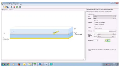
By these reactive loading approaches one can modify the resonant mode of the patch. This also indicates the use of single feed for both the frequencies on a single radiating element. Finally the length and position of the slots can be changed to obtain the microstrip patch antennas resonating at more than one frequency. The final optimized dimensions for the multi band operation of the antenna as shown in Fig 1 are given in the Table 1.
Available online:
https://edupediapublications.org/journals/index.php/IJR/
P a g e | 917(b )
Fig 1: (a) Layout of the Multi band Antenna structure (b) Substrate View of the Proposed Design
PARAMETERS DIMENSIONS
L1 28 mm
L2 16 mm
L3 8 mm
L4 4 mm
L5 9 mm
W1 45 mm
W2 2 mm
W3 19.3 mm
W4 2.7 mm
W5 2 mm
Wg 61 mm
Lg 50 mm
Table 1: Optimized Dimensions of the Multi band Antenna
Available online:
https://edupediapublications.org/journals/index.php/IJR/
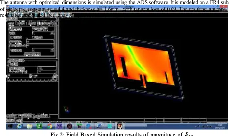
P a g e | 918The antenna with optimized dimensions is simulated using the ADS software. It is modeled on a FR4 substrate of dielectric constant 𝜖𝑟 = 4.4 and thickness h= 1.6mm with tangent loss of 0.09. The resulting antenna resonates at required frequency ranges as shown in Fig 2.
Fig 2: Field Based Simulation results of magnitude of ,
Thus the proposed antenna provides effective control of the two operating bands. In addition, ground plane dimensions can also be optimized to achieve the desired multi band operation, as it affects the resonant frequencies and operating band widths in different bands.
It can be noted that the return loss are small enough for the intended mobile Bluetooth ,WiMAX ,WLAN , 5G based communication systems.
Various other characteristics of the simulated Dual-Band Rectangular microstrip Antenna are given in Table 2.
P A R A M E T E R S S P E C I F I C A T I O N S
R e s ona nc e F r e que nc y 2.44 GHz 2.852GHz 4.143GHz 5.958G Hz 8.46GHz
R e tur n los s -24.71 -28.477 -13.23 -16.033 -16.473
V S W R 0.87 0.84 0.87 0.84 0.92
Gain 5.24 dB
D ir e c tivity 5.25 dB
D im e ns ion 45 mm x 28 mm
Available online:
https://edupediapublications.org/journals/index.php/IJR/
P a g e | 919Table 2: Characteristics of the Simulated Antenna design
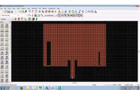
(b) Fig 3: Designed Microstrip Antenna - (a) Momentum simulation window,
(b) Current Distribution of the Antenna
(a)
Available online:
https://edupediapublications.org/journals/index.php/IJR/
P a g e | 920IV.CONCLUSIONS
The object of this work was to design an antenna which can support the modern mobile Communications and analyse various parameters such as its loss characteristics, gain, and radiation pattern The antenna gave acceptable performance just enough to support the proposed structure, but performance of the antenna can be improved over successive optimization and fine tuning of the microstrip design. The future work is to fabricate the prototype and to study its performance.
REFERENCES
[1] Pourghorban Saghati, Mohammadnaghi Azarmanesh, And Reza Zaker (2015) , “A Novel Switchable Single - And Multifrequency Triple-Slot Antenna For 2.4-Gh z Bluetooth, 3.5-Gh z W imax, And 5.8-Gh z Wlan” , IEEE Antennas And Wireless Propagation Letters, Vol. 9.
[2] Yeonsik Yu,1,2 Giho Kim,1 Wonmo Seong,1 And Jaehoon Choi2 (2015), “An Internal Multiband Antenna With Zeroth-Order Resonator For USB Dongle Applications” , Microwave And Optical Technology Letters, Vol. 52, No. 10.
[3] R. Zhan g, Y. Liu, H.H. Kim And H. Kim (2014), “Bandwidth Enhancement Of Ground Antenna Using Resonant Feeding Circuit”, Electronics Letters Vol. 49, No. 7.
[4] J.-H. Lu and B.-J. Huang (2015), “Planar Mu lti-Band Monopole Antenna with L-Shaped Parasitic Strip for Wimax Application”, Electronics Letters Vol. 46 No. 10
[5] Yahya S. H. Khraisat and Ahmad H. N. Qubaia (2015), “Reconfigurable Antenna Desig n, Piers Proceedings, Prague”, Czech Republic Vol. 6.
[6] www.wimaxforu m.co m [7] www.keysightechnologies.com
[8] Salo men, P. and H. Hurme (2014), “Modeling of a fabric GPS antenna for wearable applications,” Proceedings of IASTED International Conference Modeling and Simulation, Vol. 1, pp.18–23.