H
UNIVAC
9700
System
Processor
Programmer Reference
ST=E~y...JL
-,r
L.JNIVAC.
{OMPUTE~
SYSTEMSThis document contains the latest information available at the time of publication. However, the Univac Division reserves the right to modify or revise its contents. To ensure that you have the most recent information, contact your local Univac Representative.
UN I VAC is a registered trademark of the Sperry Rand Corporation. Other trademarks of the Sperry Rand Corporation in this publication are:
UNISCOPE
7936 UP·NUM BER Part/Section Cover/Disclaimer PSS Contents 1 2 ! 3 4 5 6 *New pages Page Number 1
1 thru 7
1 2 thru 6 6a 7 thru 9 10 11
1 thru 3 4 thru 12 13,14 14a 15, 16 16a 17, 18 19thru21 22 23,24 25,26 27 thru 30 31 32 33 34 thru 41
1 thru 3 4 4a 5,6 6a 7,8 8a 9 thru 11 12 13 thru 22 23,24 24a 25 thru 27 28 thru 30 30a 31 thru 37
1 2 3,4 4a 5 6 thru 15
1 thru 19
1 thru 15
Update Level C C C Orig. C C* C Orig. C C Orig. C C* C C* C Orig. C Orig. C Orig. C Orig. C Orig. Orig. C C* C C* C C* Orig. C Orig. C C* Orig. C C* Orig. C Orig. C C* C Orig. Orig. Orig.
UNIVAC 9700 SYSTEM
PAGE STATUS SUMMARY
ISSUE: Update C to UP-7936
Part/Section Page Update Number Level
Appendix A 1 C
2 thru 7 Orig. 8 thru 10 B
Appendix B 1 thru 3 Orig.
Index 1 thru 11 C
User Comment Sheet
Total: 189 pages
including covers
C PSS 1
PAGE REVISION PAGE
Part/Section Page Number
7936
UNIVAC 9700 SYSTEM
C Contents 1U F.NUMBER PAGE REVISION PAGE
CONTENTS
PAGE STATUS SUMMARY
CONTENTS
1.
INTRODUCTION
1.1. GENERAL 1-1
1.2. FUNCTIONAL DESCRIPTION 1-2
1.2.1. Arithmetic Section 1-3
1.2.1.1. GENERAL PURPOSE REGISTEt=tS 1-3
1.2.1.2. FLOATING·POINT REGISTERS 1-3
1.2.1.3. WORKING REGISTERS 1-4
1.2.2. I/O Section 1-4
1.2.2.1. MULTIPLEXER CHANNEL 1-4 ~
1.2.2.2. SELECTOR CHANNEL 1-5
1.2.3. Main Storage 1-5
1.2.4. Control Storage 1-6 ~
1.3. CONFIGURATION 1-6
1.3.1. Processor 1-6
1.3.2. Operator Console 1-10
2.
ARITHMETIC SECTION
2.1. GENERAL 2-1
2.2. REGISTERS 2-2
2.2.1. General Registers 2-2
2.2.2. Floating-Point Registers 2-2
2.2.3. Working Registers 2-2
2.2.4. Current Relocation Registers 2~2
2.3. INFORMATION FORMATS 2-4
2.3.1. Datatformats 2-5
2.3.1.1. FIXED-POINT NUMBERS 2-5
2.3.1.2. FLOATING-POINT NUMBERS 2-5
2.3.1.3. DECIMAL NUMBERS 2-6
7936 UP.NUMBER
UNIVAC 9700 SYSTEM
2.3.2. Instruction Formats
2.3.2.1. REGISTER TO REGISTER (R R)
2.3.2.2. REGISTER TO INDEXED STORAGE (RX) 2.3.2.3. REGISTER TO STORAGE (RS)
2.3.2.4. STORAGE AND IMMEDIATE OPERAND (SI) 2.3.2.5. STORAGE TO STORAGE (SS)
2.4. PROGRAM STATUS WORD FORMATS 2.4.1. System Mask
2.4.2. System Mode And Mode Extension
2.4.3. Processor Storage Protection and Relocation Key 2.4.4. I nterrupt Code/Mode Extension
2.4.5. Instruction Length Code 2.4.6. Program Mask
2.4.7. Instruction Address
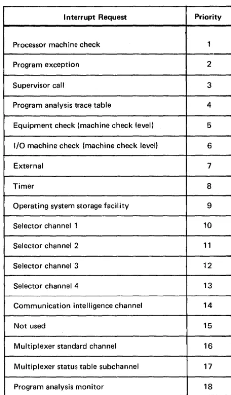
2.5. INTERRUPTS
2.5.1. Interrupt Initialization Sequence (liS) 2.5.2. Interrupt Request and Handling Priority 2.5.3. Address Stored in Old PSW
2.5.4. Nonrecoverable Errors 2.5.5. Machine Check Level
2.5.5.1. INPUT/OUTPUT MACHINE CHECK CLASS 2.5.5.2. PROCESSOR MACH INE CHECK CLASS 2.5.5.3. EQUIPMENT CHECK CLASS
2.5.6. Program Exception Level 2.5.7.
2.5.8. 2.5.9.
Program Analysis Level Supervisor Call Level External Level 2.5.10. Timer Level
2.5.11. Input/Output Channel Levels 2.5.12. Processor Stall Check 2.5.13. Power Control Faults 2.5.14. Program Exceptions
2.5.15. Instruction Termination and Suppression
2.6. 2.6.1. 2.6.2. 2.6.3.
STATUS HANDLING Initial Status Word Channel Status Word Tabled Status Word 2.6.4. Status Word Format 2.6.5. Status Table Subchannel
2.6.5.1. TABLED STATUS WORD
2.6.5.2. HARD STATUS TABLE CONTROL WORD 2.6.5.3. STATUS TABLE CONTROL WORD
2.6.5.4. STATUS TABLE HARD CHANNEL ADDRESS WORD 2.6.5.5. STATUS TABLE CHANNEL STATUS WORD
2.6.5.6. STATUS TABLE SUBCHANNEL INITIALIZATION
C Contents 2
PAGE REVISION PAGE
7936
UNIVAC 9700 SYSTEM
C Contents 3U P-NUMBE R PAGE REVISION PAGE
3.
INPUT/OUTPUT SECTION
3.1. GENERAL 3-1
3.1.1. Channel/System Functional Interface 3-1
3.1.1.1. I/O INTERFACE 3-1
3.1.1.2. INSTRUCTION INTERFACE 3-2
3.1.1.3. MAIN STORAGE INTERFACE 3-2
3.1.1.4. I/O INTERRUPT INTERFACE 3-2
3.1.2. I/O Channel Addressing 3-2
3.1.3. I/O Channel Address Assignments 3-2
3.1.4. I/O Channel Priority 3-3
3.1.5. I/O Channel Interrupt Priority 3-4
3.2. MULTIPLEXER CHANNEL 3-4
3.2.1. Subchannels 3-4
3.2.1.1. STANDARD SUBCHANNEL 3-4
3.2.1.2. DATA COMMUNICATION SUBSYSTEM SUBCHANNELS 3-5
3.2.2. Device Addresses 3-5
3.2.3. Status Handling 3-7
3.2.4. Polling 3-7
3.2.5. Channel Register Stack 3-7
3.3. SELECTOR CHANNEL 3-8a
3.3.1. Device Addresses 3-9
3.3.2. Status Handling 3-9
3.4. CHANNE L PROGRAMMING 3-10
3.4.1. Command Chaining 3-10
3.4.2. Data Chaining 3-11
3.4.3. Transfer in Channel 3-13
3.4.4. Input Buffer Skipping 3-13
3.4.5. Relocation in I/O 3-13
3.4.6. I/O Interface Error Snapshot 3-14
3.5. CHANNEL TESTER 3-16
3.5.1. Functional Characteristics 3-16
3.5.2. Command Codes 3-17
3.5.3. Mode Byte 3-18
3.5.4. Status Byte 3-19
3.5.5. Sense Byte 3-20
3.5.6. Initial Selection Sequence 3-21
3.5.7. Control Unit Busy Sequence 3-21
3.5.8. Data and Status Transfers 3-22
3.5.9. Selective Reset Sequence 3-23
3.5.10. System Reset Sequence 3-23
3.5.11. Interface Disconnect 3-23
3.5.12. Command Chaining 3-23
3.6. INPUT/OUTPUT CONTROL 3-23
3.6.1. Channel Address Word 3-23
3.6.2. Hard Channel Address Word 3--24
3.6.3. Channel Command Word 3-25
3.6.4. Hard Channel Command Word 3-28
7936
UNIVAC 9700 SYSTEM
C Contents 4UP.NUMBER PAGE REVISION PAGE
3.7. TIMERS 3-32
3.7.1. Stall Timer 3-32
3.7.2. Interval Timer 3-32
3.8. TIMER CONTROL WORDS 3-32
3.8.1. Hard Timer Control Word 3-33
3.8.2. Timer Control Word 3-34
3.8.3. Timer Hard Channel Address Word 3-35
3.8.4. Timer Channel Status Word 3-35
3.8.5. Timer Subchannel Initialization 3-37
4.
MAIN STORAGE
4.1. GENERAL 4-1
4.2. INFORMATION POSITIONING 4-1
4.3. FIXED STORAGE ASSIGNMENTS 4-3
4.4. PARTIAL WRITE 4-4a
4.5. STORAGE PROTECTION 4-4a
4.5.1. Storage Key 4-4a
t
4.5.2. Storage Protection and Rei ocation Key 4-54.5.3. Key Comparison 4-5
4.5.4. Summary of Storage Protection Rules 4-5
4.6. ADDRESSING 4-6
4.6.1. Address Relocation 4-7
4.6.1.1. ABSOLUTE AND RELATIVE ADDRESSES 4-7
4.6.1.2. CHARACTERISTICS OF ADDRESS RELOCATION 4-8
4.6.1.3. RELOCATION REGISTER FORMAT 4-8
4.6.1.4. LOADING CURRENT RELOCATION REGISTER 4-9
4.6.1.5. INSTRUCTION ADDRESS RELOCATION 4-10
4.6.1.6. OPERAND ADDRESS RELOCATION 4-11
4.6.1.7. INPUT/OUTPUT ADDRESS RELOCATION 4--11
4.6.2. Indirect Addressing 4-11
4.6.2.1. INDIRECT ADDRESS CONTROL WORD 4-12
4.6.2.2. STORAGE PROTECTION - IACW REFERENCES 4-13
4.6.2.3. INDIRECT ADDRESSING OPERATION 4-13
4.7. PRIORITY ASSIGNMENTS 4-14
4.8. MAIN STORAGE ERRORS 4-14
4.8.1. Address Check 4-14
4.8.2. Addressing Exceptions 4-15
4.8.3. Storage Parity Checks 4-15
4.8.4. Storage Hold Check 4-15
7936
UNIVAC 9700 SYSTEM
C Contents 5UP.NUM BER PAGE REVISION PAGE
5.
SYSTEM CONSOLE
5.1. GENERAL 5-1
5.2. SUBSYSTEM COMPONENTS 5-2
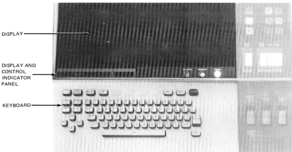
5.2.1. Keyboard/Display 5-2
5.2.1.1. DISPLAY AND CONTROL INDICATOR PANEL 5-2
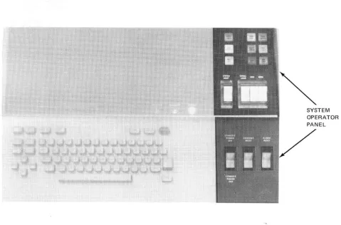
5.2.2. System Operator Panel 5-3
5.2.3. System Console Control Unit 5-3
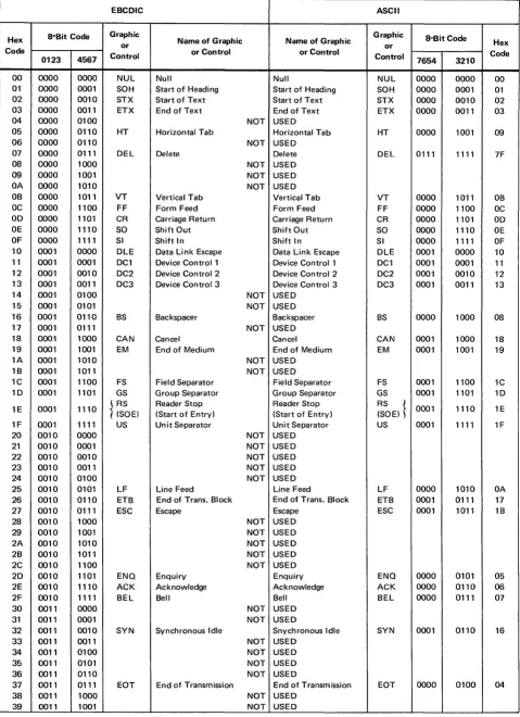
5.2.3.1. CONTROL UNIT TRANSLATION CODES 5-3
5.3. CONTROLS AND INDICATORS 5-11
5.3.1. Keyboard and System Control Switches and Indicators 5-11
5.3.1.1. DISPLAY CONTROL AND INDICATOR PANEL 5-11
5.3.1.2. POWER CIRCUIT BREAKER 5-16
5.3.1.3. SECURITY SWITCH 5-16
5.3.2. Power Distribution Panel 5-16
5.3.3. Power Control Panel 5-18
5.3.4. Logic Test Panel 5-19
6.
INCREMENTAL PRINTER
6.1. GENERAL 6-1
6.2. CHARACTERISTICS 6-1
6.2.1. Physical Characteristics 6-2
6.2.2. Printing Characteristics 6-3
6.3. FUNCTIONAL DESCRIPTION 6-3
6.3.1. Ink Rollers 6-3
6.3.2. Printwheel and Print Hammer 6-4
6.3.3. Incremental Carriage Movement 6-4
6.3.4. Paper Feed 6-5
6.3.5. Requirements for Printed Forms 6-8
6.3.6. Character Codes 6-12
6.3.7. Character Sequence 6-13
6.4. CONTROLS AND INDICATORS 6-13
6.4.1. Operator Control Panel 6-13
6.4.2. Power Control Panel 6-14
6.4.3. Power Supply 6-15
APPENDIXES
A.
INSTRUCTIONS
B.
GLOSSARY
INDEX
USER COMMENT SHEET
FIGURES
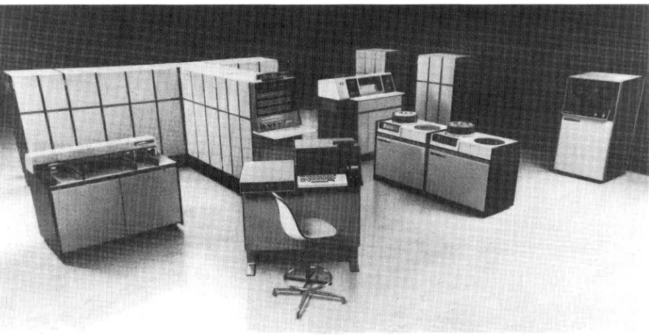
1-1. UN IV AC 9700 System 1-1
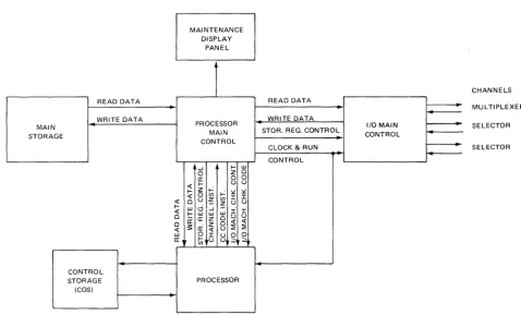
1-2. UNIVAC 9700 Processor, Functional Block Diagram 1-2
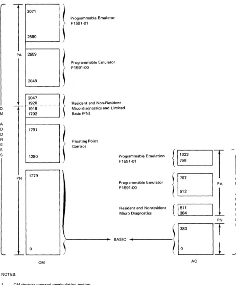
1-2A. Control Storage Map 1-6a ~
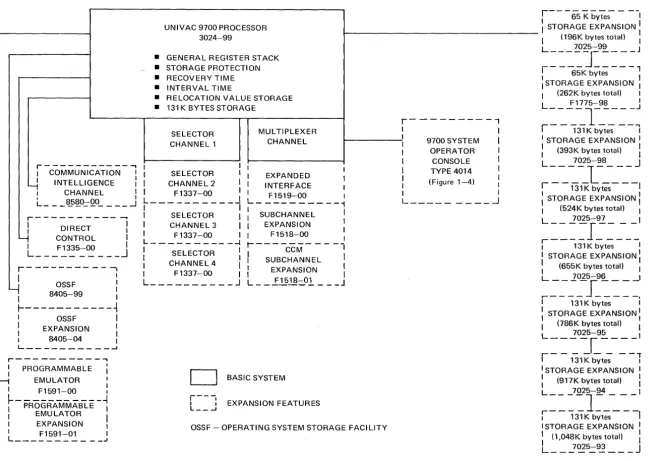
1-3. System Configuration for UN IV AC 9700 Processor 1-7
7936
UNIVAC 9700 SYSTEM
UP-NUMBER
2-1. Processor Registers 2-2. Information Formats 2-3. Instruction Formats
3-1. Multiplexer Channel - Channel Register Stack (CRS)
4-1. Fixed Main Storage Assignments
5-1. UNIVAC 9700 Operator Console
5-2. UN IVAC 9700 Operator Console Keyboard and Display 5-3. UNIVAC 9700 Operator Console System Operator Panel 5-4. UN IVAC 9700 Operator Console, Controls and Indicators 5-5. Display Control and Indicator Panel
5-6. Operator Console Power Distribution Panel 5-7. Operator Console Power Control Panel 5-8. Operator Console Logic Test Panel
6-1. UN IVAC 0722 Receive-Only Incremental Printer 6-2. Printing Mechanism
6-3. Printer Carriage
6-4. Carriage Return Time for Print Positions 6-5. Paper Supplied from Input Hopper 6-6. Paper Loaded in Printer
6-7. Continuous Form Design
6-8. ASCII-Based Code Used on Printer 6-9. Operator Control Panel
6-10. Power Control Panel
A-1. Basic Instruction Formats (Object Code Form)
TABLES
1-1. Optional Features
1-2. UNIVAC 9700 System Console, Basic Components and Optional Features
2-1. Interrupt Levels
2-2. Interrupt Request Handling Priority
3-1. I/O Channel Storage Priority 3-2. I/O Channel Interrupt Priority 3-2A. Multiplexer Channel Configurations 3-3. Subchannel/Device Address Correspondence 3-4. Channel Programming Operation
3-5. Command Codes for Channel Tester
5-1. Control Unit Translation Codes, EBCDIC to ASCII 5-2. Control Unit Translation Codes, ASCII to EBCDIC 5-3. Operator Console Keyboard Controls and Indicators
5-4. Operator Console Power Distribution Panel, Controls and Indicators 5-5. Operator Console Power Control Panel Controls
6-1. Printer Physical Characteristics 6-2. Printing Characteristics 6-3. Print Wheel Character Set 6-4. Continuous Form Requirements
C Contents 6
PAGE REVISION PAGE
7936
UF.NUMBER
UNIVAC 9700 SYSTEM
6-5. Paper Thickness and Weight
6-6. Cut Versus Uncut Dimensions on Forms 6-7. Operator Control Panel, Controls and Indicators 6-8. Power Control Panel, Controls and Indicators
A-1. Symbols Used to Describe Op Code Formats A-2. Alphabetical List of Instructions
A-3. List of Instructions by Op Code A-4. I nstruction Execution Times A-5. Legend for Table A-4
C Contents 7
FAGE REVISION PAGE
6-11 6-11
6-14
...-6-15
7936
UNIVAC 9700 SYSTEM
1-1UP.NUMBER PAGE REVISION PAGE
I. INTRODUCTION
1.1.
GENERAL
This reference contains the information for programming the UN IVAC 9700 System (Figure 1·1). It describes the internal operation of the processor, main storage, and the I/O channels. The formats of the system status and control words are detailed. Also provided is a brief description of the optional features available for expansion of the processor and main storage.
The UNIVAC 9700 System consists of a processor, console, expandable plated·wire main storage, one multiplexer channel, up to four selector channels, and UNIVAC 9000 Series byte·oriented peripheral devices. Information pertaining to individual peripheral devices may be obtained from their respective programmer and operator references.
Appendix A lists machine instructions with their associated hexadecimal operation (op) code. The instructions are in alphabetical order according to instruction name. Also listed are the five instruction·type formats. A detailed description of these codes and instructions is given in the UNIVAC 9700 System OS/4 Assembler Programmer Reference, UP·7935 (current version).
Appendix B, the glossary, is an alphabetic listing of all mnemonics described in this reference.
7936
UNIVAC 9700 SYSTEM
c
UP-NUMBER PAGE REVISION PAGE
1.2. FUNCTIONAL DESCRIPTION
The UNIVAC 9700 Processor (processor) is a medium scale, microprogrammed, general purpose processor that may be used for commercial, scientific, or real time data processing. The processor operates in word parallel with a repertoire of fixed-point binary, hexadecimal floating-point, decimal, arithmetic, logical, status switching and branching instructions. It has a flexible and safe storage protection scheme. Comprehensive storage relocation and protection, with eight levels of indirect addressing algorithm, provide dynamic relocation and rollin/rollout of portions of the operating software and user (worker) programs.
One multiplexer channel and up to four selector channels permit the attachment of a wide variety of control units and peripheral devices. Main storage has a minimum capacity of 131 K bytes, expandable to more than 1048K bytes.
The two basic types of internal processor operations are the data path logic, which is data manipulations; and control, which is control signal generation. The I/O channel operates as an independent data handling system which operates in parallel with the processor.
The processor operates under microprogram control and contains a recovery timer, storage protection, and register stack. Microprogramming refers to the technique whereby certain logic functions, such as incrementing the instruction address field of the current program status word, accessing the instruction operands in storage and general registers, and fetching the next instruction, are controlled by series of microinstructions. These microinstructions are located in the control storage (COS) which is a storage medium dedicated to the microprogram. A microprogram actually controls the execution of all program instructions. Figure 1-2 illustrates the basic functions of the processor and its interrelationship with all essential data and control paths.
MAINTENANCE DISPLAY
PANEL
CHANNELS
READ DATA READ DATA
MULTIPLEXER
WRITE DATA
PROCESSOR WRITE DATA
MAIN 1/0 MAIN
MAIN STOR. REG. CONTROL CONTROL STORAGE
SELECTOR
CONTROL
CLOCK & RUN SELECTOR
CONTROL
-l ~ Ul
0 Z 0
a: 0 0
« l- t ) t )
I- Z ~ ~ -:i -:i « 0 C/)
:r: :r:
t ) ~ C/)
« 0 z t) t )
I- Ul <3 -l
-:i -:i
« !: Ul Ul Ul 0 a: z 0 t) t ) 0 a: z 0 « «
« :: ci « t) ::2 ::2 Ul 0 :r: ~.g 0 a: ~ l- t ) :;
C/)
CONTROL
STORAGE PROCESSOR
(COS)
Figure 1-2. UNIVAC 9700 Processor, Functional Block Diagram
7936
UNIVAC 9700 SYSTEM
c
UP_NUMBER PAGE REVISION PAGE
1.2.1. Arithmetic Section
The arithmetic section performs all logical operations, arithmetic operations, data comparisons, and shifting. Fixed-point binary arithmetic uses twos complement number representations. Floating-point arithmetic and decimal arithmetic use signed absolute-value number representation. The arithmetic section also performs single and double indexing of operand addresses, together with address relocation and indirect addressing. This section contains a register stack comprised of:
• General purpose registers
• Floating-point registers
• Working registers
1.2.1.1. GENERAL PURPOSE REGISTERS
A register stack contains the general registers in two sets of 16 each. These registers can be used for fixed-point arithmetic, logical operations, and the indexing (except register) of instructions and operand addresses.
• Fixed-Point Arithmetic
Fixed-point numbers have a fixed, predetermined binary point (or power) and are held in the twos complement form. When the sign bit is set to 1, the integer represents a negative value; when the sign bit is 0, the integer represents a positive value. When held in one of the 16 general registers, a fixed-point number is generally treated as a 32-bit operand. When a half-word fixed-point number is called from main storage and loaded into a register, the sign is extended to the left to fill the full-word register. The contents of the register are then handled as a full-word operand in fixed-point arithmetic operations.
Double-word operations use a 64-bit operand consisting of one sign bit followed by a 63-bit integer field. The 64-bit operand is located in two adjacent general registers, and it is addressed by an even address referring to the lower-numbered register of the pair.
When fixed-point data is located in storage, it may be stored as a half word, full word, or double word. This data must be located on the integral storage boundary of its associated format.
• Logical Operations
Logical operations such as comparing, translating, editing, bit setting, and bit testing are also performed by the arithmetic section of the processor on data stored in the general purpose registers or in main storage and the results are placed back into the general purpose registers or main storage.
1.2.1.2. FLOA TlNG-POINT REGISTERS
1-3
Four floating-point registers are available. Each floating-point register has a capacity of 64 bits to accommodate ~
either the short format (one word) or the long format (one double word). A short operand occupies the high order bit positions of the register. The low order half of the register is ignored and remains unchanged in short precision floating-point operations.
7936
UNIVAC 9700 SYSTEM
c
UP-NUMBER PAGE REVISION PAGE
1.2.1.3. WORKING REGISTERS
Decimal arithmetic operations are performed in eight working registers. Decimal number fields can be variable in length and can exist in two formats: packed decimal numbers and unpacked decimal numbers.
The packed decimal format is used for all decimal arithmetic operations. In the packed format, each byte contains two digits. The least significant four bits of the least significant byte provides the sign of the number.
In the unpacked decimal format, each byte contains one digit of a multidigit number. The byte is divided into two equal fields: zone and digit. A zone value is represented in the most significant four bits, and the digit is represented in the least significant four bits. The zone portion of the least significant byte specifies the sign of the number. The unpacked format must be used when data is to be processed by certain I/O devices, such as
a
printer.Instructions are provided for converting decimal numbers from packed to unpacked and from unpacked to packed format.
1.2.2.
I/O SectionThe I/O section initiates, directs, and monitors the transfer of data between main storage and the peripheral subsystems. After the I/O instruction has been initiated, the data transfer is performed concurrently with other processor functions. The I/O section contains multiplexer and selector channels that have a standard UN IVAC 9000 Series I/O interface.
1.2.2.1. MUL TlPLEXER CHANNEL
The mUltiplexer channel controls the transfer of data between the processor or main storage and I/O subsystems. Connections between the mUltiplexer channel and the I/O subsystems are by way of the 8-bit compatible I/O interface. When an operation is initiated, the channel maintains control of data transfers between the I/O subsystem and main storage. This control allows the processor to proceed concurrently with I/O operations.
Basic characteristics of the multiplexer channel are:
• Up to 175-KB transfer rate.
• One to two UNIVAC 9000 Series compatible interfaces, each with eight drops.
• Up to 63 subchannels.
• Elaborate error detection and reporting capability.
• Complete command and data chaining capability.
There are two types of subchannels associated with I/O operations: standard and data communication. The multiplexer channel is able to distinguish between these two types of subchannels by the format of the device address presented to the channel during an I/O instruction or by way of a request initiated by the control unit.
The multiplexer channel can operate in either the mUltiplex mode or the control-unit-forced-burst mode. In multiplex mode, the channel facilities are shared by a number of concurrently operating I/O devices, with the I/O interface being assigned to a control unit only long enough to transfer one byte of data. Upon completion of this data exchange, the I/O interface is assigned to another control unit requesting service, and the operation proceeds in a similar manner. In the control-unit-forced-burst mode, the control unit stays connected to the I/O interface until as many bytes of data as required for the duration of the operation are transferred. Termination is accomplished either by the channel having the byte count expire or by the control unit.
7936
UNIVAC 9700 SYSTEM
c
1-5UP-NUMBER PAGE REVISION PAGE
1.2.2.2. SELECTOR CHANNEL
One selector ch.annel is provided with the basic system configuration; three additional selector channels are available as optional features. Eight standard control units may be attached to each selector channel. Up to 16 I/O devices can be attached to each of the eight control units, depending on the particular subsystem selected. The devices attached to a selector channel are serviced on a burst mode (one-at-a-time) basis; that is, once transfer of data is initiated between a particular device and main storage, that transfer must be completed before another device on that channel can transfer data.
Because a subchannel is required to maintain data transfer with only one subsystem at a time, there is only one subchannel in the selector channel. Thus, the channel and subchannel in the selector channel may be considered to be identical entities. Also, another I/O device may be executing a previously initiated 'operation which does not require communication with the channel such as rewinding a tape. An operation may be terminated by either the channel or the control unit; thus, the selector channel is free to monitor requests for status presentation from another I/O device or another processor instruction. Basic characteristics of the selector channel are:
• UN IVAC 9000 Series compatible interface • Up to 1, 111-KB transfer rate
• Up to four selector channels
• Complete command and data chaining capability
1.2.3.
~ainStorage
The main storage consists of high speed plated wire. Main storage is contained in freestanding cabinets with a
600-nanosecond read or write cycle time for a full word (2.3). Minimum storage size is 131,072 bytes expandable to ~
a maximum main storage size of 1,048,576 bytes. Addresses and data are checked for odd parity. Each main storage cabinet is equipped with seven address switches. These switches are used as the seven most significant bits of the 24-bit cabinet starting address. If it becomes necessary to place a 131,072-byte storage offline, the switches on the cabinet with the highest addresses can be set to the starting address of the cabinet removed from service. The remaining online cabinets then can have sequential addresses. Only the three lower switches are used for the cabinet starting address. The remaining four top switches are not used but are provided to accommodate expansion beyond 1048K main storage.
Basic characteristics of main storage are: Characteristic
Type of storage Capacity
Description Plated wire
131,072 bytes (minimum) 196,608 bytes
262,144 bytes 393,216 bytes 524,288 bytes 655,360 bytes 786,432 bytes 917,504 bytes
7936
UNIVAC 9700 SYSTEM
c
UP-NUMBER PA GE RE VISION PA GE
t
Characteristic
Cycle Time
Operating Modes Storage Data Path
Checking
1.2.4. Control Storage
Description
600 nanoseconds to read or write one word (four bytes). 600 nanoseconds to write either one, two, or three bytes. Nondestructive read/write.
36 bits wide; consisting of four bytes (where a byte is defined as eight bits) plus a parity bit associated with each byte. The state of the parity bit is such that the parity of the 9 bits (byte plus parity bit) is odd.
Storage protection, write or read/write. (The storage protection check is performed in the processor.)
Address and data parity.
Nonexistent main storage location is referenced.
Control storage is the hardware element that holds the microinstructions microprogrammed for control logic. It is a high speed nondestructive read/write storage (RWM). The COS consists of two independent and separately addressable sections: an address calculation (AC) section, and an operand manipulation (OM) section. Each section contains a program nonalterable (PN) memory and a program alterable (PA) memory. The former type of memory is utilized to store the basic instruction set and floating-point microinstructions while the PA type memory is used to store microdiagnostics, programmable emulators, etc.
A map of the COS is shown in Figure 1-2A.
1.3. CONFIGURATION
The configurations and optional features for the processor and the operator console are described in the following paragraphs.
1.3.1. Processor
The configuration for the processor is shown in Figure 1-3. The solid-line boxes define the basic components, and the dashed-line boxes define the optional features available.
The optional features available for the processor are listed and described in Table 1-1.
UNIVAC 9700 SYSTEM
C 1-6a 7936UP-NUMBER PAGE REVISION PAGE
a
M A D D R E S S PA PN 3071 2560 2559 2048 2047 1920r
--1919 1792 1791 1280 1279l
Programmable Emulator F1591-01
Programmable Emulator F1591-00
Resident and Non-Resident Micordiagnostics and Limited Basic (PNI
Floating Point Control
Programmable Emulation F1591-01
Programmable Emulator F1591-00
Resident and Nonresident Micro Diagnostics
{1~~~3
IT
{I~!
I
PN
o
BASIC~"
--1
T
383
OM AC
NOTES:
1. OM denotes operand manipulation section
2. AC denotes address calculation section
3. PN denotes program nonalterable
4. PA denotes program alterable
5. OM address is out of bounds at OM address 2048
10 if F1591-00 is not installed and at 256010 if F1519-01 is not installed.
6. AC address is out of bounds at AC address 512
10 if F1591-00 is not installed and at 76810 if F1519-01 is not installed.
Figure 1-2A. Control Storage Map
r---,
I COMMUNICATION I I INTELLIGENCE :
I CHANNEL I
, 8580-00 I
L _ _ _ _ -_ _ _ _ _ _ _ .J
r---o
~
DIRECT~
Y
CONTROL II F1335-00 I
L __________
J
r - - - ---.
I I
-I
OSSF :I 8405-99 I
~---
- ----i
I OSSF I
: EXPANSION :
I 8405-04 I
L _ _ _ _ _ _ _ _ _ _ ..J
r---,
: PROGRAMMABLE ;
EMULATOR I
I F1591-00
~
~
- PROGRAMMABLE -~
I EMULATOR
I
I EXPANSION I
I F1591-01 I
L ___________ .J
r - - -
--I 65 K bytes I UNIVAC 9700 PROCESSOR3024-99
1 STORAGE EXPANSION I
t - - - -
1 (196K bytes total) :L 7025-99 J
• GENERAL REGISTER STACK • STORAGE PROTECTION • RECOVERY TIME • INTERVAL TIME
• RELOCATION VALUE STORAGE • 131 K BYTES STORAGE
r - - - ,
I I
SELECTOR CHANNEL 1
MULTIPLEXER
CHANNEL
t---::
9700 SYSTEM 1I OPERATOR I
I CONSOLE I
I TYPE 4014 I
: (Figure 1-4) :
I I
L _ _ _ _ _ _ _ _ _ ...J
I I
I SELECTOR I
1 CHANNEL 2 I
1 F1337-00 I
L __________
J
I I
I SELECTOR I
I CHANNEL 3 I
I F1337-00 I
L - - ________ -I
: SELECTOR :
I CHANNEL 4 1
I F1337-00 I
L __________ J
I I
I EXPANDED I
I INTERFACE I
I F1519-00 I
L - - - 1
I
I SUBCHANNEL I
I EXPANSION I
I F1518-00 :
t
-I CCM I
I SUBCHANNEL I
I
EXPANSION :L __ .£.l?18=..°l ___ J
D
BASIC SYSTEMr---.
L __
J
EXPANSION FEATURESOSSF - OPERATING SYSTEM STORAGE FACILITY
Figure 1-3. System Configuration for UNIVAC 9700 Processor
----I--- ----I--- ----I--- ----I--- ----I---
---,
: 65K bytes I STORAGE EXPANSION: I (262K bytes total) I
L __ ":~75=-9~ ___
J
r - - _ _
1 __ --.,
I 131 K bytes I I STORAGE EXPANSION I : (393K bytes total) :L 7025-98 I
----1---r - -
i3ii<
byi;s-- - I: STORAGE EXPANSION: I (524K bytes total) I
L
----r----
7025-97 Ir - - - -
-I 131 K bytes I I STORAGE EXPANSION: : (655K bytes total) I
L
----1----
7025-96 Ir-
-'31K
b~t~ - - - j: STORAGE EXPANSION:
I (786K bytes total) I
7025-95
L _ _ _ _ [ _ _ _ _ I
, -
-
-
- -
-
--.
I 131 K bytes I I STORAGE EXPANSION I : (917K bytes total) : L
----1----
7025-94 Ir - - - ,
I 131 K bytes I I STORAGE EXPANSION I I (1,048K bytes total) :
L __
~<E5.=~
___
J
C -..J 1) <.0
Z
~7936
UNIVAC 9100 SYSTEM
C 1-8UP.NUMBER PAGE REVISION PAGE
Feature/Type
Name Description
Number
F1335-00 Direct Control Provides a special interface between the 9700 processor and another central processing unit (for example, another 9700 processor) equipped with the same or compatible capability, plus two instructions for transfer of control information, and generation of external interrupts.
F1337-00 Selector Channel Provides a 1.11 megabyte (833-KB) channel with up to 8-subsystem capability. I ncludes channel programming and main storage protection. Maximum of three F1337-00 per system. (Maximum of four selector channels including basic.) Selector channel 2 housed in processor cabinet. Channel expansion cabinet (type 1916-00) is prerequisite to house selector channels 3 and 4.
F1591-00 Programmable Provides programmable control for emulation of: IBM 1401, Emulator 1440, and 1460 programs; Series 70 301 and 501 programs,
and Series 70 mode programs.
*F1591-01 Programmable Provides programmable control, using special hardware Emulator instructions, for concurrent operation of any two of the Expansion emulators listed under F1591-00 which is prerequisite
to this feature.
F1519-00 Expanded interface Expands multiplexer channel interface to provide up to 15-subsystem capability (up to 16 subsystems if F1518-00 is installed).
F1518-00 Subchannel Expands the number of subchannels per multiplexer channel
Expansion to 31.
*F1518-01 Communications Expands the number of subchannels per multiplexer channel Controller to 63 by providing 32 additional subchannels. F 1518-00 Multichannel (CCM) (subchannel expansion) and type 0973-00 (standard interface Subchannel adapter) are prerequisites to this feature.
Expansion
8405-99 Operating System Includes a special channel, control, and one disc file (type Storage Facility 8405-04) with a minimum of 3 million bytes of direct access
storage. Average latency is 8.34 milliseconds. May be expanded by up to seven additional disc files (type 8405-04).
8405-04 Operating System Provides 3 million bytes additional direct access storage to the Storage Facility operating system storage facility. Average latency is 8.34
Expansion milliseconds.
8580-00 Com mu n icati 0 ns Provides a flexible, communications dedicated, input/output
Intelligence channel.
Channel
7025-99 Storage Expansion Provides additional 65,536 bytes of main storage. Expands -65K main storage from 131,072 bytes to 196,608 bytes.
F1775-98 Storage Expansion Provides additional 65,536 bytes of main storage. Expands -65K main storage from 196,608 bytes to 262,144 bytes.
7025-98 Storage Expansion Provides additional 131,072 bytes of main storage. Expands - 131K main storage from 262,144 bytes to 393,216 bytes.
t
*Feature or type is utilized in UNIVAC 9700/Series 70 mode of operation7936
UNIVAC 9700 SYSTEM
C 1-9UP-NUMBER PAGE REVISION PAGE
Feature/Type
Name Description
Number
7025-97 Storage Expansion Provides additional 131,072 bytes of main storage. Expands -196K main storage from 393,216 bytes to 524,288 bytes.
7025-96 Storage Expansion Provides additional 131,072 bytes of main storage. Expands - 262K main storage from 524,288 to 655,360 bytes.
7025-95 Storage Expansion Provides additional 131,072 bytes of main storage. Expands - 131 K main storage from 655,360 bytes to 786,432 bytes.
7025-94 Storage Expansion Provides additional 131,072 bytes of main storage. Expands - 131K main storage from 786,432 bytes to 917,504 bytes.
7025-93 Storage Expansion Provides additional 131,072 bytes of main storage. Expands - 131K main storage from 917,054 bytes to 1,048,576 bytes.
4014-00/01 System Console Provides operator controls, CRT display with entry keyboard.
0772-00/01 Console Printer Provides hard copy printing of selected console output data at up to 30 characters per second.
2519-00/01 Multi-Channel Provides one 2 x 1 switch and space for up to six switches Switch (MCS) for switching a subsystem or subsystem string between two
UNIVAC 9000 Series I/O channels.
F1541-00 MCS Expansion Provides one additional 2 x 1 switch to type 2519. Up to five of these switches may be added to type 2519.
* Featu re or type is uti! ized in UN I V AC 9700/Series 70 mode of operation
t
7936
UNIVAC 9700 SYSTEM
1-10UP·NUMBER PAGE REVISION PAGE
1.3.2. Operator Console
The minimum operating configuration for the UNIVAC 9700 System Operator Console (operator console) consists of a modified UNISCOPE 100 Display Terminal, an operator panel, and a control unit (Figure 1-4).
Optional features avaiJable for the UN IVAC 9700 System Console (system console) consist of the console printer, channel adapter, and multi-channel switch (MCS) control. These features are listed in Table 1-2.
9700 PROCESSOR MULTIPLEXER
CHANNEL
OPERATOR CONSOLE
TYPE 4014
• KEYBOARD/VIDEO DISPLAY
• SYSTEMS OPERATOR PANEL
• CONTROL UNIT
- - - 1
9000 CHANNEL ADAPTER
F1001
J---___ ,--____
....I _ _ _ _ _ _ ..Jr - - - ----,
I
I
I
CONSOLE PRINTERI
l
TYPE 0772l
~----~---~
~
BASICUNIT,-
--,
~
_ -.J
OPTIONAL FEATURESr---,
: MULTI-CHANNEL SWITCH
I
I
CONTRO L (MCS)I
II
TYPE 2519I
I
I
f---I
I
I
II MCS EXPANSION II
(UP TO 5)
I
I
I
F1541I
L ____________
..J
7936
U P.NUMBER
Feature/Type Number
£0 Hz 50 Hz
4014-00 4014-01
0772-00 0772-01
F1001-01 F1001-01
2519-00 2519·01
F1541-00 F1541-00
UNIVAC 9700 SYSTEM
CPAGE REVISION PAGE
Name Description
Operator Console
Console Printer A cabinet providing a printer mechanism and control, power, cooling, and interface to the system operator control. The printer has the full 94-character ASCII set plus space and is capable of printing at a 3D-character· per-second rate.
9000 Channel This feature provides for the control and transfer of Adapter data between the UNIVAC 9700 System channel and
one of the following UN IVAC systems: 9200, 9200 II 9300,9300 II, and 9400.
Multi-Channel A freestanding cabinet containing one basic 2 x 1 Switch (MCS) switch and providing power and space for up to five Control F 1541-00 switches. Operator control is provided in a
separate housing located on top of the console. One switch assembly is supplied with provisions for five additional switches at the operator console panel. The MCS permits a subsystem or series of sub-systems to be switched (statically) between I/O channels on the same or different UN IV AC 9000 Series processors.
Multi-Channel Provides expansion of one additional switch for the Switch Expansion multichannel switch control.
(MCSE)
Table 1-2. UNIVAC 9700 System Console, Basic Components and Optional Features
7936
UNIVAC 9700 SYSTEM
c
2-1UP.NUMBER PAGE REVISION PAGE
2. ARITHMETIC SECTION
2.1. GENERAL
The arithmetic section of the UNIVAC 9700 Processor (processor) is comprised of two independent sections: the
address calculation (AC) section and the operand manipulation (OM) section. Each section is part of the control ~
storage and has an associated address, output, and decoding logic. These sections can operate independently and in parallel to each other.
READ CLOCK & RUN
DATA ,.
READ DATA .... ....
",,-WRITE I/O MULTIPLEXER ...
I I I I I I
l
MAIN STORAGE ... DATA CONTROLS
..
- CONTRoL-STI)I~-;,GE - - - - "I
~---~ I
I
ADDRESS AC MICRO· SUPPORT I
I STATIr ADDRESS REG I DECODE AC CONTROL READ OUTPUT REG I
STORAGE
~
__
...JI+-...t. OM CONTROL
STORAGE
+-- +-- +-- +--
-DATA'" SENSE SYSTEM I CONS~~~~~ATE I CONTROLS
I ... I WRITE DATA CONTROL I ADDRESS I
"'II" I
ADDRESS OM MICRO·
SUPPORT ," I STATIC READ ... I DECODE
ADDRESS REG DATA ... OUTPUT REG I
SENSE SYSTEM I ... CONCATENATE
I CONTROLS ... SYSTEM
- - -
_ _ _ _ _ ..JPROCESSOR MAIN CONTROL ... WRITE DATA SECTION &
(MAIN
~ ~IQEl8~, El,~ 10. CONTROL ~ SELECTOR
CONTROLS CHANNELS
CHANNEL 10.
INSTRUCTION
ARITHMETIC SECTION
ADDRESS CALCULATION STATICIZE
OPERAND FETCH/STORE PSW
INTERRUPTS INTEGRATED
--
GENERAL--REGISTERS OPERAND MANIPULATION
INSTRUCTION EXECUTION
The AC section contains the hardware for the performance of instruction staticizing, operand fetch and storeback, maintenance of the program status word (PSW), and interrupt processing to include the interrupt initialization sequence (I is).
7936
UNIVAC 9700 SYSTEM
c
UP.NUMBER PAGE REVISION PAGE
The splitting of the arithmetic section into two sections allows staticizing of the next instruction to be overlapped with the completion of the execution of the current instruction. Also, operand fetches of a storage-to-storage (SS) instruction are overlapped with the execution.
2.2. REGISTERS
The processor contains a register stack with a capacity of 48 words. This stack contains three types of registers: general, floating point, and working. One additional software identifiable register called the current relocation register is in the arithmetic section but is not part of the register stack. See Figure 2-1 for processor register allocations.
2.2.1.
General Registers
The processor can address one of the two sets of general register stacks (supervisor and problem) under control of
~ the PR (bit 18) of the current program status word (PSW, 2.4). Each stack contains 16 registers that may be used for indexing, fixed·point arithmetic, logical operations, and temporary storage. Each register has a capacity of 32 bits. The registers are addressed by particular 4-bit fields in the instruction being executed by the processor.
Certain instructions use a double-word operand which is held in two adjacent registers. The register address in the instruction field must be an even number. The register pair consists of the addressed register and the next higher-numbered register. The even-address register contains the most significant half of the double word, and the odd-address register contains the least significant half of the double word.
2.2.2.
Floating-Point Registers
Four floating-point registers are provided, each having a capacity of 64 bits. They can accommodate either the short format (one word) or the long format (a double word). A short operand occupies the high order bit position of the register. The low order bit positions of the register are disregarded and remain unchanged in short precision floating-point operations.
The floating-point registers are addressed by various 4-bit fields in the instruction being executed. The operation code being executed determines whether a given 4-bit field addresses the floating-point registers or the general registers. The floating-point registers have addresses 0, 2,4,6. Data is in floating-point format.
2.2.3.
Working Registers
Eight working registers are used for temporary storage of operands and intermediate results during decimal arithmetic operations. Each register is 32 bits in length. The registers used are dictated by the operation (op) code; therefore, they are not directly specified in related user-level instructions.
2.2.4.
Current Relocation Registers
The current relocation register is considered the fourth general register. This register is automatically loaded from low order main storage whenever the key in the current PSW is changed. The new key is used as a pointer to access
~ the appropriate relocation register (4.6.1.3). The availability of the relocation address factor in a register accelerates the calculation of the required storage addresses for operand or instruction access. This register provides the original address relocation from the relocation registers located in low order main storage.
7936
UNIVAC 9700 SYSTEM
C 2-3UP.NUMBER PAGE REVISION PAGE
Program Program
Hardware Specified Status
Size Register
Register Register Word
Number Number PR Bit 18
0 0 0 WORD SUPERVISOR
1 1 0 (32 BITS) GENERAL
2 2 0 REGISTERS
3 3 0 (16)
4 4 0
5 5 0
6 6 0
7 7 0
8 8 0
9 9 0
10 10 0
11 11 0
12 12 0
13 13 0
14 14 0
15 15 0
16 0 1 WORD PROBLEM
17 1 1 (32 BITS) (USER)
18 2 1 GENERAL
19 3 1 REGISTERS
20 4 1 (16)
21 5 1
22 6 1
23 7 1
24 8 1
25 9 1
26 10 1
27 11 1
28 12 1
29 13 1
30 14 1
31 15 1
32 0 DOUBLE FLOATING·POINT
33 WORD REGISTERS
34 2 (64 BITS) (4)
35
36 4
37
38 6
39
40 (not directly 32 BITS WORKING
41 specified REGISTERS
42 by program) (8)
43 44 45 46 47
20 BITS CURRENT RELOCATION REGISTER
(1)
7936
UNIVAC 9700 SYSTEM
2-4UP-NUMBER PAGE REVISION PAGE
2.3. INFORMATION FORMATS
Data and instructions are transmitted in single or multiple 8-bit increments called bytes. Up to four bytes of information may be transmitted in parallel between various sections of the system. Instructions are made up of half-word lengths and can be one, two, or three half words long.
A half word is defined as a field containing two consecutive bytes and is basic for the instructions. A word is a field containing four consecutive bytes; a double word is a field containing two words. Figure 2-2 illustrates the various word formats and bit numbering.
Fixed-length fields such as half words, words, and double words are located in main storage on a integral boundary for the unit of information. Instructions must be located on half-word boundaries. An integral boundary is defined as main storage address for a unit of information which is a mUltiple of the length of the unit in bytes, as follows:
Half word (two bytes) - mUltiple of 2
Full word (four bytes) - mUltiple of 4
Double word (eight bytes) - mUltiple of 8
Storage addresses are expressed in binary form within the processor. Integral boundaries for half words, words, and double words are given as binary addresses in which one, two, or three of the low order bits are 0, respectively.
Variable-length fields are not limited to integral boundaries and can start at any byte address.
BYTE
10
J
MSB LSB
HALF WORD
10
MSB LSB
WORD
10
MSB LSB
DOUBLE WORD
10
MSB LSB
7936
UNIVAC 9700 SYSTEM
UP.NUMBER PAGE REVISION PAGE
2.3.1. Data Formats
Data is represented in several different formats, depending on the type of instruction which is to manipulate the data.
2.3.1.1. FIXED-POINT NUMBERS
Fixed-point numbers are represented in one of threee fixed-length formats consisting of one sign bit (bit 0) followed by a binary integer field. When the sign bit is set to 1, the integer represents a negative value; when set to 0, the integer represents a positive value. Negative integers are represented in the twos complement notation.
The half-word, word, and double-word fomats are as follows:
HALF WORD
INTEGER
WORD
1 : 1
INTEGER
DOUBLE WORD
1
L - - - . L . - - -:11
_ _
INT_EGER_---..fO
When held in one of the 16 general registers, a fixed-point number is treated as a 32-bit operand. Certain multiply, divide, and shift operations use a 64-bit operand consisting of one sign bit followed by a 63-bit binary integer field. A 64-bit operand is located in two adjacent registers and is addressed by referring to the even-numbered register of the even/odd pair.
2.3.1.2. FLOA TlNG-POINT NUMBERS
Floating-point numbers are represented in signed magnitude form and have a fixed-length format which is either a word (short format) or a double word (long format). Both formats may be used in storage or in floating-point registers. In either format, the sign bit (bit 0) is the sign of the fraction and bits 1 through 7 are the characteristic. The fraction field in the short form consists of bits 8 through 31; in the long format, it consists of bits 8 through 63 (which represent 6 and 14 hexadecimal digits, respectively).
The characteristic is a biased exponent expressed in excess-64 binary notation. The fraction is expressed as a hexadecimal number having the radix point to the left of the high order fraction digit. The quantity expressed by the full floating-point number is the product of the fraction and the number 16 raised to the power of the characteristic minus 64.
7936
UNIVAC 9700 SYSTEM
UP-NUMBER PAGE REVISION PAGE
The short and long form ats are as follows:
WORD
CHARACTERISTIC (EXPONENT) 0 1
DOUBLE WORD
CHARACTERISTIC (EXPONENT)
7 8
o
1 7 82.3.1_3. DECIMAL NUMBERS
FRACTION (SHORT FORMAT)
31
FRACTION (LONG FORMAT)
D
Decimal numbers are represented in signed absolute form and in either packed or unpacked formats with variable lengths. These are used in decimal arithmetic and logical operations. For decimal operations, the numbers are again processed from data stored in the general purpose registers or in main storage and the results are placed back into the general purpose registers or into main storage, requiring a field area of from 1 to 16 eight-bit bytes.
The packed and unpacked decimal formats are shown as follows:
UNPACKED DECIMAL FORMAT
BYTE 1 (HIGH ORDER)
ZONE DIGIT
PACKED DECIMAL FORMAT
BYTE 1 (HIGH ORDER)
DIGIT DIGIT
2.3.1.4. LOGICAL INFORMA TlON
BYTE 2
ZONE DIGIT
BYTE 2
DIGIT DIGIT
BYTE n (LOWORDER)
SIGN DIGIT
- -
- -
-
-
-
-
-'---_
..._---'
BYTE n (LOW ORDER)
- - - -
-I---~----~DIGIT SIGN
- - - '---_ ... _---1
Logical informat!on is precessed as fixed-length or vadabie-iength data. Operations using this type of information include moving, comparing, translating, editing, bit testing, bit manipulation, and shifting.
Fixed-length data, which consists of one, four, or eight bytes, is processed from data stored in the general purpose register or in main storage and the results are placed back into these registers or into main storage.
Data in the general registers normally occupies all 32 bits. In logical operations, all bits are treated uniformly, with no distinction made between sign and numeric bits. In some operations, only the low order eight bits of a register are used; the remaining 24 bits are unchanged. In some shift operations, all 64 bits of an even/odd pair of registers are used.
7936
UNIVAC 9700 SYSTEM
UP-NUMBER PAGE REVISION PAGE
Logical data in fixed-length format is as follows:
BYTE
BYTE 1
o 7
WORD
BYTE 1 BYTE 2 BYTE 3 BYTE 4
(HIGH ORDER) (LOW ORDER)
0 7 8 15 16 23 24 31
DOUBLE WORD
BYTE 1 BYTE 8
(HIGH ORDER) (LOW ORDER)
t - - - + - - - \ - - - -I----..;.;;;;...;;...;..;..~...;;....;;;..;...;.;.--~
o 78 15 56 63
Variable-length data has up to 256 bytes of alphabetic or numeric character codes (alphanumeric data). This information is again processed from data stored in the general purpose registers or in main storage and the results are placed back into the general purpose registers or into main storage, and occupies fields which may start at any byte address. The processing order of variable length data is from high order (most significant) byte to the low order
(least significant) byte.
Logical data in variable-length format is as follows:
BYTE 1 (HIGH ORDER)
BYTE 2 BYTE 256
(LOW ORDER)
- - - -1---;
o
7 8 15~---~~---~
- - -
-
- -
2040 20477936
UNIVAC 9700 SYSTEM
UP-NUMBER PAGE REVISION PAGE
2.3.2. Instruction Formats
Instructions are identified by an op code field which is the most significant eight bits of the instruction. Two general categories of instructions related to a processor state are available to the programmer:
• Supervisor (Privileged) Instructions
Privileged instructions can be executed only when the processor is in the supervisor mode. The PSW specifies the operating modes of the processor. Processor states may switch as a result of an interrupt condition that causes a new PSW to be obtained from storage or from a load-program-status-word (LPSW) instruction. If the program attempts to execute a privileged instruction, a program exception interrupt occurs. It should be noted that the supervisory routines use the privileged instructions and the problem programmer should avoid these instructions.
• Problem (Nonpriviledged) Instructions
The problem instructions can be executed in either the supervisor or the program mode.
The format used for programmed instructions for directing peripheral devices and processing data may vary in format and length. The format used is dictated by the operation to be performed and the operand location. The length of the instruction is dictated by the format and is either one, two, or three half words.
The five instruction formats are shown in Figure 2-3 and are identified as follows:
Register to Register (R R)
Register to I ndexed Storage (R X)
Register to Storage (RS)
Storage and Immediate Operand (SI)
Storage to Storage (SS)
7936
UNIVAC 9700 SYSTEM
2-9UP.NUMBER PAGE REVISJON PAGE
HALF WORD 1 HALF WORD 2
BYTE 1 BYTE 2 BYTE 3 BYTE 4
HALF WORD 3
BYTE 5 BYTE 6
RR FORMAT
10
OP CODE
71s
R1,,I,,
R2,51
RX FORMAT
10
OP CODE
1
R1,,I,,
X 2,L
B2,L
O2J
RS FORMAT
10
OP CODE
J
R1,t
R;3,L
B2,L
O2-J
SI FORMAT
10
OP CODE
1
'2,L
B1,1
0 1J
SS FORMAT
10
OP CODE L1
,,I,,
L2,L
B1,1
0 1J
7 8
I 1 1
or
it,
8 2J~
O2J
I 1 I
Is
L
J
oref
7936
UNIVAC 9700 SYSTEM
2-10UP-NUM BER PAGE REVISION PAGE
2.3.2.1. REGISTER TO REGISTER (RR)
The R R instruction is one half word in length and has one of the following formats:
OPCODE
0 7 8
where:
Rl/Ml (bits 8-11)
R2 (bits 12-15)
11 (bits 8-15)
R1/M1 R2
11 12 15
or
R 1 specifies the number of a general register or floating-point register which contains the first operand.
Ml represents a mask for the branch-on-condition (SCR) instruction only.
Specifies the number of a general register or floating-point register that contains the second operand_
Represents an 8-bit byte of immediate data.
23.2.2. REGISTER TO INDEXED STORAGE (RX)
The RX instruction is one word in length and has the following format:
OP CODE
0 7 8
where:
RdMI (bits 8-11)
X 2 (bits 12-15)
R1/M1 X 2 8 2 O2
11 12 15 16 19 20 31
R 1 specifies the number of a general register or floating-point register that
contains the first operand. Rl also specifies where the result is to be stored, if required.
Ml specifies the number of a general register that contains an index value in the SCR instruction only.
7936
UNIVAC 9700 SYSTEM
UP.NUMBER PA GE REVISION PAGE
B2 (bits 16·19)
D2 (bits 20-31)
Specifies the number of a general register that contains an index value representing the base address of the second operand. When set to 0, the base address is O.
Contains a 12-bit displacement value that, when added to the contents of B2 and
X
z
and offset (if applicable), represents the address of the second operand. If a load-address instruction is being executed, the final address sum is stored in a general register rather than being used to address main storage.2.3.2.3. REGISTER TO STORAGE (RS)
The RS instruction is one word in length and has the following format:
OP CODE
where:
R 1 (bits 8-11)
R3 (bits 12-15)
R2 (bits 16-19)
D2 (bits 20-31)
Specifies the number of a general register containing the first operand. These bits also specify the general register where the result is to be stored if required. Specifies the number of a general register containing the third operand. This field is ignored when executing the shift instructions.
Specifies the number of a general register that contains an index value representing the base address of the second operand. When B2 is set to 0, the base address is O.
Contains a 12·bit displacement value that, when added to the contents of B2, represents the address of the second operand. For shift instructions, the value of B2 represents the number of bits to be shifted.
2.3.2.4. STORAGE AND IMMEDIA TE OPERAND (SI)
The SI instruction is one word in length and has the following format:
OP CODE
where:
12 (bits 8-15)
Bl (bits 16-19)
Contains the second operand (immediate operand). It may be unused, used for a mask, or used as a secondary operation code.
Specifies the number of a general register that contains an index value representing the base address of the first operand. When Bl is set to 0, the base address is O.
7936
UNIVAC 9700 SYSTEM
UP-NUMBER PAGE REVISION PAGE
Dl (bits 20-23) Contains the 12-bit displacement value that, when added to the contents of B 1
and offset (if required), represents the address of the first operand. For I/O instructions, these bits specify a channel and device number.
Offset is the 12-bit relocation value contained in bits 8-19 of the relocation register located in main storage (4.6.1.3).
2.3.2.5. STORAGE TO STORAGE (SS)
The SS instruction is three half words in length and has one of the following formats:
OP CODE
78
where:
Ll (bits 8-11)
L2 (bits 12-15)
L (bits 8-15)
ef (bits 8-15)
15 16
or
L
or
ef
Contains a 4-bit number that specifies the number of additional bytes in the first operand field to the right of the left-most byte when the instruction contains Fx op codes, for a decimal instruction where x is any hexadecimal digit 0 through
F.
Contains a 4-bit number that specifies the number of additional bytes in the second operand field to the right of the left-most byte for decimal instructions. For instructions '"ft.,'ith Dx op codes (:ogical SS instructions)' where x is any hexadecimal digit 0 through F; Ll and L2 are combined as L to form an 8-bit number that specifies the number of additional bytes to the right of the operand address for both operands, with the exception of translate, translate-and-test, edit, and edit-and-mark instructions, in which case L applies to the first operand only.
For the emulation-aid instruction, the second byte of the instruction is used for a secondary operation code.
7936
UNIVAC 9700 SYSTEM
CUP-NUMBER PAGE REVISION PAGE
B1 (bits 16-19)
D1 (bits 20-31)
B2 (bits 32-35)
D2 (bits 36-47)
Specifies the number of a general register that contains an index value representing the base address of the first operand. When these bits are set to 0, the base address is O.
Contains a 12-bit displacement value that, when added to B1 and offset (if required), represents the address of the left-most (high order) byte of the first operand.
Specifies the number of a general register that contains an index value representing the base address of the second operand. When these bits are 0, the base address is O.
Contains a 12-bit displacement value that, when added to the contents of B2 ,
represents the address of the left-most (high order) byte of the second operand.
2.4. PROGRAM STATUS WORD FORMAT
The program status word (PSW) is a double word containing the next instruction address and various control fields which establish operating modes, specify the protection and relocation key, hold program branching conditions, and assist in analyzing interrupt causes. The running program is under control of a PSW which is stored in the processor and is called the current PSW. The format of the PSW is as follows:
P M X T
x C
0 1 2 3
ILC
r
"r
SYSTEM MASK
R S S D 1 2
4 5 6
PROGRAM MASK
S S 3 4
7 8
\ /
C SI P
C A R E 9 10
M M M X X S S T T 0
11 12 13 15 SYSTEM
MODE
A W
16 17 P R
18
INTERRUPT CODE/ \ / K E Y , r-MODE EXTENSION " \
P S
19 20 23 24 31
INSTRUCTION ADDRESS
\
2-13All or part of the PSW may be loaded into the current PSW register by use of instructions and interrupts. An entire ~
PSW may be loaded into the current PSW register either by the processor accepting an interrupt or executing a load-PSW instruction. The 13 bits of the system mask may be loaded separately by means of the set-system-mask (SSM) instruction. The six bits of the program mask field may be loaded by means of the set-program mask (SPM) instruction. The I LC, CC, and instruction address fields of the PSW are continually updated, depending on the instructions being executed. The low order 32 bits of the current PSW may be stored by executing the branch-and-I ink instructions.
2.4.1. System Mask
7936
UP.NUMBER
UNIVAC 9700 SYSTEM
c
PAGE REVISION PAGE
t
The individual mask bits are defined as follows:
PX (bit 0) Program exception level interrupt mask
MC(bit1) Machine check level interrupt mask
X (bit 2) External level interrupt mask
TO (bit 3) Timer level interrupt mask
RO (bit 4) Operating system software facility level interrupt mask (I/O channel 6)
Sl (bit 5) Selector channell level interrupt mask (I/O channell)
S2 (bit 6) Selector channel 2 level interrupt mask (I/O channel 2)
S3 (bit 7) Selector channel 3 level interrupt mask (I/O channel 3)
S4 (bit 8) Selector channel 4 level interrupt mask (I/O channel 4)
CIC (bit 9) Communications intelligence channel level interrupt mask (I/O channel 5)
(bit 10) Spare (reserved for I/O channel 7)
MUX STO (bit 11) Multiplexer channel - standard subchannel level interrupt mask (I/O channel 0)
MUX ST (bit 12) Multiplexer channel - status table subchannel level interrupt mask (I/O channel 0)
2.4.2. System Mode and Mode Extension
The seven bits of the mode field (bits 13-19 of the PSW) and the eight bits of the mode extension field (bits 24-31 of the PSW) are uSid to establish various operating modes of the processor. The first three bits of the mode field (bits 13 through 15) are designated the M field and are coded to specify one of 5 mutually exclusive special modes of operation. The remaining bits (bits 16 through 19) may occur in any combination along with any mode specified by the first three bits. The codes 011, 110, and 111 are undefined and should not be used. The use of any of the undefined codes produces indeterminate results. The interpretation of the various other bits in the mode field is as follows:
7936
UNIVAC 9700 SYSTEM
C 2-14aUP-NUMBER PAGE REVISION PAGE
• M Field
Field Code
Mode Use
(Bits 13, 14, 15)
000 UNIVAC 9700 native This is the normal operating mode of the UNIVAC 9700 mode processor in the absence of any other mode. Interrupt
processing and instruction sequencing may be modified per the setting of the mode extension field of the current PSW.
001 UNIVAC 9400 com- Used to modify the operation of certain instructions in patibility mode the repertoire to facilitate the running of programs
written for the UNI V AC 9400 System. I nterrupt processing and instruction sequencing may be modified per the setting of the mode extension field of the current PSW.
010 Special compatibility Specification of this mode results in an operation exception interrupt request to be generated if the following instructions are attempted while in this mode: EA, AI, BALE, BCRE, and LBR. Interrupt processing and instruction sequencing can be modified per the setting of the mode extension field of the current PSW.
100 Special emulation Following the completion of the operation that establishes mode I this mode (LPSW or UNIVAC 9700 liS), the processor
suspends the fetching and execution of instructions in the normal manner. Microprogram control is transferred to the program alterable (PA) portion of the operand manipulation (OM) section of control storage by setting the OM address register to 2048
10. Thereafter each time the address calculation (AC) microprogram starts the OM with op code, the most significant OM address register bit (bit 0) is set to 1, thus causing the reference to be made at or above location 2048
10. In a similar manner, each time the OM microprogram starts the AC portion of control storage with Start Staticize, the most significant AC address register bit (bit 0), is set to 1 causing the reference to be made at or above AC location 512
10.
This operation continues so long as the current PSW indicates that the processor is in this mode. This mode would typically be used for emulation of functions (or macros) that are very different from UNIVAC 9700 native mode functions.
101 Special emulation Following the completion of the operation that establishes mode II this mode (LPSW or UNIVAC 9700 liS), normal fetching of <