Volume 2008, Article ID 574784,12pages doi:10.1155/2008/574784
Research Article
A Design Framework for Scalar Feedback in
MIMO Broadcast Channels
Ruben de Francisco and Dirk T. M. Slock
Eurecom Institute, BP 193, 06904 Sophia-Antipolis Cedex, France
Correspondence should be addressed to Ruben de Francisco,[email protected]
Received 15 June 2007; Revised 6 October 2007; Accepted 13 November 2007
Recommended by Markus Rupp
Joint linear beamforming and scheduling are performed in a system where limited feedback is present at the transmitter side. The feedback conveyed by each user to the base station consists of channel direction information (CDI) based on a predetermined codebook and a scalar metric with channel quality information (CQI) used to perform user scheduling. In this paper, we present a design framework for scalar feedback in MIMO broadcast channels with limited feedback. An approximation on the sum rate is provided for the proposed family of metrics, which is validated through simulations. For a given number of active users and aver-age SNR conditions, the base station is able to update certain transmission parameters in order to maximize the sum-rate function. On the other hand, the proposed sum-rate function provides a means of simple comparison between transmission schemes and scalar feedback techniques. Particularly, the sum rate of SDMA and time division multiple access (TDMA) is compared in the following extreme regimes: large number of users, high SNR, and low SNR. Simulations are provided to illustrate the performance of various scalar feedback techniques based on the proposed design framework.
Copyright © 2008 R. de Francisco and D. T. M. Slock. This is an open access article distributed under the Creative Commons Attribution License, which permits unrestricted use, distribution, and reproduction in any medium, provided the original work is properly cited.
1. INTRODUCTION
Multiple-input multiple-output (MIMO) systems can sig-nificantly increase the spectral efficiency by exploiting the spatial degrees of freedom created by multiple antennas. In point-to-point MIMO systems, the capacity increases lin-early with the minimum of the number of transmit/receive antennas, irrespective of the availability of channel state in-formation (CSI) [1,2]. In the MIMO broadcast channel, it has recently been proven [3] that the sum capacity is achieved by dirty paper coding (DPC) [4]. However, the applicability of DPC is limited due to its computational complexity and the need for full channel state information at the transmitter (CSIT). Downlink techniques based on space division mul-tiple access (SDMA) have been proposed [5], achieving the same asymptotic sum rate as that of DPC.
The capacity gain of multiuser MIMO systems is highly dependent on the available CSIT. While having full CSI at the receiver can be assumed, this assumption is not reasonable at the transmitter side. Several limited feedback approaches have been considered in point-to-point systems [6–8], where
each user sends to the transmitter the index of a quantized version of its channel vector from a codebook. An exten-sion for MIMO broadcast channels is made in [9], in which each mobile feeds back a finite number of bits regarding its channel realization at the beginning of each block based on a codebook.
[15,16], respectively. The total amount of feedback overhead in the system can be reduced by appropriately setting mini-mum desired SINR thresholds while controlling each user’s quality of service (QoS). A performance comparison of sev-eral scalar metrics for scheduling is provided in [17] for sys-tems with zero-forcing beamforming (ZFBF) transmission.
In this paper, we present a design framework for scalar feedback in MIMO broadcast channels, which generalizes previously proposed techniques. A family of metrics is pre-sented based on individual SINRs, which are computed at the receivers and fed back to the base station as channel quality information. The framework here presented can be applied to any system in which codebooks are employed for channel direction quantization. Moreover, additional orthogonality constraints between beamforming vectors may be considered with the purpose of simplifying the task of user scheduling and controlling the amount of multiuser interference.
An approximation on the ergodic sum rate is provided for the proposed family of metrics. The resulting sum-rate function fits well the simulated sum rate as shown through simulations, even in cells with reduced number of active users. This function, as we show, can be a powerful design tool and at the same time it greatly simplifies system anal-ysis. On the one hand, we can envisage a cellular system in which, given certain average SNR conditions and number of active users, the base station sets the different parameters so as to maximize the sum-rate function. On the other hand, as shown in the analysis, the sum-rate function provides a means of simple comparison between different transmission schemes and scalar feedback techniques in extreme regimes, without the need of extreme value theory. Particularly, we compare the sum rate of SDMA and TDMA approaches in scenarios with large number of users, high SNR, and low SNR regimes. Simulations are provided to illustrate the per-formance of different scalar feedback techniques based on the proposed design framework.
The paper is organized as follows.Section 2introduces the system model. Linear beamforming with limited feed-back is introduced inSection 3, presenting system assump-tions on codebook design, beamforming design, and user scheduling. Design guidelines for scalar feedback are given inSection 4and the corresponding sum-rate function is pro-vided inSection 5.Section 6shows a comparison of SDMA and TDMA in different extreme regimes, namely, large num-ber of users, high SNR, and low SNR.Section 7shows nu-merical results and conclusions are drawn inSection 8.
2. SYSTEM MODEL
We consider a multiple antenna broadcast channel consisting ofMantennas at the transmitter andK≥Msingle-antenna receivers. The received signalykof thekth user is mathemat-ically described as
yk=hHkx+nk, k=1,. . .,K, (1)
where x ∈ CM×1 is the transmitted signal,h
k ∈ CM×1 is an i.i.d. Rayleigh flat fading channel vector, andnk is addi-tive white Gaussian noise at receiverk. We assume that each
of the receivers has perfect and instantaneous knowledge of its own channelhk, and thatnkis independent and identi-cally distributed (i.i.d.) circularly symmetric complex Gaus-sian with zero mean and varianceσ2 = 1. The transmitted
signal is subject to an average transmit power constraintP, that is,E{x2} =P. Note that, since unit-variance noise is
assumed,Ptakes on the meaning of average SNR. LetS de-note the set of users selected for transmission at a given time slot, with cardinality|S| =Mo, 1≤Mo≤M. Letvkbe the unit-norm beamforming vector for userk. Assuming equal power allocation to theMoscheduled users, the received sig-nal at thekth mobile is given by
yk=
P Mo
i∈S
hHkvisi+nk, k=1,. . .,K. (2)
Hence, the SINR of userkis
SINRk=
hH kvk
2
i∈S,i=khHkvi2+Mo/P
. (3)
We focus on the ergodic sum rate (SR) which, assuming Gaussian inputs, is equal to
SR=E k∈S
log1 + SINRk . (4)
Notation: We use bold upper and lower case letters for ma-trices and column vectors, respectively. (·)Hstands for Her-mitian transpose.E(·) denotes the expectation operator. The notation xrefers to the Euclidean norm of the vectorx, and∠(x,y) refers to the angle between vectorsxandy.
3. LINEAR BEAMFORMING WITH LIMITED FEEDBACK
Joint linear beamforming and scheduling are performed in a system where limited feedback is present at the transmitter side. The feedback conveyed by each user to the base station consists of channel direction information based on a prede-termined codebook and a scalar metric with channel quality information used to perform user scheduling.
In such systems, the design of appropriate scalar metrics in scenarios with realistic number of users and average SNR values remains a challenge. These metrics must contain in-formation of the users’ channel gains as well as channel quan-tization errors, as discussed in [18]. If the users have addi-tional knowledge of the beamforming technique used at the transmitter side, an estimate on the multiuser interference at the receiver can be computed. This information can be en-capsulated together with the channel gain, quantization er-ror, and average noise power into a scalar metricξ, which consists of an estimate on the SINR. In our work, we con-sider such scalar feedback strategies, as discussed in detail in next section. User selection is carried out based on these met-rics and the users’ spatial properties, obtained from channel quantizations.
MS
Compute&Feedbackξk
quantization indexi∈ {1,. . .,L} BS
InitializeSetS=∅
LoopFori: 1,. . .,Morepeat Setξimax=0
LoopFork: 1,. . .,K,k∈Srepeat Ifξk> ξimaxand|vHkvj| ≤∀j∈S
ξk→ξ i
maxandki=k Selectki→S
Algorithm1: Outline of scheduling algorithm.
of users scheduled for transmission. The normalized chan-nel vector of userkto be quantized ishk =hk/hk, which corresponds to the channel direction. AB-bit quantization codebook Vk is considered, containing L = 2B unit norm vectors inCM, which is assumed to be known to both the re-ceiver and the transmitter. Similar to [7,8], we assume that each receiver quantizes its channel to the vector that maxi-mizes the inner product
vk=arg max
v∈Vk
hHkv
2
=arg max
v∈Vk
cos2∠
hk,v
. (5)
Each user sends the corresponding quantization index back to the transmitter through an error-free and zero-delay feed-back channel usingBbits. Note that this model is equivalent to the finite rate feedback model proposed by [7,9].
The optimal vector quantizer is difficult to find and the solution to this problem is not yet known. As codebook de-sign goes beyond the scope of the paper, we adopt the ge-ometrical framework presented in [8]. The resulting quan-tization error is defined as sin2θk =sin2(∠
hk,vk)) =1−
|hHkvk|2[8,19], wherevkis the quantized channel direction of userk. Using this framework, the cumulative distribution function (cdf) of the quantization error is given by [8,19],
Fsin2θ k(x)=
δ1−MxM−1, 0≤x≤δ,
1, x > δ, (6)
whereδ=2−B/(M−1).
Let the orthogonality factordenote the maximum de-gree of nonorthogonality between two unit-norm vectors. The columns of the normalized beamforming matrixV(S) are constrained to be-orthogonal and thus
vH
i vj≤ ∀i,j∈S, i=j. (7)
An outline of the proposed scheduling algorithm is shown inAlgorithm 1. In caseMo users with-orthogonality can-not be found, the algorithm stops and distributes the power equally among the scheduled users, settingMo = |S|. Note that this greedy algorithm is equivalent to the one proposed in [5,20,21]. The first user is selected from the set Q0 =
{1,. . .,K}as the one having the highest channel quality, that
is,k1 =arg maxk∈Q0ξk. Fori =1,. . .,Mo−1, the (i+ 1)th
user is selected aski+1 = arg maxk∈Qiξk among the user set
Qi= {1≤k≤K:|vH
kvkj| ≤, 1≤j≤i}.
The number of active beams for transmissionMoand or-thogonality factoris system parameters fixed by the base station (BS) that can be adapted in order to maximize the system sum rate.
4. SCALAR FEEDBACK DESIGN
In this section, we present design guidelines for scalar met-rics based on signal-to-interference-plus-noise ratios, which are computed at the receivers and fed back to the base station as channel quality information. Complemented with channel quantizations as CDI, user scheduling at the base station of a MIMO broadcast channel is performed. The design frame-work for scalar feedback here presented can be applied to any system in which codebooks are employed for channel quan-tization, known both to the base station and mobile users.
These metrics must contain information of different na-ture in order to exploit the multiuser diversity of the MIMO broadcast channel. Moreover, additional information on the orthogonality constraints between beamforming vectors can be taken into account, thus providing a QoS estimate at the receiver side. The total amount of feedback overhead can be reduced by appropriately setting minimum desired SINR thresholds. Hence, in a practical system each user may send feedback to the base station only if a minimal QoS can be guaranteed.
Besides signal and noise power, the following informa-tion may be encapsulated by each user in such scalar metrics:
(i) channel power gain:hk2, (ii) quantization error: sin2θk, (iii) orthogonality factor:, (iv) number of active beams:Mo.
As shown in [18], channel power gain and quantization er-ror information are necessary in order to exploit the avail-able multiuser diversity. The quantization error is a function of the number of codebook bits, as shown in the previous section. By increasing the codebook size, the multiplexing gain of the system can be increased (better resolution) and at the same time the multiuser diversity gets increased, due to lower quantization error. The orthogonality factorcan be used to bound the amount of expected multiuser interfer-ence, which in turn can be used to compute a lower bound on the SINR. In our work, we assume that the number of ac-tive beams (nonzero power) is a parameter appropriately set by the base station to maximize the system sum rate.
Multiuser interference
For user k and index set S, the multiuser interference can be expressed as Ik(S) =
which returns the largest eigenvalue. DefineIUBkas the upper
bound on Ik and θk = ∠(hk,vk). As proven in [18] for systems with arbitrary orthogonality between beamforming vectors, the multiuser interference of userkcan be bounded as follows:
IUBk=αkcos 2θ
k+βksin2θk+ 2γksinθkcosθk, (8)
where
αk=vHkΨkvk,
βk=λmax
UHkΨkUk
,
γk=UH kΨkvk.
(9)
Family of metrics
In the proposed design framework, any scalar feedback met-ric can be described as follows:
ξ= hk2cos2θk
hk2 αcos2θ
k+βsin2θk+ 2γsinθkcosθk
+Mo/P
.
(10)
The numerator in the expression above reflects the effective received power in a system with channel quantization. On the other hand, the denominator accounts for the noise power and provides a measure of the interference experienced by the user, for instance, an upper or lower bound, by exploit-ing the structure of the beamformexploit-ing matrix. By choosexploit-ing different values for the parametersα,β,γ, andMo, the mean-ing of the proposed metric is modified, yieldmean-ing different SINR measures. In next section, a sum-rate function is de-rived based on this metric structure, for arbitrary values of these parameters. When setting these parameters as in (9), the metricξbecomes a lower bound for the SINR described in (3). Note that, even though-orthogonality beamformers are imposed at the transmitter, we may choose not to include this information in the scalar feedback metric. In addition, even thoughMois in principle a parameter that may be mod-ified by the base station, a simplmod-ified case withMo=Mmay be considered for feedback design.
In the remainder of this section we present several scalar metrics complying with this structure.
Metric 1. Let ujk be the jth column vector of the matrix
Uk. The vectorujk is isotropically distributed over anM− 1 dimensional hyperplane orthogonal to vk, under the as-sumption that vk is isotropically distributed over the unit norm hypersphere. Given a fixed unit-norm vector vi in CM, the random variable |vH
i ujk|
2
follows a beta distribu-tion with parameters (1,M−2) [22]. The mean value of this random variable is 1/(M−1), and thus we have that E[Mo
i=1,i=k|viHujk|2]=(Mo−1)/(M−1). Using this result in (9) and the fact that nonorthogonality between pairs of
beamforming vectors is upper bounded by, we propose in [18] the following values for this metric:
α=
Mo−1
2
M−1
2, β=
Mo−1
M−1
1 +Mo−2
,
γ=
Mo−1
2
M−1 , 1≤Mo≤M.
(11)
Note that averaging the inverse of the resulting metric yields an upper bound on the average of the inverse SINR. Hence, the average value of this metric tends to be a lower bound on the average SINR.
Metric 2. As a particular case, we consider=0 in the metric computation and assume a fixed number of active beams
α=0, β=1,
γ=0, Mo=M. (12)
This metric can be interpreted as an upper bound on the SINR when exactlyMo = M beams are used for transmis-sion and equal power allocation is performed. Note that this metric was proposed in parallel in [12–14].
Metric 3. Another option consists of computing a lower bound on the instantaneous SINR [15]. As opposed to Metric 1, no averaging over the distribution of|vHkuik|is per-formed and thus this lower bound is less tight in average. The metric parameters are given by
α=Mo−1
2,
β=
0, ifMo=1, 1 +Mo−2
, otherwise,
γ=Mo−1
, 1≤Mo≤M.
(13)
Taking into account in the SINR computation may mask the contribution of the channel power gains in the SINR ex-pression, hence reducing the benefits of multiuser diversity. However, this approach offers the advantage of avoiding out-age events in the communication link.
Metric 4. A straightforward improvement ofMetric 2can be done by setting a variable number of active beams 1≤Mo≤
M, keeping the same values forα,β, andγ.
0 2 4 6 8 10 12
S
u
m
ra
te
(b
it
s/s/H
z)
0 0.1 0.2 0.3 0.4 0.5 0.6 0.7 0.8 0.9 1 Alignment
Mo=2
Mo=3
Mo=4
Mo=1
0.8 0.85 0.9 0.95 1 4
4.5 5 5.5 6 6.5 7 7.5 8
Mo=1 Mo=2 Mo=3 Mo=4
Figure 1: Approximated lower bound on the sum rate using
Metric 1versus the alignment cosθk) forM = 4 antennas, vari-able number of active beamsMo, orthogonality factor=0.1 and SNR=10 dB.
out by storing lookup tables at the base station, so that andMocan be quickly adapted whenever the average SNR or the number of active users changes. If the system parame-ters need to be updated, the base station broadcasts the new values to the users, which are used to compute the feedback metrics.
InFigure 1, an approximated lower bound on the sys-tem sum rate is plotted as a function of the alignment cosθk, computed as SR≈Molog (1+ξIk), whereξ
I
kdenotes the feed-back Metric 1 of userk. This approximation assumes that theMoscheduled users have the sameξIkvalue and thus the same estimated lower bound on the achievable rate. The sys-tem under consideration is assumed to haveM =4 anten-nas, = 0.1, and average SNR = 10 dB. The sum rate is evaluated for different number of active beams to observe the impact of appropriately choosingMo. Note that the case ofMo = 1 corresponds to TDMA, whereasMo > 1 corre-sponds to SDMA. The system withMo = 1 exhibits better performance for low and intermediate values of cosθk, that is, TDMA provides higher rates than SDMA in most cases. Only for large values of cosθk,Mo>1 provides higher rates, which in practice occurs for large number of quantization bitsBor large number of usersK. Since the amount of bits
Bis generally low due to bandwidth limitations, SDMA will be chosen over TDMA whenMo>1 users with small quan-tization errors can be found, with higher probability as the number of users in the cell increases. As the parameter in-creases, the crossing points of the curves inFigure 1shift to the right and thus the range for which TDMA performs bet-ter also increases. This is due to the fact that the bound in
ξIk becomes looser for increasingvalues. As shown in this example, for>0 there existMpossible modes of transmis-sion, that is,Mo =1,. . .,M. However, for the case of=0 and varyingMoas considered inMetric 4, it can be proven that the modes of transmission exhibiting higher rates are reduced to 2, namely,Mo=1,M.
5. SUM-RATE FUNCTION
In this section, we derive a function to approximate the er-godic sum rate that a system with linear beamforming and limited feedback can provide, given knowledge of each user’s SINR metric. A general and simple solution is derived based on the generic metric representation ofξ, given in (10). Note that the different metrics described in the previous section follow as particular cases ofξby setting accordingly the val-ues ofα,β,γ, andMo. The sum-rate function we provide is a tool that enables simple analysis and comparison of SDMA and TDMA approaches. Moreover, as shown in the simu-lations, it approximates well the system number even when the number of users in the cell is small. In our analysis, we are interested in the actual sum rate that can be achieved. Hence, the metric takes on the meaning of either an upper or lower SINR bound as needed in order to compare SDMA and TDMA in the extreme regimes under study.
First, an approximation on the cdf ofξis derived, using mathematical tools from [23].
Proposition 1. In the low-resolution regime (smallB), the cdf
ofξcan be approximated as follows:
Fξ(s)≈1− e
−Mos/P(1−αs)
δM−1(1 +m)M−1, (14)
where m = (2γs[γs+ γ2s2+ (1−αs)βs] + (1−αs)βs)/
(1−αs)2.
Proof. SeeAppendix A.
Note that the above cdf is a generalization for arbitrary andMoof the cdf derived in [13]. Also, the result provided in [10] follows as a particular case by selecting=0,Mo=M, andB=0.
Let the ordered variatesi:K denote theith largest among
Ki.i.d. random variables. From known results of order statis-tics [24], we have that the cdf ofs1 =max1≤i≤Ksi:K isFs1 =
(Fξ(s))K. According to the proposed user selection algorithm, the SINR of the first-selected user is the maximum SINR overKi.i.d. random variables. However, at theith selection step (ith beam) the search space gets reduced since the -orthogonality condition needs to be satisfied. Hence, theith user is selected overKii.i.d. random variables yielding a cdf for the maximum SINR given byFsi = (Fξ(s))
Ki. Sinceξ is
upper bounded by 1/α, its mean value is given by
Esi
=
1/α
0 1−
Fξ(s)
Ki
ds. (15)
An approximation ofKican be calculated through the prob-ability that a random vector inCM×1is-orthogonal to a set
withi−1 vectors inCM×1, which is equal toI
2(i−1,M−i+1)
[5],Ix(a,b) being the regularized incomplete beta function. By using the law of large numbers [21], we can find the fol-lowing approximation:
0 1 2 3 4 5 6
Sum
ra
te
(b
p
s/
H
z)
1 0.8
0.6 0.4
0.2 0
3
2
1
Mo
Figure2: Sum-rate function usingMetric 1versus orthogonality factorand number of active beamsMo, forK=35 users, SNR= 10 dB, andB=1 bit.
The average sum rate in a system withMoactive beams can be bounded as follows by using Jensen’s inequality:
SR=
i∈S
Elog21 +si
≤
i∈S
log21 +Esi
. (17)
Using (17) and solving the integral in (15) for the cdf ofξ de-scribed in (14), we obtain the following theorem after some approximations.
Theorem 1. Given-orthogonal transmission in a system with
Moactive beams, the sum rate is approximated as follows:
RMo≈
Mo
i=1
log2
1 + 1
α
Ki
n=1
BnKi,nPn
, (18)
where
Bn=(−1)
n−1 δn(M−1),
Ki,n=
Ki
n
,
Pn=1 +Cn
α e
Cn/αE i
−Cn
α
,
(19)
andC=Mo/P+ (M−1)β. The exponential integral function is defined asEi(x)= −
∞
−x(e−t/t)dt. Proof. SeeAppendix B.
Note that the termBnreflects the influence of the code-book design,Ki,ntogether with the summation upper limit
Kiinside the logarithm capture the amount of multiuser di-versity exploited by the system andPnaccounts for the de-pendency of the sum rate on the power.
Note that as a particular case of the equation above, a simpler expression can be derived forMo=1, given by
R1≈log2
1 +
K
n=1
BnK1,nP
n
. (20)
1 1.5 2 2.5 3 3.5 4 4.5 5 5.5
Sum
ra
te
(b
p
s/
H
z)
0 0.1 0.2 0.3 0.4 0.5 0.6 0.7 0.8 0.9 1
Simulated Analytical
Figure3: Comparison of analytical and simulated lower bounds on the sum rate usingMetric 3, forM=2 antennas,K=15 users, SNR=10 dB, andB=1 bit.
Another case of interest is the case in whichα=0. Asα ap-proaches zero, we have
lim α→0
1
α
1 +Cn
α e
Cn/αE i
−Cn
α
= 1
Cn, (21)
and thus the sum-rate function in this case becomes
lim α→0RMo=
Mo
i=1
log2
1 + Ki
n=1
BnKi,n 1
Cn
. (22)
InFigure 2, the sum-rate function in (18) is plotted as a func-tion of the number of active beamsMoand orthogonality fac-tor, using the values forα,β, andγas described inMetric 1. In this simulation, a system withK=35 users has been con-sidered, an average SNR=10 dB and a simple codebook with
B =1 bit. Note that in this particular scenario, SDMA can-not guarantee better rates than TDMA regardless of the value of. In this context, the number of users is low, hence there is low probability of obtaining large values of cosθk. Thus, TDMA transmission is favored, which is consistent with the results obtained in the previous section.
In order to validate the obtained sum-rate function, we consider a simple scenario withM=2 antennas and a system in which Mo = 2 if 2-ortogonal users can be found in a given time slot andMo=1 otherwise. The probability of not finding 2-orthogonal users is given by p = [1−2]K−1.
Hence, the approximated rate in this simplified scenario is given by
R≈pR1+ (1−p)R2, (23)
where R1 andR2 (RMo with Mo = 2) are as described in
1 2 3 4 5 6 7 8 9 10
Sum
ra
te
(b
p
s/
H
z)
0 0.1 0.2 0.3 0.4 0.5 0.6 0.7 0.8 0.9 1
SNR=0 SNR=10 SNR=20
Figure4: Simulated lower bound on the sum rate usingMetric 3as a function of the orthogonality factorfor largeK.
different from user to user. Note that the jitter in the analyti-cal curve is due to the rounding effect ofKi.
6. STUDY OF EXTREME REGIMES
In this section, we analyze several extreme regimes, namely, scenarios with large number of users, high SNR, and low SNR regime. The results intuitively clarify the cases in which SDMA is better than TDMA and the role ofin the compari-son of both techniques. Previous works in the literature focus on the study of the asymptotic scaling withPorK by using results from extreme value theory, as shown in [10,13]. Here, we base our study on simpler mathematical tools. The ratios between the sum rates provided by SDMA and TDMA are computed in different limiting cases, by using the sum-rate functions derived in the previous section.
6.1. Large number of users
In this subsection, we provide asymptotical results showing that SDMA can provide higher rates than TDMA in near-orthogonal MIMO systems as the number of users increases, which is consistent with the work presented in [25]. First, note that the number of available users at theith step can be bounded asKi ≥K2(M−1)as shown in [5]. For finite SNR, we can easily obtain from (18) and (20) the following result.
Theorem 2. Given an arbitrary, SDMA outperforms TDMA
asymptotically with the number of users
lim K→∞
RMo R1 =Mo.
(24)
Proof. As shown in Figure 3, it can be seen from (18) that
RMo, as function of, is lower bounded byRMo|=1. Thus,
here we focus on a lower bound on the SINR, as described
byMetric 3, in order to provide a lower bound on the actual sum rate. The value=1 results in a pessimistic SINR lower bound in the metric given in (9). Setting =1, we obtain that in each selection stepKi=K−i+ 1,i=1,. . .,Mo, and thus
RMo≥
Mo
i=1
log2
1 + 1
α
K−i+1
n=1
BnK1,nPn
, (25)
wherePn=1 + (C n/ α)eCn/αEi(−C n/ α),C=C|=1,and α= α|=1. Therefore, we get the following lower bound on
the ratio betweenRMoandR1:
lim K→∞
RMo R1
≥ lim K→∞
RMo|=1 R1
(a)
=lim K→∞
Mo
i=1log2
K−i+ 1 (K−i+1)/2
(1/α)B(K−i+1)/2P(K−i+1)/2
log2
K K/2
BK/2(P/K/2)
(b)
= lim K→∞
Mo
i=1log2
K−i+ 1 (K−i+ 1)/2
log2
K K/2
(c)
=Mo,
(26)
where (a) follows from selecting the highest exponent terms ofKin the numerator and denominator and (b) from apply-ing the logarithm property log (xy)=log (x) + log (y), keep-ing the relevant terms for the computation of the limit; (c) follows by realizing that limK→∞(log2(
K−a
(K−a)/2)/log2(K/K2)) =
1 for any finite integera.
Similar to the lower bound obtained onRMo/R1, it can
be shown that limK→∞(RMo/R1)≤Moby assuming an upper
bound on the SINR as metric with 1≤Mo≤M, which cor-responds to the case of usingMetric 4. SettingKi=K−i+ 1,
i=1,. . .,Mo, and using the sum-rate function for the partic-ular case ofα=0, given in (22), yields the desired result.
6.2. High SNR regime
This scenario corresponds to the interference-limited region, in which the multiuser interference limits the system perfor-mance rather than the average SNR. The number of usersK
is considered to be finite in the analysis of this regime.
Theorem 3. Given an arbitrary, TDMA outperforms SDMA
in the high SNR regime
lim P→∞
RMo R1 =
0. (27)
Proof. The bounded behavior of SDMA as function of the powerPis intuitively reflected in the proposed rate function. It suffices to realize that the power dependent part ofRMocan
be upper bounded as follows:
In order to provide a proof for the theorem, we focus here onMetric 4, which yields an upper bound on the SDMA sum rate with variable number of active beams. Since in this case we have thatα = 0, the sum rate is described by (22). The power dependent part is bounded by the following constant:
lim P→∞
1
C =Plim→∞
P
Mo+ (M−1)βP = 1
(M−1)β. (29)
Hence, when transmittingMo>1 active beams, the sum rate is bounded regardless of the transmitted power. Thus we have that
lim P→∞
RMo R1 ≤
lim P→∞
Mo
i=1log2
1 +Ki
n=1BnKi,n(1/Cn)
log21 +Kn=1BnK1,n(P/n)
=0,
(30)
where the inequality follows from the fact that an upper bound on the SDMA sum rate is used, based onMetric 4with
α=0. The equality comes from the fact that when taking the limit, the numerator is not a function ofPas shown in (29). Since bothRMo andR1are greater than or equal to zero, we
obtain the desired result.
Note that the above result is consistent with the work in [9], in which the interference-limited behavior of MIMO broadcast channels is studied in a system where limited feed-back is available in the form of channel direction informa-tion.
6.3. Low SNR regime
This scenario corresponds to the noise-limited region. In this regime, the choice of has an impact on the optimal choice of transmission technique, that is, SDMA or TDMA. In Figure 4we show the evolution of the optimal value of for varying SNR in a cell with large number of users,
K = 1000,M = 2 antennas and a codebook ofB = 1 bit. The simulated system adapts the optimal number of active beams as a function ofso that the lower bound on the sum rate computed on the basis ofMetric 3. Fixing = 0 im-plies that the system forces a TDMA solution since there is zero probability of finding two quantized random channels perfectly orthogonal, assuming different quantization code-books for each user. A shift to the right in the position of the maximum implies that the number of-orthogonal users found at the second step (K2) also increases, hence using 2
beams for transmission and thus exploiting the benefits of SDMA rather than TDMA. Therefore,Figure 4shows that as the SNR decreases, a system based on near-orthogonal trans-mission tends to select SDMA over TDMA.
However, if the system parameteris set independently of the average SNR value (or equivalently the power P for normalized noise power), we obtain the following theorem for finite number of users.
Theorem 4. Given an arbitrary, set independently of SNR,
TDMA provides the same or better performance than SDMA in the low SNR regime:
lim P→0
RMo R1 ≤
1. (31)
Proof. In order to proof the theorem, we first proof the fol-lowing asymptotic relation between SDMA and TDMA in 2 extreme cases:
0≤lim P→0
RMo R1 ≤
1
Mo if=0, (32)
0≤lim P→0
RMo R1 ≤
1 if=1. (33)
First, we note that the relation limP→0(RMo/R1) ≥ 0
fol-lows from the fact that both RMo andR1 are greater than
zero for positiveP. In order to proof the upper bound on limP→0(RMo/R1) for=0, 1, we consider an upper bound on
the sum rate, provided by usingMetric 4. Since in this case
α=0, we use the sum-rate function given in (22). We obtain the following result:
lim P→0
RMo R1
≤lim P→0
Mo
i=1log2
1 +Ki
n=1BnKi,n(1/Cn)
log21 +Kn=1BnK1,n(P/n)
(a)
=lim P→0
Mo
i=1
Ki
n=1
BnKi,n/n
(1/C) 1+Ki
n=1BnKi,n(1/Cn)
1+Kn=1BnK1,n(P/n)
K
n=1
BnK1,n/n
(b)
= 1
Mo
Mo
i=1
Ki
n=1
BnKi,n/n
K
n=1
BnK1,n/n
,
(34)
where (a) follows from applying L’H ˆopital’s rule, with (1/C)=∂(1/C)/∂P=Mo/[Mo+ (M−1)βP]2, and (b) fol-lows from limP→0(1/C)=1/Mo. For the case=0, we have thatK1 = K, andKi = 0 fori ≥ 2. Hence, it can be seen from (34) that the ratio becomes 1/Mo, thus yielding (32). For the case=1, we getKi=K−i+ 1,i=1,. . .,Mo. For simplicity, we provide a looser upper bound by considering
Ki = K−i+ 1, i = 1,. . .,Mo, which yields the result de-scribed in (33). Since intermediate values ofindependent of the SNR will yield values for (34) in the range (1/Mo, 1), we obtain the desired result.
7. NUMERICAL RESULTS
1 2 3 4 5 6 7 8 9 10 11
Sum
ra
te
(b
p
s/
H
z)
0 0.1 0.2 0.3 0.4 0.5 0.6 0.7 0.8 0.9 1
Full CSIT
2nd step of feedback
Computed lower bound
Figure5: Comparison of simulated lower bound on the sum rate usingMetric 3, and actual sum rates obtained with second step of feedback and full CSIT.M =2 antennas,K =10 users, SNR = 20 dB, andB=1 bit.
second step of full CSIT feedback, which means that given a set of users selected for transmission by using Metric 3, the BS requests full channel information from those users to perform transmit matched filtering. We can see that the bound becomes looser as increases, since the bound on the SINR becomes more pessimistic. In the simulated sys-tem withK =10 users, the maximum average sum rate oc-curs when the system sets orthogonality =0. This means that the system forces that at each time slot only one beam will be active, since there is zero probability of finding two quantized random channels perfectly orthogonal, assuming different quantization codebooks for each user. Thus, in the simulated scenario with reduced number of users, TDMA (one active beam per time slot) is the optimal transmission technique while in systems with large number of users SDMA is optimal as shown in previous section.
In the remainder of this section, we compare the ac-tual sum rate achieved by systems based on different scalar feedback: Metrics1,2,3, and4, forM = 3 antennas and
B = 9 bits. For comparison, the performances of random beamforming (RBF) [10] and TxMF with perfect CSIT and exhaustive-search user selection are provided. The systems using Metrics1,2, and4are assumed to appropriately setMo andboth for transmision and metric computation, maxi-mizing the sum rate for eachKand SNR pair. On the other hand, the scheme withMetric 2uses optimalvalues in each scenario.
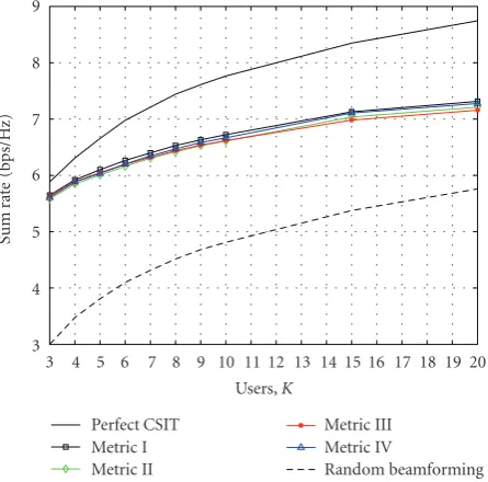
Figure 6shows a performance comparison in terms of sum rate versus number of users for SNR=10 dB, in a cell with realistic number of active users. The scheme based on Metric 1provides slightly better performance than the other schemes. The scheme based onMetric 3exhibits worse scal-ing with the number of users, thus exploitscal-ing less effectively the multiuser diversity. Note that all schemes exhibit slightly worse scaling than RBF and the perfect CSIT solution. This is due to the fact that a simple transmission technique has been
3 4 5 6 7 8 9
Sum
ra
te
(b
p
s/
H
z)
3 4 5 6 7 8 9 10 11 12 13 14 15 16 17 18 19 20 Users,K
Perfect CSIT Metric I Metric II
Metric III Metric IV
Random beamforming
Figure6: Sum rate achieved by different feedback approaches as a function of the number of users, forB =9 bits,M =3 transmit antennas, and SNR=10 dB.
used, TxMF, since beamforming design is beyond the scope of this paper. In order to restore the optimal scaling withK, zero-forcing beamforming (ZFBF) can be performed at the transmitter based on the available channel quantizations, as discussed in [13].
Figure 7depicts the performances of different schemes in the low-mid SNR region, in a setting withK =10 users. As the average SNR in the system increases, the sum rate of schemes using Metrics1and3for feedback converges to the same value. They exhibit linear increase in the high SNR re-gion as expected, which corresponds to a TDMA solution. The scheme that usesMetric 4 for scheduling also benefits from a variable number of active beams, although providing worse performance than the systems using Metrics1and3. Since in the simulated system the number of codebook bits
Bis not increased proportionally to the average SNR, as dis-cussed in [9], the scheme usingMetric 2(Mo=M) exhibits an interference-limited behavior, flattening out at high SNR.
8. CONCLUSIONS
0 2 4 6 8 10 12 14 16 18 20
S
u
m
ra
te
(b
it
s/s/H
z)
−20 −10 0 10 20 30 40 50
SNR
Perfect CSIT Metric I Metric II
Metric III Metric IV
Random beamforming
Figure7: Sum rate achieved by different feedback approaches ver-sus average SNR, forB = 9 bits, M = 3 transmit antennas, and K=10 users.
rates than SDMA in the high SNR regime (interference-limited region). Moreover, the importance of optimizing the orthogonality factorin the low SNR regime has been high-lighted. Several metrics have been presented based on the proposed design framework, illustrating their performances through numerical simulations. The system sum rate can be drastically improved by considering a variable number of active beams adapted to each scenario. In addition, scalar metrics based on SINR lower bounds can provide benefits from a point of view of QoS and feedback reduction.
APPENDICES
A. PROOF OF PROPOSITION 1
Define the following changes of variables:
ψ:=sin2θk, x:= 1
δφ(1−ψ),
φ:=hk
2
, y:= 1
δφψ.
(A.1)
Then, the metric in (10) can be expressed as
ξ= x
αx+βy+ 2γ√xy+λ, (A.2)
whereλ=δMo/P. Note thatξ≤1/α, with equality forP→∞. The Jacobian of the transformationx= f(φ,ψ),y=g(φ,ψ) described in (A.1) is given by
J(φ,ψ)=
∂x ∂φ
∂x ∂ψ ∂y ∂φ
∂y ∂ψ
= φ
δ2. (A.3)
Expressingφ andψ as a function ofxandy, we haveφ = δ(x+ y) andψ = y/(x+ y). Substituting in the Jacobian, we get J(x,y) = (x + y)/δ. Since φ and ψ are indepen-dent random variables for i.i.d. channels, the joint proba-bility density function (pdf) of x and y is obtained from
fxy(x,y)=(1/J(x,y))fφ[δ(x+y)]fψ[y/(x+y)]. The pdf of
φis
fφ(φ)= φ M−1
Γ(M)e
−φ, (A.4)
whereΓ(M)=(M−1)! is the complete gamma function. The pdf fψis obtained from the cdf ofψgiven in (6). Hence, we get the joint density
fxy(x,y)= δ Γ(M−1)e
−δ(x+y)yM−2. (A.5)
The cdf of the proposed SINR metric is found by solving the integral
Fξ(s)=
x,y∈Ds
fxy(x,y)dx d y. (A.6)
The bounded regionDsin thexy-plane represents the region where the inequalityx/(αx+βy+2γ√xy+λ)≤sholds. Isolat-ingxon the left side of the inequality,Dscan be equivalently described asx≤g(y), withg(y) given by
g(y)
=
2γ2s2+βs(1−αs)y+2γsγ2s2+βs(1−αs)y2+λs(1−αs)y
(1−αs)2 +ϕ(s),
(A.7)
whereϕ(s)=λs/(1−αs). Since usingg(y) in the integration limits yields difficult integrals, we use the following linear ap-proximation:
g(y)≈m(s)y+ϕ(s), (A.8)
where the slopem(s) corresponds to the oblique asymptote ofg(y):
m(s)=lim y→∞
∂g(y)
∂y =
2γsγs+γ2s2+βs(1−αs)+βs(1−αs)
(1−αs)2 . (A.9)
Note that, since 0 ≤ s ≤ 1/α, thenm(s) ≥ 0 for alls. In addition, since the domain ofψisDψ=[0,δ], we also obtain the inequalitiesy/(x+y)≥0,y/(x+y)≤δ, and thusx ≥ ((1−δ)/δ)y. Hence,Fξ(s) is obtained by integrating fxy(x,y) over the first quadrant of thexy-plane, in the region defined byx≤g(y) andx≥((1−δ)/δ)y. Depending on the slopes of these linear boundaries, the integral in (A.6) is carried out over different regions
Fξ(s)≈
⎧ ⎪ ⎪ ⎪ ⎪ ⎪ ⎪ ⎨ ⎪ ⎪ ⎪ ⎪ ⎪ ⎪ ⎩
∞
0
my+ϕ
((1−δ)/δ)yfxy(x,y)dx d y, m≥ 1−δ
δ ,
yc
0
my+ϕ
((1−δ)/δ)yfxy(x,y)dx d y 0≤m < 1−δ
δ .
The upper integration limitycalong theyaxis in the region 0≤m <(1−δ)/δcorresponds to the value ofyin which the linear boundaries intersect
yc
= λs(1−αs)δ
(1−αs)2(1−δ)−βs(1−αs)δ−2γsγs+βs(1−αs)+γ2s2δ.
(A.11)
Expressing the regions of the domain ofFξ(s) as function of
sc, defined as the crossing point betweenm(s) and (1−δ)/δ, and substituting (A.5) into (A.10), the cdf ofξis found from the following integrals:
Fξ(s)≈
⎧ ⎪ ⎪ ⎪ ⎪ ⎪ ⎪ ⎪ ⎪ ⎪ ⎪ ⎪ ⎨ ⎪ ⎪ ⎪ ⎪ ⎪ ⎪ ⎪ ⎪ ⎪ ⎪ ⎪ ⎩
δ
Γ(M−1)
∞
0e
−δ yyM−2
my+ϕ
((1−δ)/δ)ye
−δxdx d y,
sc≤s <1/α,
δ
Γ(M−1) yc
0e
−δ yyM−2
my+ϕ
((1−δ)/δ)ye
−δxdx d y, 0≤s < sc,
(A.12)
wherescis given by
sc=
α(1−δ)2+β(1−δ)δ−2
γ2(1−δ)3δ α2(1−δ)2+ 2αβ(1−δ)δ+δβ2δ−4γ2(1−δ).
(A.13)
Solving the integrals in (A.12), the resulting cdf becomes
Fξ(x)=
⎧ ⎪ ⎪ ⎪ ⎪ ⎪ ⎨ ⎪ ⎪ ⎪ ⎪ ⎪ ⎩
1− e−Mos/P(1−αs)
δM−1(1 +m)M−1, sc≤s <1/α,
1− e−Mos/P(1−αs)
δM−1(1 +m)M−1+Φ(s), 0≤s < sc, (A.14)
where Φ(s) = 1/Γ(M − 1)[(e−Mos/P(1−αs)/δM−1(1 + m)M−1)Γ(M − 1,δ(s + 1)yc) − Γ(M − 1,yc)] and Γ(a,x) = x∞ta−1e−tdt is the (upper) incomplete gamma function.
Note that this is a generalization of previous results in the literature. In the particular case ofB=0, thenδ=1 and thusscbecomes 0, yielding the cdf derived in [10] for random beamforming. If the metric refers to an upper bound on the SINR, with=0, thensc=(1−δ)/δ. If in additionMo=M is considered as inMetric 2, the cdf of (A.14) becomes the one provided in [13].
In order to obtain a tractable expression forFξ(s), we as-sume thatsc is small so that Fξ(s) can be approximated as described in (14). Note that a smallscvalue corresponds to a low value ofBand thus the obtained cdf approximates better the low resolution regime.
B. PROOF OF THEOREM 1
GivenMobeams active for transmission, using (17) we ap-proximate the rate as
SR≈
Mo
i=1
log21 +Esi
. (B.15)
From (15),E(si) is computed as follows:
Esi
=
1/α
0 1−
1− e−Mos/P(1−αs) δM−1(1 +m)M−1
Ki
ds. (B.16)
Expanding the binomial in the integral, we get
E(si)= Mo
i=1
(−1)n−1
δn(M−1)
Ki
n 1/α
0
e−Mos/P(1−αs) δM−1(1 +m)M−1
n
ds.
(B.17)
A closed-form solution for the integral in the above equation cannot be found, and thus we use the Bernouilli inequality to obtain an approximation
1/α
0
e−Mos/P(1−αs) δM−1(1 +m)M−1
n
ds≥ 1/α
0 e
[−Mos/P(1−αs)+(M−1)m]n.
(B.18)
Note that the integral above is also difficult to solve, sincem
is a nonlinear function ofs, as shown inTheorem 1. In order to provide good sum rates,will take in general small values. Under this assumption, the following approximation can be made:
m≈ βs
1−αs. (B.19)
LetC=Mo/P+ (M−1)β, then the integral in (B.17) is ap-proximated by the following integral:
1/α
0 e
−Cns/(1−αs)=1 α
1 +Cn
α e
Cn/αE i
−Cn
α
, (B.20)
whereEi(x) is the exponential integral function, defined as
Ei(x) = −
∞
−x(e−t/t)dt. By substituting the approximated value of the integral found above into (B.17), and using the definitions ofBn,Ki,n, andPngiven inTheorem 2, we ob-tain the desired approximation for the sum rate.
REFERENCES
[1] I. E. Telatar, “Capacity of multi-antenna Gaussian channels,” European Transactions on Telecommunications, vol. 10, no. 6, pp. 585–595, 1999.
[2] G. J. Foschini and M. J. Gans, “On limits of wireless commu-nications in a fading environment when using multiple an-tennas,”Wireless Personal Communications, vol. 6, no. 3, pp. 311–335, 1998.
[4] M. Costa, “Writing on dirty paper,”IEEE Transactions on In-formation Theory, vol. 29, no. 3, pp. 439–441, 1983.
[5] T. Yoo and A. Goldsmith, “On the optimality of multiantenna broadcast scheduling using zero-forcing beamforming,”IEEE Journal on Selected Areas in Communications, vol. 24, no. 3, pp. 528–541, 2006.
[6] A. Narula, M. J. Lopez, M. D. Trott, and G. W. Wornell, “Effi -cient use of side information in multiple-antenna data trans-mission over fading channels,”IEEE Journal on Selected Areas in Communications, vol. 16, no. 8, pp. 1423–1436, 1998. [7] D. J. Love, R. W. Heath Jr., and T. Strohmer,
“Grassman-nian beamforming for multiple-input multiple-output wire-less systems,”IEEE Transactions on Information Theory, vol. 49, no. 10, pp. 2735–2747, 2003.
[8] K. K. Mukkavilli, A. Sabharwal, E. Erkip, and B. Aazhang, “On beamforming with finite rate feedback in multiple-antenna systems,”IEEE Transactions on Information Theory, vol. 49, no. 10, pp. 2562–2579, 2003.
[9] N. Jindal, “MIMO broadcast channels with finite rate feed-back,” inProceedings of the IEEE Global Telecommunications Conference (GLOBECOM ’05), vol. 3, pp. 1520–1524, St. Louis, Mo, USA, November-December 2005.
[10] M. Sharif and B. Hassibi, “On the capacity of MIMO broadcast channels with partial side information,”IEEE Transactions on Information Theory, vol. 51, no. 2, pp. 506–522, 2005. [11] P. Viswanath, D. N. C. Tse, and R. Laroia, “Opportunistic
beamforming using dumb antennas,”IEEE Transactions on In-formation Theory, vol. 48, no. 6, pp. 1277–1294, 2002. [12] N. Jindal, “Finite rate feedback MIMO broadcast channels,”
inProceedings of the Workshop on Information Theory and Its Applications (ITA ’06), San Diego, Calif, USA, February 2006, invited paper.
[13] T. Yoo, N. Jindal, and A. Goldsmith, “Finite-rate feedback MIMO broadcast channels with a large number of users,” in Proceedings of the IEEE International Symposium on Informa-tion Theory (ISIT ’06), pp. 1214–1218, Seattle, Wash, USA, July 2006.
[14] M. Kountouris, R. de Francisco, D. Gesbert, D. T. M. Slock, and T. S¨alzer, “Efficient metric for scheduling in MIMO broadcast channels with limited feedback,” FT060303— France Telecom R&D internal report, March 2006.
[15] R. de Francisco, D. T. M. Slock, and Y.-C. Liang, “Balance of multiuser diversity and multiplexing gain in near-orthogonal MIMO systems with limited feedback,” inProceedings of the IEEE Wireless Communications and Networking Conference (WCNC ’07), pp. 1269–1274, Kowloon, China, March 2007. [16] R. de Francisco and D. T. M. Slock, “On the design of scalar
feedback techniques for MIMO broadcast scheduling,” in Pro-ceedings of the 8th IEEE Workshop on Signal Processing Advances in Wireless Communications (SPAWC ’07), Helsinki, Finland, June 2007.
[17] M. Kountouris, R. de Francisco, D. Gesbert, D. T. M. Slock, and T. S¨alzer, “Efficient metrics for scheduling in MIMO broadcast channels with limited feedback,” inProceedings of the IEEE International Conference on Acoustics, Speech and Sig-nal Processing (ICASSP ’07), vol. 3, pp. 109–112, Honolulu, Hawaii, USA, April 2007.
[18] M. Kountouris, R. de Francisco, D. Gesbert, D. T. M. Slock, and T. S¨alzer, “Low complexity scheduling and beamforming for multiuser MIMO systems,” inProceedings of the 7th IEEE Workshop on Signal Processing Advances in Wireless Communi-cations (SPAWC ’06), pp. 1–5, Cannes, France, July 2006.
[19] S. Zhou, Z. Wang, and G. B. Giannakis, “Quantifying the power loss when transmit beamforming relies on finite-rate feedback,” IEEE Transactions on Wireless Communications, vol. 4, no. 4, pp. 1948–1957, 2005.
[20] G. Dimi´c and N. D. Sidiropoulos, “On downlink beamforming with greedy user selection: performance analysis and a simple new algorithm,”IEEE Transactions on Signal Processing, vol. 53, no. 10, pp. 3857–3868, 2005.
[21] T. Yoo and A. Goldsmith, “Sum-rate optimal multi-antenna downlink beamforming strategy based on clique search,” in Proceedings of the IEEE Global Telecommunications Conference (GLOBECOM ’05), vol. 3, pp. 1510–1514, St. Louis, Mo, USA, November-December 2005.
[22] J. C. Roh and B. D. Rao, “Transmit beamforming in multiple-antenna systems with finite rate feedback: a VQ-based ap-proach,” IEEE Transactions on Information Theory, vol. 52, no. 3, pp. 1101–1112, 2006.
[23] A. Papoulis and S. U. Pillai,Probability, Random Variables, and Stochastic Processes, McGraw-Hill, Boston, Mass, USA, 4th edi-tion, 2002.
[24] H. A. David and H. N. Nagaraja,Order Statistics, John Wiley & Sons, New York, NY, USA, 3rd edition, 2003.